Table of Contents
Advertisement
Advertisement
Table of Contents

Related Manuals for Projecta INTELLI-RV PM300-BT


Summary of Contents for Projecta INTELLI-RV PM300-BT
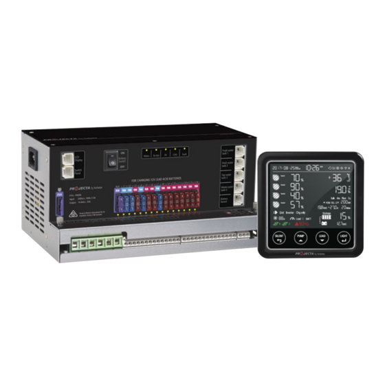
- Page 1 INTELLI-RV 12V POWER MANAGEMENT SYSTEM P/No. PM300-BT...
-
Page 2: Important Safety Information
IMPORTANT SAFETY INFORMATION Please read this manual thoroughly before use and store in a safe place for future reference. WARNINGS • Explosive gases. Prevent flames and sparks. Provide adequate ventilation during charging • Before charging, read the instructions • For indoor use. Do not expose to rain •... -
Page 3: Table Of Contents
CONTENTS 1. INTRODUCTION 1.1 Features 1.2 Monitor 1.3 Water tank probe 2. KEY FEATURES AND FUNCTIONS 2.1 Multiple inputs 2.2 Battery charger of stationery/service battery 2.3 Vehicle battery charger 2.4 Power supply mode 2.5 MPPT solar charger controller 2.6 Voltage charging relay (VCR) 2.7 Categorised outputs 2.8 Battery low voltage protection 2.9 Manual battery switch... -
Page 4: Introduction
1. INTRODUCTION PM300-BT is designed for use in caravans or motor homes. The unit has integrated functions such as: battery charger, distribution blocks, MPPT solar charger controller, charging relay, Low Voltage Disconnect (LVD), water pump controller, water tank indicator and LCD Display. The PM300-BT is designed for an easy installation and a user-friendly interface. -
Page 5: Features
1.1 Features • Smart battery charger 12V 35A (30A for charging current) • Multi stage adaptive charging algorithm • Active Power Factor Correction (PFC) charging • Temperature compensation charging • Voltage compensation charging • Float Charge for starter battery • Solar charge controller (MPPT), 30A •... -
Page 6: Monitor
1.2 Monitor PMLCD-BT The monitor is a digital control center for complete on-board power. FEATURES: • T-Bus design (can be connected to multiple devices) • System monitoring • Configuration • Built-in Bluetooth for pairing to smart phone Figure 3 Overview of Monitor 1.3 Water Tank Probe For PM300-BT, a maximum of 4 probes can be monitored. -
Page 7: Vehicle Battery Charger
10 days 1 hr 5mins VOLTAGE 11.5V CURRENT ½ lcc STAGE SOFT START BULK ABSORPTION FLOAT RECYCLE SOFT START ABSORPTION Increases battery life by gently starting to charge the battery Ensures a full charge to the battery without 50% of bulk overcharging BULK FLOAT... -
Page 8: Categorised Outputs
2.7 Categorised Outputs The 14 outputs are categorised into groups and controls as per below: TYPE DESCRIPTION POSSIBLE LOAD SUITABLE Class A1 Relay controlled output with fuse, protected by Water pump main master switch relay Class B Fused outputs, protected by master switch relay Ventilation fan etc Class C Live load... -
Page 9: Structure And Installation
3. STRUCTURE AND INSTALLATION 3.1 PM300-BT Power Management System Figure 8 Front panel of PM335 LABEL DEFINITION DESCRIPTION AC Mains AC input port Switch panel Comm port Connect to switch panel (Switch panel is not available on PM300-BT) LCD Display Comm port Connect to Monitor Battery switch... -
Page 10: Monitor
Figure 9 Dimension of PM335 (Unit: mm) Installation: PM335 can be installed on a horizontal surface or vertically on a wall. Please see following instructions: Ensure clearance on both sides of PM335 unit upon installation. A recommended clearance of 5cm on each side. Figure 10 Installation of PM335 (Unit: mm) 3.2 Monitor Figure 11 Dimension of Monitor PMLCD-BT (Unit:mm) -
Page 11: Water Tank Probe
Figure 12 Installation of Monitor PMLCD-BT (Unit:mm) 3.3 Water Tank Probe 3.3.1 PMWS400 Water Tank Probe Installation Figure 13 Dimension of PMWS400 (Unit:mm) Figure 14 Installation of PMWS400 3.3.2 PMWS200 Water Tank Probe Installation Figure 15 Dimension of PMWS200 (Unit:mm) Figure 16 Installation of PMWS200... -
Page 12: Wiring
4. WIRING 4.1 Material CODE NAME MODEL/LENGTH QTY P/No. ON DRAWING Power Management System PM335 Monitor PMLCD-BT Monitor Fresh water tank 1 level sensor Not included and to be Fresh water tank 1 level sensor ordered PMLCDC Tap water tank level sensor separately Waste water tank level sensor Solar... -
Page 13: System Schematic
4.2 System Schematic PMWS200/ PMWS200/ PMWS400 PMWS400 PMWS200/ Outdoor Battery Temperature PMWS400 PMWS200/ Temperature Sensor Sensor and Terminal PMWS400 Voltage PMTS PMBS Fresh Water Fresh Water Tap Water Waste Water Tank 1 Tank 2 Tank Tank Level Sensor Level Sensor Level Sensor Level Sensor •... -
Page 14: Preparation
4.3 Preparation PM300-BT system is designed with concept of ‘Plug in and Play’ in mind. To complete the easy installation, a screw driver and DC cables are required. Follow Table 5 recommendation for minimum wirings. CURRENT MINIMUM CABLE SIZE When running cables, if they pass through panels or wall, ensure the 0–5A 1.0mm or 18 AWG... -
Page 15: Display
5. DISPLAY 5.1 PM300-BT Power Management System P/No. PM335 Figure 21 An overview of PM335 COLOUR STATUS DESCRIPTION Mains GREEN AC input OK AC disconnected Quick flashing (flash twice every second) AC input abnormal Str Bat GREEN Alternator charging the SERVICE battery Slow flashing (flash once every second) Starter battery is >13.4V and is being charged by the AC... -
Page 16: Pm300-Bt Master Power Unit
5.2 Monitor PMLCD-BT Time Date Setting/Volume/Bluetooth Water tank 1 Temperature Water tank 2 Output power Water tank 3 Charging state Water tank 4 Service battery:Type/Capacity Power Source Service battery: Voltage/Current/Time to go Solar charge Service battery SOC (State of Charge) Water pump Voltage of vehicle battery Alarm error code... -
Page 17: Switch Explanation
5.2.2 Switch Explanation SWITCH FUNCTION DESCRIPTION SILENT & Stop the fan ventilation in order to reduce the noise Press ‘Silent/Esc’ button until shows on the Refer to 2.11 screen, then press ‘Light/Enter’. PUMP & To switch on/off pump Pump on: Pump off: The detailed steps are shown as below Figure 23 LOAD &... -
Page 18: Operation
6. OPERATION If there is conflict between the configuration on PM300-BT and the monitor, the monitor will flash as a reminder. 6.1 Configuration on PM335 Configuration of the battery type and capacity can be done through the App, Monitor or PM335 master power unit. 6.1.1 Charging Current and Battery Type 1 2 3 4 Dip switch definitions:... -
Page 19: Select Switch Local/Remote
6.1.2 Select Battery Switch Local/Remote This function offers a possibility for user to use a remote battery switch to power on/off the service battery output Local DIP SWITCH DESCRIPTION Local The switch on PM335 unit works Remote The remote switch works and local one Remote is disabled Figure 27 Local/Remote Select Switch... -
Page 20: Monitor Configuration Menu
6.2.1 Monitor Configuration Menu Set clock Set year Battery menu Set month Pumps enable or disable Set date Cut off Bluetooth Set 12-hour or 24-hour Factory reset Set hour Check firmware version Set minute Enable to updating firmware Figure 29 Date and Time setting Figure 28 Main menu of setting Select AGM battery Select GEL battery... -
Page 21: Maintenance
6.3 MAINTENANCE 6.3.1 Battery Monitor Maintenance There is a built-in battery measurement in the PM300-BT system. To assure the accuracy, maintain the system with the following instructions: 1. Fully charge the battery from AC grid instead of PV every 2 weeks. 2. -
Page 22: Trouble Shooting
7. TROUBLE SHOOTING 7.1 L.E.D Display on PM335 COLOUR STATUS DESCRIPTION Mains Green Quick flashing AC input abnormal (flash twice every second) Str Bat Green Quick flashing The Starter Battery is 2~13.4V or >16.0V, while (flash twice every second) AC power is connected. Green Quick flashing Solar input voltage error –... -
Page 23: Specification
8. SPECIFICATION MODEL PM335 MODEL PM335 ELECTRICAL SPECIFICATIONS ELECTRICAL SPECIFICATIONS Grid Nominal input voltage 240±10%VAC Battery Disconnect voltage AGM/GEL/WET 10.5VDC 50/60Hz Disconnect (default) (LVD) Power factor 0.95 LFP (LiFePO 11.2 VDC (Default) Input current at full 2.5A load Delay off time 60 sec Battery Starter Battery... -
Page 24: Warranty Statement
WARRANTY STATEMENT Applicable only to product sold in Australia Brown & Watson International Pty Ltd of 1500 Ferntree Gully Road, Knoxfield, Vic.,telephone (03) 9730 6000, fax (03) 9730 6050, warrants that all products described in its current catalogue (save and except for all bulbs and lenses whether made of glass or some other substance) will under normal use and service be free of failures in material and workmanship for a period of one (1) year (unless this period has been extended as indicated elsewhere) from the date of the original purchase by the consumer as marked on the invoice.
Need help?
Do you have a question about the INTELLI-RV PM300-BT and is the answer not in the manual?
Questions and answers