Table of Contents
Advertisement
Quick Links
USER MANUAL
AUTO KERATO-REFRACTOMETER
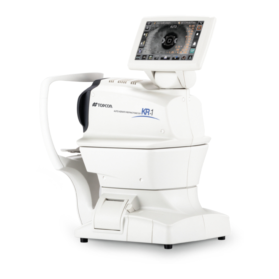
KR-1
0000100001000
0000100001000
0000100001000
0000100001000
ID
1
MANUAL
MANUAL
0
R
R
R
L
-1 . 25 25
-1.
S
S
-0 . 50 50
-0.
C
C
1 80
180
A
A
1
0
K
K
7 . 8 0
7 . 8 0
R1
R1
R1
R1
7 . 7 5
7 . 7 5
R2
R2
R2
R2
180
1 80
A
A
7.80
7.80
PR1
PR1
PR2
PR2
PR2
PR2
PR1
PR1
0 1 0 1
mm mm
PA1
PA1
PA1
PA1
12.00
12.00
VD
VD
R/K
M
HIGH
HIGH
FOG
FOG
Advertisement
Table of Contents

Related Manuals for Topcon KR-1


Summary of Contents for Topcon KR-1
- Page 1 -0 . 50 50 1 80 7 . 8 0 7 . 8 0 7 . 7 5 7 . 7 5 1 80 7.80 7.80 0 1 0 1 mm mm 12.00 12.00 HIGH HIGH USER MANUAL AUTO KERATO-REFRACTOMETER KR-1...
-
Page 3: Introduction
FEATURES This instrument features the following: • The KR-1 is simple to operate and measures the refraction and corneal curvature of the eye. • The position of the touch panel can be adjusted to accommodate the user's preferred position. • The auto start function facilitates quick measurements under the optimal condition. - Page 4 (4) Do not store the instrument where chemicals are stored or gas is generated. 2. NORMAL LIFE SPAN OF THE INSTRUMENT: 8 years from delivery providing regular maintenance is performed (according to the self-certifi- cation [Topcon data]) USER MAINTENANCE 1. Regularly measure the attached model eye and check the accuracy.
-
Page 5: How To Read This Manual
HOW TO READ THIS MANUAL • Read the instructions on pages 1 to 8 before using the machine. • Regarding connection to various devices, see "CONNECTING EXTERNAL I/O TERMI- NALS" on page 20. • If you would like an overview of the system, begin by reading "BASIC OPERATIONS"(page 24). -
Page 6: Displays For Safe Use
DISPLAYS FOR SAFE USE In order to encourage the safe use of the instrument and to avoid danger to the operator and oth- ers as well as damage to properties, warnings are described in the User Manual and marked on the instrument body. -
Page 7: General Safety Information
GENERAL SAFETY INFORMATION WARNINGS Ensuring the Safety of Patients and Operators When operating the instrument, do not touch the patient's eye or nose. Handling the cord on this product or cords associated with accessories sold with this product, will expose you to lead, a chemical known to the State of California to cause birth detects or other reproductive harm. - Page 8 CAUTIONS Ensuring the Safety of Patients and Operators To avoid injury when operating the chinrest up/down button, be careful not to catch the patient's fingers. Preventing Electric Shocks and Fires To avoid injury by electric shock, do not open the cover. For repair, call your service engineer. To avoid injury by electric shock when changing the fuse, turn off the power and pull off the power cable.
-
Page 9: Usage And Maintenance
For details, See “CLEANING THE INSTRUMENT” on page 65. DISCLAIMERS • TOPCON is not responsible for damage due to fire, earthquakes, actions or inactions of third persons or other accidents, or damage due to negligence and misuse by the user and any use under unusual conditions. -
Page 10: Positions Of Warning And Caution Indications
To secure safety, this equipment provides warnings. Correctly use the equipment following these warning instructions. If any of the following mark- ing labels are missing, please contact your dealer or TOPCON at the address stated on the back cover. Label... -
Page 11: Table Of Contents
CONTENTS INTRODUCTION ....................1 HOW TO READ THIS MANUAL ................3 SYMBOLS IN TEXT ..................3 DISPLAYS FOR SAFE USE ...................4 DISPLAYS ....................4 GENERAL SAFETY INFORMATION ..............5 USAGE AND MAINTENANCE ................7 USER MAINTENANCE...................7 FUSE CHANGE....................7 CLEANING OF MEASURING WINDOW............7 DISCLAIMERS .......................7 POSITIONS OF WARNING AND CAUTION INDICATIONS ........8 COMPONENTS COMPONENT NAMES..................11 COMPOSITION OF PARTS WHICH CONTACT THE HUMAN BODY ....11... - Page 12 OPTIONAL OPERATIONS DISPLAYING THE PATIENT ID (PATIENT No.) OR EXAMINER ID ....38 MEASURING ONE EYE ONLY ................38 MEASURING THE RIGHT EYE ONLY ............38 MEASURING THE LEFT EYE ONLY ............38 MEASUREMENT OF CORNEA DIAMETER ............39 MEASUREMENT ON THE ACTUAL IMAGE ..........39 MEASUREMENT ON THE STILL IMAGE ..........41 OUTPUT USING RS232C ..................43 INPUT USING USB ....................43...
-
Page 13: Components
COMPONENTS COMPONENT NAMES Main body Section Measuring head Eye height mark of Control panel measuring window Power unit Section Printer cover open switch Printer cover External I/O terminal cover Chinrest Section Power inlet Forehead rest Measuring window Eye height mark Chinrest tissue pin Chinrest Fuse folder... -
Page 14: Operation Method Of Control Panel
OPERATION METHOD OF CONTROL PANEL The control panel is a touch panel. Do not use any sharp tools; e.g. ball NOTE: point pen. To select any relevant item. Continue to press Used for continuous moving. (Moving of chinrest and measuring head) 00001000010000100001 00001000010000100001 0000100001... -
Page 15: Function Button
Reset button ......Returns the chinrest and measuring head to the initial position. Forward/backward button for measuring head ..... Moves the measuring head closer to/away from the patient's eye. Start button....... Starts measurement . Auto/Manual button....Selects Auto/Manual mode (A: Auto mode, M: Manual mode). -
Page 16: Monitor Screen
MONITOR SCREEN MEASUREMENT SCREEN Alignment mark Patient No. (Patient ID when patient ID is input) Outer alignment mark Operator ID Number of reading/setting Number of reading/setting (R, REF) (L, REF) Refractive power Refractive power measurement result (R) measurement result (L) Number of reading/setting Number of reading/setting (L, KRT) -
Page 17: Printer Output
PRINTER OUTPUT KRT typical value style and KRT print format are HV C(Cataract mode) mark Reliability factor Typical measured value of right eye corneal curvature Bar code Measured value of horizontal corneal curvature Work ID No. Measured value of vertical corneal curvature Operator ID Corneal astigmatic axis angle... - Page 18 KRT typical value style and KRT print format are R1R2 Barcode Work ID No. Operator ID Patient No. (Patient ID when patient ID is input) Device ID number Reliability factor Serial number C(Cataract mode) mark VD (vertex distance) Cylinder sign 3 readings of REF right measurement Result of refractory power (recordable up to 10 measurements)
-
Page 19: Printout Format Setting
ITEM INITIAL Classic Barcode Operator ID Name Date Date style Patient ID Device ID number Common Serial number Include error data TOPCON logo Message Message data NULL NULL NULL NULL Between the lines Auto Cut Print order DATA DATA DATA... -
Page 20: Standard Accessories
STANDARD ACCESSORIES The following are standard accessories. Make sure that all these items are included (quantity). Power cable (1) Chinrest tissue pin (2) Printer paper (2) Monitor cleaner (1) Chinrest tissue (1) Dust cover (1) Fuse (2) Accessory case (1) User manual, Unpacking and Assembing Rubber cap (1) (1 each) -
Page 21: Preparations
PREPARATIONS INSTALLATION When moving the instrument, two people should lift from the bottom of the device. One person lifting the device may cause harm to his back or CAUTION injury by falling parts. Also, holding areas other than the bottom and holding the External I/O terminal cover may cause injury, as well as damage to the instrument. -
Page 22: Connecting External I/O Terminals
Tilt the body slowly so that the POWER switch is on top and the power inlet at the bottom can be seen. Connect the power cable to the Power inlet. Insert the power cable plug into the 3-pin AC grounding receptacle. -
Page 23: Data Input
Connect the connection cable to the input terminal of the instrument. Connect the other end of the connection cable to the external device. For questions about connections, contact your TOPCON dealer. PRINTER PAPER SETTING To avoid failure or potential injury, do not open the printer cover CAUTION while the printer is in operation. - Page 24 Open the printer cover to the limit. Insert the printer paper in the direction shown below and pull out the paper end to your side by 7 to 8cm. Roll direction Bring the paper into the center, then close the printer cover. In case the printer cover is not firmly closed, printing will not start, and "CLOSE PRT COVER"...
-
Page 25: Recovery From Power Save Status
RECOVERY FROM POWER SAVE STATUS This instrument adopts the power save system for saving electric power. When the machine is not operated for a set time, the control panel becomes a screensaver. Tap the control panel. In a few seconds, the measurement screen is displayed and measurement is enabled. The time to start the power save status can be changed in the initial setting "Auto power save"... -
Page 26: Basic Operations
BASIC OPERATIONS PREPARATION BEFORE MEASUREMENT TURNING ON THE INSTRUMENT Make sure the power cable is connected properly. For the details of connection, refer to “CONNECTING POWER CABLE” on page 19. Press on the SWITCH. POWER Make sure that the title screen is displayed and then the MEASUREMENT screen is dis- played in a few seconds. -
Page 27: Patient Positioning
PATIENT POSITIONING To avoid electric shock, do not touch the external connection CAUTION terminal and the patient at the same time. To avoid injury when moving the chinrest up/down button, be CAUTION careful not to catch the patient's fingers. To avoid injury when operating the machine, be careful about the cover not to catch fingers of the patient. - Page 28 Place the patient's chin on the chinrest and check that his/her forehead is touching to the forehead rest. Press the button to adjust the chinrest height until the eye height mark of the UP/DOWN chinrest reaches the same height as the patient's eye. At this moment, confirm that the height mark of the measuring window is at the height of the patient's visual line.
-
Page 29: Auto Mode Measurement
AUTO MODE MEASUREMENT Auto measurement mode may not be possible, in case the eyelid and the eyelashes cover the pupil. NOTE: If this occurs, the operator should tell the patient to open their eyes as wide as possible, or lift the eyelid to allow for measurement. Auto measurement mode may not be possible due to frequent blinks or existing abnormalities in the corneal surface caused corneal dis- NOTE:... -
Page 30: Alignment And Measurement
ALIGNMENT AND MEASUREMENT Alignment can be operated from the control panel. When the pupil is displayed, tap the display around the pupil. The measuring head moves to display the pupil image and alignment dot on the center of the screen. Then tell the patient to look at red-roof house. -
Page 31: Displaying Measurement Values
Alignment starts automatically, and measurement is performed. The measurement result is displayed. 0000100001000 0000100001000 0000100001000 0000100001000 3/3 3/3 AUTO AUTO 0/3 0/3 - 1. -1 . 25 25 - 0. -0 . 50 50 1 8 0 18 0 3/3 3/3 0/3 0/3 7. -
Page 32: Manual Mode Measurement
MANUAL MODE MEASUREMENT SETTING THE MANUAL MODE Check the MEASUREMENT screen is on. If the button is "M," the mode is AUTO/MANUAL Manual mode. If "A" (Auto mode) is displayed, tap it and change to "M". 0000100001000 0000100001000 0000100001000 0000100001000 0/3 0/3 MANUAL MANUAL... - Page 33 If the pupil is not displayed on the control panel, move the measuring head by press the control panel, checking the eye height mark on the measurement win- dow as a guide (see page 26). When the measuring head has reached the limit of movement (vertical/lateral directions), a yellow-colored limit mark appears, showing it is the movement limit in that direction.
- Page 34 When the main body is brought closer to the patient's eye, alignment arrows appear on the control panel screen. 0000100001000 0000100001000 0000100001000 0000100001000 0/3 0/3 MANUAL MANUAL 0/3 0/3 0/3 0/3 0/3 0/3 Outer alignment mark FORWARD FORWARD Alignment arrows mm mm 13.75 13.75...
-
Page 35: Displaying Measurement Values
When the alignment dot becomes smaller in size and "Alignment OK" is displayed, tap the button. START Even if fine alignment has not been achieved, measurement can be performed by tapping the button. To ensure correct measurement, try to get fine align- START ment. -
Page 36: Print-Out Of Measurement Values
PRINT-OUT OF MEASUREMENT VALUES • To avoid a paper jam in the printer, do not feed the paper if it is partly cut or wrinkled. • To avoid discoloring of the printer paper (particularly the recording area) during storage, use a polypropylene bag and not one con- taining plasticizer (PVC, etc.). -
Page 37: Clearing Measurement Values
CLEARING MEASUREMENT VALUES Tap the button on the control panel. ALL CLEAR All measurement values of both eyes are cleared. 0000100001000 0000100001000 0000100001000 0000100001000 3/3 3/3 AUTO AUTO 3/3 3/3 -1.25 25 -0.25 25 -0.50 50 -0.50 50 3/3 3/3 3/3 3/3 7.80 7.80... -
Page 38: Displaying All Measurement Data
DISPLAYING ALL MEASUREMENT DATA Normally the latest measurement is displayed, but it is possible to display and confirm all mea- surement data. Tap the button of the control panel. TARGET IMAGE 0000100001000 0000100001000 0000100001000 0000100001000 3/3 3/3 AUTO AUTO 3/3 3/3 - 1 . -
Page 39: Operation Of After Use
When no data is memorized, the data table shows blank. To change "REF data" and "KRT data," tap the REF/KRT button. RIGHT LEFT 7.80 7.75 7.80 7.75 7.80 7.75 7.80 7.75 * 7.80 7.75 7.80 7.75 * 7.80 7.75 7.80 7.75 When the reliability of KRT data is low, "*"... -
Page 40: Optional Operations
OPTIONAL OPERATIONS DISPLAYING THE PATIENT ID (PATIENT No.) OR OPERATOR ID A patient ID or operator ID of up to 13 characters can be input and displayed on the control panel and printout. However, if no patient ID is input, the patient No. is allocated automatically by the device. button. -
Page 41: Measurement Of Cornea Diameter
MEASUREMENT OF CORNEA DIAMETER MEASUREMENT ON THE ACTUAL IMAGE Tap the button/ button to select the right/left eye. 0000100001000 0000100001000 0000100001000 0000100001000 0/3 0/3 MANUAL MANUAL 0/3 0/3 0/3 0/3 0/3 0/3 13.75 13.75 0 1 0 1 mm mm Tap the button. - Page 42 When the pupil is displayed, tap around the pupil. The measuring head moves to display the pupil image and alignment dot at the center of the screen. R: 0. 00 R :0 .00 L:0.00 L:0 .0 0 R : 0 . 0 0 R :0 .0 0 L:0.00 L:0 .0 0...
-
Page 43: Measurement On The Still Image
Tap the button and move to the other eye. In like manner, measure the other eye. Tap the button and measure the other eye. EXIT MEASUREMENT ON THE STILL IMAGE When KRT measurement values are available, the still image of the measurement is dis- played. - Page 44 Tap either of the (R)/(L) buttons and move the positioning POSITIONING BAR CONTROL bar. R : 0 . 0 0 R : 0 .0 0 L : 0 .00 L : 0 .0 0 Follow steps 6 to 8 of "MEASUREMENT ON THE ACTUAL IMAGE." The cornea diameter is displayed.
-
Page 45: Output Using Rs232C
OUTPUT USING RS232C This instrument can output data to a PC, etc via the RS232C interface. Connect the interface cable to RS232C OUT. Refer to “CONNECTING EXTERNAL I/O TERMINALS” on page 20. Set up of data communication settings. For details, refer to “DATA COMMUNICATION (COMM)” on page 52. Perform measurements. -
Page 46: Operating The Setup Screen
SETTING FUNCTIONS ON SETUP SCREEN OPERATING THE SETUP SCREEN Various functions can be set on the SETUP screen. PREPARATONS FOR SETTING Make sure that the power cable is connected. For connection, refer to “CONNECTING POWER CABLE” on page 19. Turn ON the switch. -
Page 47: Outline Of Setup Screen Operations
OUTLINE OF SETUP SCREEN OPERATIONS and select the subject of setting. INDEX Initial Buzzer Print Start mode Comm Auto Print Printer Operator ID Patient No. reset Special Show patient ID Required patient ID Device ID number Return Operate the button or button, as necessary, and display the NEXT PAGE BACK PAGE... - Page 48 UP/DOWN BUTTON: Tap up/down buttons on the screen and change setting. Up/Down buttons TEN-KEY: Tap ten-key on the screen and enter the figure. If there are several windows to enter, tap the window to enter the figure by ten-key. Tap and fix the input value.
-
Page 49: Returning To The Measurement Screen
RETURNING TO THE MEASUREMENT SCREEN Tap the button. RETURN Operator ID Patient No. reset Special Show patient ID Required patient ID Device ID number Return The Measurement screen is displayed. 00001000010000100001 00001000010000100001 0000100001 0000100001 AUTO AUTO 3/3 3/3 3/3 3/3 - 1 . -
Page 50: List Of Setup Items
LIST OF SETUP ITEMS Setup items are categorized into 6 large indexes. "Initial" .....items related to the initial status after power on "Print" ......items related to output from the internal printer "Comm" ....items related to data output with the external device "LAN".......items related to output using the LAN "Operator ID"... - Page 51 Descriptions Options Details Initial value 1° Axial angle is displayed by 1° step. Axis step 1° 5° Axial angle is displayed by 5° step. 0.00 VD value is set to 0mm (contact lens). 12.00 VD value is set to 12.00mm (eyeglass lens). 13.75 13.75 VD value is set to 13.75mm (eyeglass lens).
-
Page 52: Setting Of Internal Printer (Print)
Serial number Serial No. is printed. "Error" data is not printed. ERROR data "Error" data is printed. TOPCON TOPCON logo is not printed. logo TOPCON logo is printed. Message is not printed. Message Message is printed. Message Set by key- String of up to 72 characters. - Page 53 Description Options Details Initial value Measurement values are printed in terms of DATA REF or KRT. Print order Both REF measurement value and DATA KRT measurement value are printed in order of right eye and left eye. VD value (Vertex distance) is not printed. VD value (Vertex distance) is printed.
-
Page 54: Data Communication (Comm)
Description Options Details Initial value Only REF data are output. Output Data Only KRT data are output. All measurement value is output. OLD TOPCON format NEW TOPCON format Format STD1 TOPCON STD1 format STD2 TOPCON STD2 format STD4 TOPCON STD4 format RS-232C port is disabled. -
Page 55: Lan Connection (Lan)
XML file output XML file is output. REF/KRT data file is not output. REF/KRT STD2 REF/KRT data are output in TOPCON STD2 format data format STD4 REF/KRT data are output in TOPCON STD4 format Shared folder (up to 32 characters) -
Page 56: Troubleshooting
TROUBLESHOOTING MESSAGE LIST "OVER-SPH" Spherical power exceeds +22D or -25D. "OVER-CYL" Cylindrical power exceeds ±10D. "OVER-R" Corneal curvature exceeds 5.00-10.00mm. "NO TARGET" There is no target or the eye image is too dark. "AGAIN" There is more than ±5D difference from the previous measure- ment value. -
Page 57: Trouble-Shooting Operations
If a problem is suspected, use the following check list. If following instructions does not improve the condition, or if your problem is not included in the list, contact your dealer or TOPCON at the address on the back cover. CHECK LIST... -
Page 58: Specifications And Performance
SPECIFICATIONS AND PERFORMANCE SPECIFICATIONS AND PERFORMANCE Range of Refractometry Measurement Spherical refractive power: -25 to +22D (0.12D/0.25D steps) Cylindrical refractive power: 0D to 10D (0.12D/0.25D steps) Direction of astigmatic axis: 0° to 180° (1°/5° steps) (where, spherical refractive power + cylindrical refractive power +22D, or spherical refractive power + cylindrical refractive power -25D) Measured minimum pupil diameter: 2mm... -
Page 59: Environmental Conditions Of Use
ENVIRONMENTAL CONDITIONS ENVIRONMENTAL CONDITIONS OF USE Temperature: +10°C to + 40°C Humidity: 30% to 90% RH(without condensation) Atmospheric pressure: 700hPa to 1060hPa ENVIRONMENTAL CONDITIONS OF STORAGE (Product unprotected, ready for operation, power supply not connected) *Temperature: +10 °C to + 40 °C Humidity: 10% to 95% (without condensation) Atmospheric pressure:... -
Page 60: Electromagnetic Compatibility
Guidance and manufacturer's declaration - electromagnetic emissions The KR-1 is intended for use in the electromagnetic environment specified below. The customer or the user of the KR-1 should assure that it is used in such an environment. Emissions test Compliance... - Page 61 Guidance and manufacturer's declaration - electromagnetic immunity The KR-1 is intended for use in the electromagnetic environment specified below. The customer or the user of the KR-1 should assure that it is used in such an environment. IEC 60601 Compliance...
- Page 62 Guidance and manufacturer's declaration - electromagnetic immunity The KR-1 is intended for use in the electromagnetic environment specified below. The customer or the user of the KR-1 should assure that it is used in such an environment. IEC 60601 Compliance...
- Page 63 Recommended separation distance between portable and mobile RF communications equipment and the KR-1 The KR-1 is intended for use in an electromagnetic environment in which radiated RF distur- bances are controlled. The customer or the user of the KR-1 can help prevent electromagnetic...
-
Page 64: Electric Rating
ELECTRIC RATING Source voltage:100-240V AC, 50-60Hz Power input: 75VA SAFETY DESIGNATIONS PER IEC 60601-1 STANDARD • Type of protection against electric shocks: Class I The Class I equipment provides means to connect itself to the protective grounding system of utilities to thereby independently provide protection against electric shocks by keeping con- nectable metal components nonconductive in case of a failure in the basic insulation. -
Page 65: Operation And Principle Of Operation
CCD camera. An internal computer analyzes the image and calculates the curvature radius, corneal astigmatic axis and the corneal refractive values. The KR-1 projects a luminous flux (near-infrared light) for refractive measurement to retina, the reflected image is received by a CCD camera, and the spherical refractive power, cylindri- cal refractive power and the axis of astigmatism are determined through computation. -
Page 66: Reference
REFERENCE OPTIONAL ACCESSORIES • Adjustable instrument table AIT-16 The table height can be adjusted to facilitate measurement. Specifications • Dimensions ....525(W)x490(D)mm • Table height....660~880mm • Table size ....490x500mm • Weight.......approx. 23kg • Power consumption ..150VA (100-120V, 220-240V) • RS232C on-line cable SHAPE OF PLUG Country Voltage/frequency... -
Page 67: Maintenance
0.12D and perform measurement. If the measurement result is widely different from the value shown on the model eye, call your dealer or TOPCON at the address on back cover. CLEANING THE INSTRUMENT To ensure correct measurement, do not touch a light source for NOTE: Peripheral KRT measurement. -
Page 68: Daily Maintenance
When using the dust cover, tap the Reset button and return the chinrest and mea- suring head to their initial positions. ORDERING CONSUMABLE ITEMS • When ordering consumable items, tell the product name, product code and quantity to your dealer or TOPCON at the address of back cover. Product name Product code Product name... -
Page 69: Brightness Adjustment Of Control Panel
BRIGHTNESS ADJUSTMENT OF CONTROL PANEL • The control panel is optimally adjusted when shipped. • For control panel brightness adjustment, see "INITIAL (INITIAL SETTING)," "Control panel brightness" (page 49). PRINTER PAPER JAM To avoid failure or potential injury, do not open the printer cover CAUTION while the printer is in operation. -
Page 70: Fuse Change
FUSE CHANGE To avoid electric shocks during fuse change, be sure to unplug the power cable before removing the fuse lid. WARNING Also, do not plug the power cable with the fuse lid removed. Always use the attached fuse (3A 250V). Using any other type WARNING may cause malfunction and fire. -
Page 71: Supplying The Chinrest Tissue
SUPPLYING THE CHINREST TISSUE • When the chinrest tissue has run out, pull off chinrest tissue pins and place new tissue. Chinrest tissue pins Chinrest tissue MAINTENANCE... -
Page 72: Maintenance
MAINTENANCE CLEANING THE COVER Do not clean plastic parts with solvents. Benzine, thinner, ether and NOTE: gasoline may cause discoloring and decomposition. If the cover, control panel, etc. get soiled, wipe the surface with dry cloth. If the cover is noticeably stained, wipe the surface with a damp cloth which is moistened in a tepid water solution of neutral detergent. - Page 73 IPA FONT LICENSE AGREEMENT V1.0 The Licensor provides the Licensed Program (as defined in Article 1 below) under the terms of this license agreement (“Agreement”). Any use, reproduction or distribution of the Licensed Program, or any exercise of rights under this Agreement by a Recipient (as defined in Article 1 below) constitutes the Recipient’s acceptance of this Agreement.
- Page 74 3. THIS LICENSED PROGRAM IS PROVIDED BY THE LICENSOR “AS IS” AND ANY EXPRESSED OR IMPLIED WARRANTY AS TO THE LICENSED PROGRAM OR ANY DERIVED PROGRAM, INCLUDING, BUT NOT LIMITED TO, WARRANTIES OF TITLE, NON-INFRINGEMENT, MERCHANTABILITY, OR FITNESS FOR A PARTICULAR PURPOSE, ARE DISCLAIMED. IN NO EVENT SHALL THE LICENSOR BE LIABLE FOR ANY DIRECT, INDIRECT, INCIDENTAL, SPECIAL, EXTENDED, EXEMPLARY, OR CONSEQUENTIAL DAMAGES (INCLUDING, BUT NOT LIMITED TO;...
- Page 75 When calling please have ready the following information about your unit: • Machine type: KR-1 • Manufacturing No. (Shown on the rating plate on the right side of the base.) • Period of Usage (Please give us the date of purchase).
- Page 76 BACK COVER AUTO KERATO-REFRACTOMETER KR-1 41844 95015 Printed in Japan 2012.09-100LW5...
Need help?
Do you have a question about the KR-1 and is the answer not in the manual?
Questions and answers