Table of Contents
Advertisement
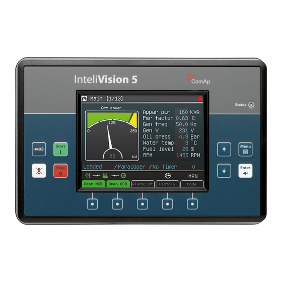
InteliVision 5
SW version 1.9.0
1 Document information
2 Installation and wiring
3 Graphical User Interface
5 Technical data
6 List of possible events
Copyright © 2017 ComAp a.s.
Written by ComAp
Prague, Czech Republic
ComAp a.s., U Uranie 1612/14a,
170 00 Prague 7, Czech Republic
Tel: +420 246 012 111
E-mail: info@comap-control.com, www.comap-control.com
5.7" Display Unit for
ComAp controllers
4
9
15
44
45
Global Guide
Advertisement
Table of Contents

Related Manuals for ComAp InteliVision 5


Summary of Contents for ComAp InteliVision 5
- Page 1 1 Document information 2 Installation and wiring 3 Graphical User Interface 5 Technical data 6 List of possible events Copyright © 2017 ComAp a.s. Written by ComAp Prague, Czech Republic ComAp a.s., U Uranie 1612/14a, 170 00 Prague 7, Czech Republic...
-
Page 2: Table Of Contents
2.2 How to Connect InteliVision 5 to controller 2.2.1 How to Connect InteliVision 5 to IG-NTx-BB 2.2.2 How to Connect InteliVision 5 to IS-NTx-BB 2.2.3 Terminating resistor 2.3 Direct communication between InteliVision 5 and IG/IS-NT-(BB) controllers 2.3.1 Option A 2.3.2 Option C 2.3.3 Option D 3 Graphical User Interface 3.1 Front panel... - Page 3 3.7.2 Support of TIER 4 Final standard 3.7.3 Change of all label colour 4 Quick Help 4.1 How to Connect InteliVision 5 to IGS-NT 4.2 How many InteliVision 5 can be used 4.3 Communication Error 4.4 How to View a Controller Status 4.5 How to View a Breaker Status...
-
Page 4: Document Information
1.2 About this guide InteliVision 5 is the 5,7” colour display unit for ComAp controllers. It is designed as a Plug and Play solution and it presents a simple solution with high visibility of all engine and gen-set data, monitoring information in colourful direction. - Page 5 Official version of the ComAp’s End User's Guide/Manual is the version published in English. ComAp reserves the right to update this End User's Guide/Manual at any time. ComAp does not assume any responsibility for its use outside of the scope of the Terms or the Conditions and the License Agreement.
-
Page 6: General Warnings
InteliGen NT BaseBox Complex Parallel Gen-set Controller InteliMains [[[Undefined Mains Supervision Controller Base Unit IM-NTC-BB variable Specific.BaseBox]]] Hybrid Gen-Set controller IS-NTC HYBRID InteliSys NTC Hybrid InteliDrive DCU Marine Engine controller for marine application ID-DCU MARINE InteliVision 5 - Global Guide... -
Page 7: Symbols In This Manual
1.7 Symbols in this manual Icons at the Top of InteliVision 5 Display Terminal is locked; no user is logged in Terminal is NOT locked; user is logged in Access lock is active; display is locked for security reasons Remote communication; when any remote connection to controller is active Icons at the Bottom of InteliVision 5 Display Mains icon;... - Page 8 Measurement screens Setpoints screen Alarm list screen History screen Help/Others screen InteliVision 5 - Global Guide...
-
Page 9: Installation And Wiring
6 back to Table of contents 2.1 Terminals and Dimensions InteliVision 5 Cutout 175 x 115 mm 2.2 How to Connect InteliVision 5 to controller InteliVision 5 is possible to connect to controller via NT-terminal port or via Direct connection. InteliVision 5 - Global Guide... -
Page 10: How To Connect Intelivision 5 To Ig-Ntx-Bb
2.2.1 How to Connect InteliVision 5 to IG-NTx-BB 2.2.2 How to Connect InteliVision 5 to IS-NTx-BB InteliVision 5 - Global Guide... -
Page 11: Terminating Resistor
Direct communication enables the usage of converters with constant communication speed in both directions between InteliVision 5 and the controller. From version 1.1.1 it is possible to run InteliVision 5 connected to controller RS232 or RS485 port with following setting in the controller:... - Page 12 RS232(2) mode = DIRECT RS485(2)conv. = DISABLED RS232(2) mode = DIRECT RS485(2)* RS485(2)conv. = ENABLED Note: * RS232 or RS485 (1) direct connection can be used. They cannot be used simultaneously. ** Only available in IG-NTC / IS-NT-BB InteliVision 5 - Global Guide...
-
Page 13: Option A
2.3.1 Option A 2.3.2 Option C Analogical to Option A for second RS232 port. InteliVision 5 - Global Guide... -
Page 14: Option D
2.3.3 Option D Note: Make sure that bias (pull up, pull down) resistors are connected only on one side of the RS485 line. 6 back to Installation and wiring InteliVision 5 - Global Guide... -
Page 15: Graphical User Interface
3 Graphical User Interface This chapter provides general information on how to operate the InteliVision 5 display unit. This manual is intended for everybody who is concerned with operation and controls of the gen-set. 3.1 Front panel 3.2 Metering Screens 3.3 Setpoints Screens... -
Page 16: Led And Buttons
3.1.1 LED and Buttons Status: Status LED indication (green = InteliVision 5 is powered) Navigation buttons: Arrows for movement + Menu and Enter button Context buttons: Control or select submenu/sub-options buttons Control buttons: Horn reset, Fault reset, Stop and Start buttons 3.1.2 Navigation Buttons... -
Page 17: Context Buttons
Acknowledges faults and alarms (active only in Alarm screen) Horn reset Deactivates the horn (audible alarm) Note: Start and Stop buttons work in MAN or SEM mode only. START and STOP buttons are independent on the InteliVision 5 screen, menu or sub-menu. InteliVision 5 - Global Guide... -
Page 18: Metering Screens
3.2 Metering Screens Various values can be seen on the metering screens. Metering screens appear after the InteliVision 5 and controller are powered up and initialization procedure is done. Automatic jump to the home metering screen is performed if there is 15 minutes of inactivity and there are no active and unconfirmed alarms in the controller. - Page 19 InteliVision 5 - Global Guide...
- Page 20 Other screens with ECU values, analogue or binary inputs/outputs can follow. It depends on the controller configuration. Note: Use ↑ or ↓ to scroll the screens. Screens could be hidden or the order of the screens could be modified by users. InteliVision 5 - Global Guide...
-
Page 21: Setpoints Screens
Setpoints could be presented as a numeric, text, string or mixed value and they can be changed in the following ways: 3.3.1 Numerical Value Change 3.3.2 String Selection 3.3.3 String Edit 3.3.4 Time and Date Edit 3.3.5 Combined Setpoints 3.3.6 Unauthorized access message InteliVision 5 - Global Guide... -
Page 22: Numerical Value Change
Use arrows ↑ or ↓ to go to a certain set-point (e.g. Load ctrl PtM) and press Enter button, see picture below: Use ↑ or ↓ buttons to select the string from the list and press the Enter button. InteliVision 5 - Global Guide... -
Page 23: String Edit
Use arrows ↑ or ↓ to go to a certain set-point (e.g. Time) and press Enter button, see picture below: Use ↑ ↓ buttons to select the number, → ← for the next position and press Enter button. InteliVision 5 - Global Guide... -
Page 24: Combined Setpoints
AlarmList screen, exclamation mark starts blinking on the measurement screens. A small alarm icon is placed also to heading to be visible in all screens of IV5 including newly generated screens from Screen editor or by adding new modules in configuration. See picture below: InteliVision 5 - Global Guide... - Page 25 RED colour Note: When a new alarm appears AlarmList screen is displayed automatically when Main Measurement screen is displayed. From different screen, AlarmList button has to be used to display AlarmList screen. InteliVision 5 - Global Guide...
-
Page 26: Where To Find Alarms
Unacknowledged alarm (not confirmed by Fault Reset button) Alarm without asterisk Acknowledged alarm (confirmed by Fault Reset button) Alarm written in colour background Active alarm Alarm written in black background Inactive alarm (resolved - visible only when unacknowledged) InteliVision 5 - Global Guide... -
Page 27: Ecu Alarmlist Page
Alarm activated with analogue value Alarm activated with binary inputs 3.4.3 ECU Alarmlist page InteliDrive controllers family controller have visually separated common and ECU alarms. The ECU Alarmlist page is accesible by the button in the user button section. InteliVision 5 - Global Guide... -
Page 28: History Screen
Scroll to the right side Note: History depends on a controller configuration. History is erased when controller configuration is changed and reprogrammed. For more information how to change history columns see GenConfig Reference Guide or GenConfig context help. InteliVision 5 - Global Guide... -
Page 29: Help/Others Menu
3. Use ↑ or ↓ to choose Language and use Enter. 4. Use ↑ or ↓ to choose correct language and press Enter Note: InteliVision 5 will reboot when the language is changed. This reboot does not affect control unit. 3.6.2 User/Password When a user is signed into the controller he can choose a user from the list of users (every user has got certain rights) and then password has to be used. -
Page 30: Communication
3.6.3 Communication To see information how to connect InteliVision 5 display to a controller, go to How to Connect InteliVision 5 to IGS-NT (page 35). 3.6.4 ControllerInfo To see information about the control unit see Controller info page. On the screen you can find information as... -
Page 31: Ecu Modules
Modules info is the screen where all connected modules can be seen, e.g. I-LB+, IGS-NT-E-COM etc. 3.6.7 InteliVision Info Information about the InteliVision 5 properties can be seen in IV info screen. See the picture below: InteliVision 5 - Global Guide... -
Page 32: Intelivision Settings
The Service screen is defined in Screen Editor tool or via xml description. Screen Editor is easy drag&drop way how to modify screens in InteliVision 5. Screen Editor is available as the part of GenConfig 2.6 and higher. -
Page 33: Other Features
3.7.1 User configurable soft keys buttons The user has possibility to assign various functions of configurable soft keys buttons - buttons on the bottom of Intelivision 5 (see figure below). Different functions can be assigned to any button of any screen. Pre-defined functions: Fast jump to any Measurement &... -
Page 34: Support Of Tier 4 Final Standard
3.7.2 Support of TIER 4 Final standard InteliVision 5 is ready to use in projects requiring the TIER4 Final standard. The figure below displays the illustrative set of supported symbols in all color variations. They are available to choose in Screen Editor (as Pictogram / GaugeBit / GaugeBitBlink instruments) during the IV5 screen modification. -
Page 35: Quick Help
InteliVision 5 menu, see Operator Interface chapter. 4.1 How to Connect InteliVision 5 to IGS-NT With version 1.1.1 or higher InteliVision 5 can be connected to the controller via RS-485 or RS-232 line. A user can choose between NT-Terminal connection and direct connection. -
Page 36: How Many Intelivision 5 Can Be Used
Note: For the information how to connect InteliVision 5 to the controller go to the Installation guide or Terminals and dimension chapter. RS 485 terminators have to be used to assure proper functionality.RS 485 port is galvanic separated and IV5 might be use for communication for long distance up to 1000m. -
Page 37: How To View A Controller Status
Note: Mode button and command buttons are disabled when active lock is active. SW button link has gray link around (when no colour background is used) and dark green or dark red when breaker status is highlighted. InteliVision 5 - Global Guide... -
Page 38: How To Control Circuits Breakers
5display. See picture bellow: 4.7 How to Change a Gen-set Mode To Change a Gen-set Mode: Press Mode context button (See the picture below). Use ↑ or ↓ to choose menu item and press Enter InteliVision 5 - Global Guide... -
Page 39: How To Log In
Use ↑ or ↓ to set the correct user and press Enter. See the picture below: Note: The controller is unlocked only when proper password is inserted. When user is log in. Green lock is displayed in the right upper corner and appropriate access level is indicated. See figure below: InteliVision 5 - Global Guide... -
Page 40: How To Enter A Password
"Controller is locked. Try entering correct password after X min" Message informs about time remaining for unlocking of the controller. The time in message is not actualized. For actual time a user should open login dialog again. InteliVision 5 - Global Guide... -
Page 41: How To Change A Password
Use ↑ or ↓ to choose Logout and press Enter. 4.12 How to Reprogram InteliVision 5 For programming of a new firmware, upgrade of fonts and logo download the InteliVision 5 has to be connected to any IG/IS-NT-(BB) controller to it’s NT-terminal interface, i.e. RS485(1)/display port. - Page 42 Note: It is possible to choose only firmware already imported to GC. Press Write to display button and wait until programming is complete Disconnect InteliVision 5 from the controller NT-terminal interface. It is not possible to program InteliVision 5 through the direct communication interface. InteliVision 5 - Global Guide...
-
Page 43: How To Change Display Brightness
The brightness of display can be changed by holding Menu button and repeated pressing or ¯. See the picture below: Two modes are available in InteliVision 5.To switch between Day or Night mode hold Menu button only. Pictogram for day or night appears on the screen. -
Page 44: Technical Data
1,1A at 8VDC 0,7A at 8 VDC Note: InteliVision 5 and the control unit should be used the same battery source. When external battery is needed because of long wiring and etc.. InteliVision 5 RD is recommended to use. Operating conditions Operating temperature -40 ˚C to +70 ˚C... -
Page 45: List Of Possible Events
Screen template missing Error Unsupported controller firmware, missing InteliVision 5 support. Screen template version Error Unsupported controller screen. InteliVision 5 firmware has to be updated. Corrupted display font. Font programming was not done properly. Display Font not valid Error firmware/font programming is necessary.
Need help?
Do you have a question about the InteliVision 5 and is the answer not in the manual?
Questions and answers
Hello, My generator is showing Sd/ECU. Whenever I want to start the generator the screen goes dark for 1-2 second then shows Sd/ECU and cannot start! any idea of what are the possible solutions?