Table of Contents
Advertisement
Advertisement
Table of Contents

Related Manuals for ACT Quantum Q4


Summary of Contents for ACT Quantum Q4
-
Page 1: Installation Manual
ADVANCED CHARGING TECHNOLOGIES Quantum Charger Installation Manual 710-00002.5... - Page 2 © 2019 Advanced Charging Technologies. All rights reserved Contact Information: Advanced Charging Technologies 16855 Knott Ave La Mirada, CA 90638 http://www.act-chargers.com/ Main 877-228-5922 Sales 877-228-5922 Service 877-228-5922 service@act-chargers.com 710-00002.5...
-
Page 3: Table Of Contents
Table of Contents Chapter 1: Quantum Charger Series ................... 4 .......................4 EATURES ...................4 EMOTE ONITORING APABILITIES Chapter 2: Safety Precautions ..................... 5 Chapter 3: Installation ......................8 ................8 HARGER NPACKING AND NSPECTION (NOT SUPPLIED) ..................8 EEDED OOLS ..................9 HARGER OUNTING PTIONS ........................ -
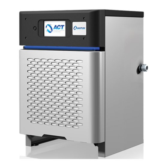
Page 4: Chapter 1: Quantum Charger Series
Chapter 1: Q UANTUM HARGER ERIES The Quantum Charger Series is part of ACT intelligent products and solutions. Featuring a modular and flexible design, reducing electrical infrastructure requirements to achieve greater energy savings. 1.1 Key Features § Modular design featuring: •... -
Page 5: Chapter 2: Safety Precautions
Chapter 2: S AFETY RECAUTIONS While every care has been taken to ensure the completeness and accuracy of this manual, Advanced Charging Technologies Inc. assumes no responsibility or liability for losses or damages resulting from the use of the information contained in this document. Due to technical improvements, some information contained in this manual may change without notice. - Page 6 DANGER: Risk of High Voltages – Lethal voltages are present within the charger enclosure whenever the AC mains supply is energized and/or the battery or load is connected. The bus bars and other internal components present the risk of electric shock WARNING: Risk of Explosive Gases –...
- Page 7 DANGER: Risk of Electric Shock and/or Electric Energy from High Current Levels – Do not touch un-insulated battery, connectors, bus bars or terminals. All tools used should be adequately insulated to avoid the possibility of shorting connections. Inspect cables often for damage to the insulation.
-
Page 8: Chapter 3: Installation
Option I: Using USB cable (recommended) § Type A Male USB cable § ACT Windows tablet or Windows laptop with ACT-Link software installed o Option II: Through Wi-Fi connection § ACT Mobile Router § ACT Windows tablet or Windows laptop with ACT-Link software installed 710-00002.5... -
Page 9: Charger Mounting Options
For wall mounting, only use mounting brackets especially designed for the Quantum Charger Series, available from your local ACT Dealer. The wall mount is also available with a pogo stick cable management system. Follow the installation instructions included in the Wall Mounting Kit for proper installation. -
Page 10: Post Stand
Post Stand The post stand provides a convenient floor-mount option. The charger mounts to the stand using the provided hardware in Post Stand Kit. It is also available with a pogo stick cable management system, providing easy connection to the battery and keeping cables off the floor when not connected. -
Page 11: Stacking
For floor mounting, chargers can be stacked to maximize area utilization. For Stacking, only use mounting brackets especially designed for the Quantum Charger Series, available from your local ACT Dealer. NOTE: When Stacking unit follow the Maximum number of stacked units... -
Page 12: Charger Electrical Installation
3.4 Charger Electrical Installation WARNING: DANGEROUS VOLTAGES AND CURRENTS ARE PRESENT IN THE AC MAINS WHEN ENERGIZED. ONLY TRAINED PERSONNEL SHOULD PERFORM THESE PROCEDURES, USING PROPER EQUIPMENT AND PROCEDURES. VERIFY THAT INPUT AND OUTPUT WIRING ADHERES TO ALL LOCAL SAFETY CODES AND STANDARDS. §... - Page 13 NOTE: For the Outdoor/GSE Charger remove the labyrinth that is behind the front and back cover to access the charger backplanes. The screws are located on the side. Outdoor/GSE Charger back Labyrinth 3. Inspect the DC fuse and battery cables, make sure the torque line is straight. If the torque line is not straight, TORQUE THE NUTS TO 55 INCH-POUND.
- Page 14 cable and cable strain relief need to have minimum rating of type 3R, and designated for outdoor use. NOTE: The Q4 charger has an alternative knockout at the bottom for AC connection 5. Connect the AC input power wires to the AC terminal block 6.
- Page 15 Outdoor/GSE Charger front Labyrinth The Power Module is not completely flushed on the chassis 9. With no battery connected to the charger, energize the source circuit and verify proper AC voltage at the line side of the charger switch. All line-to-line voltages should be within ± 10% of rated values and matched within 10 VAC.
- Page 16 12. Ensure that the LCD on the charger is calibrated by clicking the home button and verify you can navigate the menu. NOTE: Outdoor/GSE Chargers do not have a touch screen. NOTE: If the LCD is not responding to touch, please follow the procedure “...
-
Page 17: Chapter 4: Charger Settings
Follow the steps below to launch ACT-Link Software, program BATTview settings, and upload the settings to ACT-view.com cloud server. There are two options to program the charger settings, use a direct connection to the computer or tabled through USB cable, or using Wi-Fi connection 4.1 Option I: Using USB cable (recommended) - Page 18 Users can obtain ACTview User Name and Password by registering at www.act-view.com IMPORTANT: ACT-Link users need to log in once every 2 weeks with internet connection to keep their credential active. Please log in before you visit the customer site with internet connection.
- Page 19 6. Click on Charger Info. Enter the Client Charger ID, if any, this will help identify the charger on act-view without needing the full serial number. Also enter the Installation Date, Charger Type, and Time Zone, then click on Save and when the screen updates, you will see on the top right corner “Status Operation Done”...
- Page 20 8. Enter the Battery Capacity. When the charger is setup for multi-voltage operation, there will be a battery capacity associated with every Voltage. The other fields will have Default Values. Click on Save after all of the information is updated, then click on Back. NOTE: Charging Type (Conventional, Opportunity, or Fast) will be applied for all voltages.
- Page 21 12. Click on Update Firmware to ensure the latest firmware is installed on the charger (if any). Wait for the firmware to update and the charger to restart. 13. Close ACT-Link software and connect to a network with Internet access. NOTE: If there is no internet connection available at the 710-00002.5...
-
Page 22: Option Ii: Using Wi-Fi
14. Reopen ACT-Link software, click on the Upload button. This will insure that the settings are updated in ACT-View. This step could be done after leaving the customer site if there is no internet connection at the site. NOTE: ACT Mobile Router is not internet based. - Page 23 NOTE: ACT Mobile Router is a hand-held router that can be purchased from ACT. It comes preconfigured with ACT network credentials and can be used for configuring or downloading data from BATTviews and Quantum Chargers. ACT Mobile Router is not internet based. It will not connect to the cloud, it will just form a local area network.
-
Page 24: Chapter 5: Operation
Chapter 5: O PERATION Users operate the Quantum charger through the front LCD touch screen. The LCD screen is the main user interface for viewing and displaying operation and fault messages. It also allows limited charger programming options. 5.1 Powering the Charger Energize the AC mains (turn the main AC disconnect switch to the ON position if one exists). -
Page 25: Starting A Charge Cycle
(AC mains line- to-line) to ensure it is within ± 10%, and matches to 10 VAC or better. If the problem persists, contact the Dealer or ACT Service. 5.2 Starting a Charge Cycle 1. - Page 26 Waiting For BMS… If the charger doesn’t detect the BMS on the battery the following screen will be displayed after 45 seconds. If the following screen appears, it indicates an error on the communication board, restart the charger to clear the error. 710-00002.5...
- Page 27 NOTE: If the problem persists, contact the Dealer or ACT Service. If the charger is not set to start automatically, start the charge cycle by pushing the Green START button on the screen. NOTE: All Outdoor/GSE chargers have to be set for auto start since the touch screen is disabled.
- Page 28 Battery SOC Charger ID Time & Date Home button Battery Charge Charge Current indicator Wi-Fi Charging Connectivity timer Battery Charging Battery Charge Charging Voltage kWhr State Temperature 3. If the charger is set up for Li-Ion batteries the following screen will appear instead. 4.
- Page 29 6. Selecting EXIT stops the charger completely and defaults to the START screen. Selecting RESUME from the screen resumes the Charge Cycle and the screen will again display the charging operation display. 7. Once the Charge Cycle has completed, the charger will display “Completed” on the screen. 710-00002.5...
-
Page 30: Charger Led Color Indication
5.3 Charger LED Color Indication The LED strip attached under the charger front bezel, has a color indication to allow the user to identify the Charging Cycle and identify any issue with the charger. 710-00002.5... -
Page 31: Chapter 6: Maintenance
Chapter 6: M AINTENANCE regularly inspect air filter and clean or replace If the charger came with an air filter (located behind the front cover), as necessary. Location and environmental conditions must be taken into account when determining the frequency that the filter is cleaned or replaced. The air filter can be blown out or washed in warm soapy water (the filter must be completely dried prior to reinstall) Regularly inspect the DC cables for wear. -
Page 32: Chapter 7: Technical Specifications
Chapter 7: T ECHNICAL PECIFICATIONS 7.1 Nameplate Rating The Nameplate Rating Label is attached to the side of the charger; an example is shown below: The label specifies the Input Voltage and Current Rating for the charger, as well as the Output Rating. It also contains the UL Listing and File Number. -
Page 33: Appendix A: Floor Mounting Pattern
A: F PPENDIX LOOR OUNTING ATTERN Quantum Q4 Charger 710-00002.5... - Page 34 Quantum Q6 Charger 710-00002.5...
- Page 35 Quantum Q12 Charger 710-00002.5...
- Page 36 Outdoor/GSE Q6 Charger 710-00002.5...
- Page 37 REVISIONS NOTES: REV. DESCRIPTION DATE 1 - ADDITIONAL CLEARANCE REQUIRED AT SIDES FOR CABLES AND BEHIND UNIT FOR PROPER AIRFLOW. REFER TO INSTALLATION MANUAL FOR DETAILS. INITIAL DESIGN 01/14/19 UPDATED FOR CHASSIS LENGTH INCREASE 02/04/19 UPDATED FOR MINOR CHASSIS UPDATES 02/26/19 FOOTPRINT - LOOKING DOWN 0.484...
-
Page 38: Appendix B: Floor Stand Mounting Pattern
B: F PPENDIX LOOR TAND OUNTING ATTERN Quantum Charger Floor Stand Mounting Pattern Quantum GSE Charger Floor Stand Mounting Pattern 710-00002.5... -
Page 39: Appendix C: Wall Mounting Pattern
C: W PPENDIX OUNTING ATTERN Quantum Q4 Wall Mount 710-00002.5... - Page 40 Quantum Q6 & Q12 Wall Mount 710-00002.5...
Need help?
Do you have a question about the Quantum Q4 and is the answer not in the manual?
Questions and answers