Advertisement
User Manual
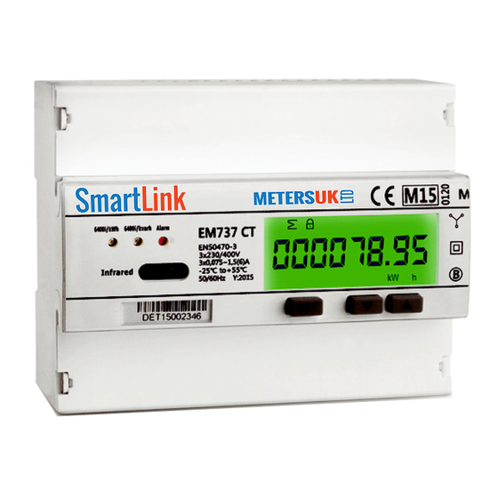
EM737 CT
Smart Energy Meter
KEY FEATURES
Three phase metering
•
Standard DIN rail Format (DIN43880)
• EN50470-3 Class B.
• Import & Export active energy
• Import & Export reactive energy
• Instant Volt, Amp, Power factor, Frequency, Active power,
Reactive power, Apparent power
• Isolate pulse output and IR (DIN43864)
• LCD display, 6 integer 2 decimal
• Large display LCD
• Internal transformer
• 27 CT rate can be selected
• Optional single-phase model
• RS232 M-Bus
• Program by button on the front panel
• Memory back-up (EEprom)
• 7 DIN modules
• MID approval
• The meter is intended to be installed in a Mechanical Environment 'M1', with Shock and Vibrations of low significance, as per
2004/22/EC Directive and should be installed in Electromagnetic Environment 'E2', as per 2004/22/EC Directive.
INDEX
1. Safety notice
2. Package Contents
3. EC Type Examination Certificate - upon request
4. Declaration of Conformity - upon request
5. Technical description
5.1 Performance criteria
5.2 Meter specification
5.3 Dimensions and sealing points
6. Wiring diagrams
7. Meter reading
8. Main function
8.1 Measuring Function
8.2 Display function
8.3 Electricity parameters measurement and monitoring
8.4 Communication Function
8.5 Alarm function
8.6 Pulse output function
9 Programming
9.1 Password verify
9.2 ID setting
9.3 Baud rate setting
9.4 CT rate setting
9.5 Password setting
10. Technical support
METERSUK
s a l e s @ m e t e r s . c o . u k 0 1 5 2 4 5 5 5 9 2 9
1. SAFETY NOTICE
The smart energy meter does not require special mechanical or electrical tools
for its installation. Mounting position (with any angle of tilt) has no effect on the
measurement functions of the meter.
Connection of the meter must follow the wiring diagram.
Incorrect connection of the meter to the electricity network will cause a major
display problem and can also cause serious damage to the meter.
Before connecting the meter, ensure the local conditions of the energy supply
is consistent with the information under the model number of the meter.
Preferably use shielded cables. Make sure that all connection cables are
not damaged during the installation of the meter and not energized or showing
any non-mechanical stress.
Repairs to the meter are to be made by a qualified electrician only.
PLEASE NOTE: The capacitors in the meter may still be charged after the meter
is disconnected for all power.
2. PACKAGE CONTENTS
Three phase, electronic energy meter
Instructions for assembly; ID setting; Baud rate setting;
CT rate setting; Password setting
Advertisement
Table of Contents

Summary of Contents for Meters EM737 CT
- Page 1 METERSUK User Manual s a l e s @ m e t e r s . c o . u k 0 1 5 2 4 5 5 5 9 2 9 EM737 CT Smart Energy Meter KEY FEATURES Three phase metering •...
-
Page 2: Technical Description
EM737 CT User Manual 5. TECHNICAL DESCRIPTION 5.1 PERFORMANCE CRITERIA Operating humidity ≤ 75% Storage humidity ≤ 95% Limit range of operating temperature -25°C - +55°C(3K6) Limit range for storage temperature -25°C - +55°C(1K4) Humidity 75% yearly average,95% on 30 days/year International standard EN50470-3 &IEC62053-21... - Page 3 (2 x 0.8 mm is also suitable). This type of cable should be used for the main wiring. For the wiring to the meters from the main wiring (last 1 .. 5m to the meter) a cable with smaller diameter may be used.
- Page 4 EM737 CT User Manual 6. METER WIRING Current Transformers IN LINE 1 LINE 2 LINE 3 NEUTRAL 8 + 11 = Active Test Pulse Output KwH 9 + 11 = Reactive Test Pulse Output KVA CT’s : Black = S2 | Red = S1...
-
Page 5: Meter Reading
EM737 CT User Manual 7. METER READING The viewing angle Operator meter should be at 45°. 8. MAIN FUNCTIONS 8.1 MEASURING FUNCTION On the EM737’S front panel, there are three LED lights, Active Energy pulse light, Reactive Energy pulse light and alarm Indicator. - Page 6 EM737 CT User Manual PULSE OUTPUT The test pulses are polarity dependant. Passive transistor output requires an external voltage source for correct operation. The external voltage source, must comply to the following:- Voltage (Ui) : 5-27V DC Maximum input current (Imax) : 27mA DC.
- Page 7 EM737 CT User Manual BAUD RATE SETTING Press “SET” button to bypass entering the Baud rate. Baud Rate = bits per second (Speed of communication). This is the rate that devices exchange information online (on a RS485 network) All devices MUST BE SET at the SAME rate otherwise they cannot communicate.
-
Page 8: 10. Technical Support
It is important to take a note of the new password as one cannot bypass the system. If the password is not crucial, leave the password as the default (0000) 10. TECHNICAL SUPPORT Any questions, please contact: Meters UK 01524 555 929 OTHER Branches must not be longer than 1200m. Longer branches could cause signal reflections and generate disturbances and consequent errors in the reception data.
Need help?
Do you have a question about the EM737 CT and is the answer not in the manual?
Questions and answers