Eaton Durant AMBASSADOR Series Installation And Operation Manual
Count control
Hide thumbs
Also See for Durant AMBASSADOR Series:
- Installation and operation manual (32 pages) ,
- Installation and operation manual (30 pages)
Advertisement
Durant
AMBASSADOR SERIES COUNT CONTROL
MODELS:
57600-402 (10-15 VDC)
57601-402 (115 VAC)
57601-452 (Red Display)
57602-402 (230 VAC)
57605-452 (24 VAC)
• Six Digit, Single Preset Main Counter
• Six Digit, Single Preset Batch Counter
• Eight Digit Totalizer
• 1/Tau Rate Meter
• Counter and Rate Meter Scaling
• Four User-Configurable Control Inputs
• One Output Relay
• Two Solid State Outputs
• RS-485 Serial Communications
• Red or Green Display
TABLE OF CONTENTS
1
3
4
5
12
13
15
18
24
Diagnostics and Troubleshooting
26
27
Durant
®
INSTALLATION AND OPERATION
MANUAL Number 57600-902-05
Durant
®
RST
RUN
HELP
CLR
PGM
EXIT
ENT
SEL
Advertisement
Table of Contents

Related Manuals for Eaton Durant AMBASSADOR Series


Summary of Contents for Eaton Durant AMBASSADOR Series
-
Page 1: Table Of Contents
Durant ® INSTALLATION AND OPERATION MANUAL Number 57600-902-05 AMBASSADOR SERIES COUNT CONTROL MODELS: 57600-402 (10-15 VDC) 57601-402 (115 VAC) 57601-452 (Red Display) 57602-402 (230 VAC) 57605-452 (24 VAC) • Six Digit, Single Preset Main Counter • Six Digit, Single Preset Batch Counter Durant ®... -
Page 2: Introduction
INTRODUCTION GENERAL DESCRIPTION MENU PROGRAMMING The Durant Ambassador 5760X-402 is a count control device Another unique feature of the Ambassador family of counters with three count registers - main counter, batch counter and is the menu driven programming. The two line alphanumeric totalizer. - Page 3 BLOCK DIAGRAM/OVERVIEW Pick Inp 1 Inp 2 RELAY 1 TOTALIZER OUTPUT Drop Inp 3 LOGIC Inp 4 Pick Count Main Signal Preset TRANSISTOR COUNT MAIN 1 OUTPUT SCALER Drop COUNTER LOGIC From Sensor(s) Pick Batch TRANSISTOR Preset RATE METER RATEMETER BATCH 2 OUTPUT Drop...
-
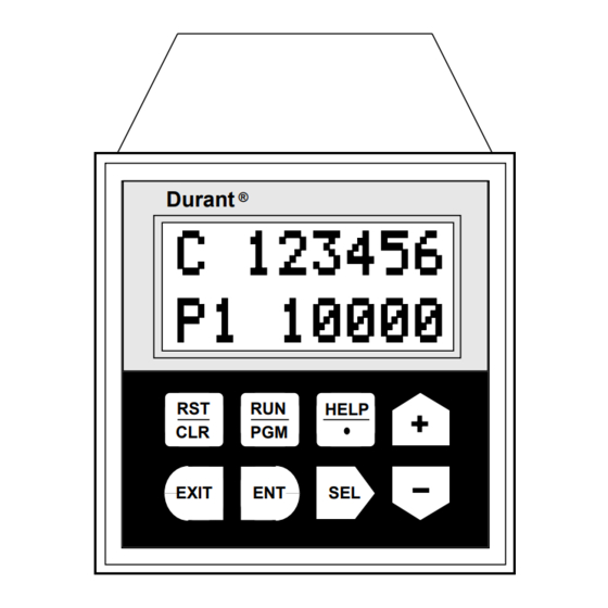
Page 4: Front Panel Features
FRONT PANEL FEATURES Durant ® Two line LCD Display - Shows count, preset, and rate values when unit is in the run mode. Displays programming information when the unit is in the program mode. HELP EXIT Key Functions Reset/Clear Key - In the run mode this key Exit Key - In the preset editing mode this key can be programmed to reset count values. -
Page 5: Run Mode Operation
RUN MODE OPERATION SELECTING DISPLAY INFORMATION CHANGING PRESET VALUES The Ambassador control has five available run mode dis- Preset 1 and the batch preset are set as follows: plays. Use the up and down arrow keys to select the desired display. - Page 6 PROGRAM MODE INTRODUCTION TO MENU PROGRAMMING ENTERING THE PROGRAM MODE The menu programming format used by the Ambassador series eliminates the need to memorize or look up program- To enter Then ming options. Program prompting is provided on the 2 line Press program alphanumeric display.
- Page 7 PROGRAMMING SCALERS AND COUNT INPUTS MAIN MENU SUB MENU EDIT MENU See pages 10-11 for detailed description of programming options. to exit to press EXIT main menu Data field flashes press press SEL selects digit to be programmed from left PROGRAM C SCALER C SCALER...
-
Page 8: Programming
PROGRAMMING CONTROL INPUTS See pages 10-11 for detailed description of MAIN MENU SUB MENU EDIT MENU programming options. to exit to press EXIT main menu press press Data field flashes Define input function from the PROGRAM INPUT 1 INPUT 1 EXIT list provided. - Page 9 PROGRAMMING OUTPUTS MAIN MENU SUB MENU VIEW MENU EDIT MENU to exit to to exit to press press EXIT EXIT Data field flashes main menu sub menu press press RELAY 1 RELAY 1 PROGRAM RELAY 1 RELAY 1 EXIT NORMAL NORMAL REVERSE OUT MODE...
- Page 10 PROGRAMMING SERIAL PORT AND OPTIONS See pages 10-11 for detailed description of MAIN MENU SUB MENU EDIT MENU programming options. to exit to press EXIT main menu Data field flashes press press PROGRAM SER PORT SER PORT Program two digit serial port address. SER PORT EXIT (Must be in a range from 00-99)
- Page 11 DESCRIPTION OF PROGRAM OPTIONS SCALERS RESET TO ZERO - the main counter resets to zero when a main counter reset occurs. The normal count direction is up C SCALER - the count scaler determines the value of each and the main counter outputs respond only when counting input pulse.
- Page 12 DESCRIPTION OF PROGRAM OPTIONS INPUT 1 LOCK PGM - all program editing is disabled (00-99 decimal). All communications to the control must (keyboard and serial) while input 1 is on (level sensitive). contain this number (in hexadecimal). Each unit must have a Preset values can still be changed serially or from the unique ID#.
-
Page 13: Scale Factors
CALCULATING SCALE FACTORS COUNT SCALING RATE SCALING The count scaler is a user programmable number which The 1/Tau rate meter calculates rate by measuring the time determines the count value of each input pulse. It is used to interval between input pulses, converting to frequency, and correct for a known amount of error (wheel wear, viscosity, multiplying by the rate scaler. -
Page 14: Rear Terminal Description
REAR TERMINAL DESCRIPTION Transistor 2 Output +12 Volt DC Transistor 1 Output DC Common Input 1 DC Common Input 2 Ground Input 3 No Connection Input 4 No Connection Count Input B No Connection Count Input A Relay 1 N.C. Communication + Relay 1 Com. -
Page 15: Wiring
REAR TERMINAL DESCRIPTION CONTINUED MODULAR COMMUNICATION JACK Switch 2: Input B sink/source Off: input B requires a current sinking input signal. The modular phone jack is an alternate connection to the RS- On: input B requires a current sourcing input signal. 485 communications port. - Page 16 AC WIRING/CONTACT INPUT WIRING AC Power Input (AC Models Only) Terminal 4 (Ground) and Terminals 2 and 3 (Com) are internally connected. Fuse Size Check part number on counter AC Power In U.S. label to verify correct voltage 115 V, 60 Hz 1/8 amp rating.
- Page 17 COUNT INPUT WIRING Current Sinking Sensor Current sinking (open collector NPN transistor) Count Input sensor output Do not connect Term 1 if sensor is Count Black Signal powered from another power supply. Wire colors shown correspond to Cutler-Hammer inductive proximity and photo sensors.
- Page 18 ENCODER WIRING/OUTPUT WIRING Shaft Encoder Wiring (Encoder Pin D) Blue Do not connect Term 1 if sensor is (Encoder Pin E) Yellow powered from another power supply. Wire colors shown are for Shaft Encoder quadrature encoder, do not connect Durant Pt # the yellow wire for a single channel encoder.
- Page 19 INTRODUCTION TO SERIAL COMMUNICATIONS The advanced communication capability of the Ambassador SERIAL COMMAND FORMAT control allows a host computer to read and reset counters, read and write presets, inhibit and enable counts, turn The general command format is shown below. Spaces are outputs on and off, lock and unlock the keyboard, and read used for clarity only and must not be transmitted.
- Page 20 SERIAL COMMAND/RESPONSE FORMAT 4. Numeric data required with the RCD command to specify responds by sending an ASCII “N” (not acknowledged) counter or preset to be read. Up to eight numeric charac- followed by a one character error code and a carriage return. ters are required for some commands.
- Page 21 SERIAL COMMANDS 0 Main counter Lock inputs are not affected by serial lock commands. If both 123.456 5A (cr) 1 Batch counter a lock input and a serial lock command are in effect, the user 123456 4B(cr) 2 Totalizer must remove both locks before programming from the key- AT 12345.678 66 (cr) 3 Rate board.
-
Page 22: Serial Communications
SERIAL COMMUNICATIONS SERIAL PROGRAM-MODE COMMANDS SAMPLE COMMUNICATIONS PROGRAM ESP — Enter Serial Programming The following BASIC program can be used to demonstrate the serial communications capability of the Ambassador This command causes the counter to enter the serial pro- controls. The program requires the user to enter an Ambas- gramming mode. - Page 23 SERIAL PROGRAMMING READ (RPI) WRITE (WPI) READ (RPI) WRITE (WPI) PROGRAM PROGRAM 00nnnnnn nnnnnn is a decimal number C SCALER INPUT 1 DISABLED between 000001 and 999999. If INPUTS SCALERS ..nnnnnn=000000, then 1.00000 is loaded. BYP P1 OUT CTRL C DEC PT where d is between 0 and 5.
- Page 24 SERIAL PROGRAMMING WRITE (WPI) READ (RPI) WRITE (WPI) READ (RPI) RST KEY DISABLED PROGRAM PROGRAM Enter 2 digit decimal ID #0-99. SER PORT OPTIONS RS C EDG SER PORT Program as 40nn where nn is between 00 and 99. The ID # RS C LVL will be converted to hexadecimal for transmission.
- Page 25 TROUBLESHOOTING SELF-TEST ROUTINES 3. If the same error occurs again there is a malfunction within the counter — return it to the factory for repair. The 5760X-402 counter has several built in self-test routines. The counter performs these tests each time power is applied. If the counter does not display an error, the unit is OK and If questionable operation ever occurs, run the self-test rou- can be put back in service.
- Page 26 TROUBLESHOOTING 4. Make and break a connection between terminals 4 IV. Other Problems: and 20 using a jumper wire. The main counter and totalizer should count up each time the connection Other problems are usually caused by programming and/or makes. If the counters do not count, send the unit to wiring errors.
-
Page 27: Specifications
SPECIFICATIONS POWER INPUT: COUNT INPUTS: AC Operation: 115 VAC (+/-15%) std., 50 to 60 Hz, 7 W Sink: Impedance: 4.6k ohms to +5 VDC 230 VAC (+/-15%) opt., 50 to 60 Hz, 7 W Voltage: high 3.5 to 34.0, low 0.0 to 24 VAC (+/- 15%) opt., 50 to 60 Hz, 7W 1.9 VDC DC Operation:... -
Page 28: Parts/Accessories
PARTS/ACCESSORIES Spare Parts 36172-202 Front Panel Gasket 48369-200 Mounting Clip 28748-200 Screw for Mounting Clip 48355-110 Terminal Strip - 10 Position 48355-112 Terminal Strip - 12 Position Ambassador Family Accessories 48183-401 Desk Mount Kit (enclosure for flat surface mounting) 58801-460 RS-485 to RS-232 Communications Converter 58801-461 RS-485 to RS-232 Communications Converter (Europe) - Page 29 Occupational Safety and Health Act of 1970, or any warranty is void if the product has been altered, misused, taken apart regulations issued thereunder. In no event shall Eaton be liable for or otherwise abused. ALL OTHER WARRANTIES, EXPRESS OR...
- Page 30 Durant Printed in U.S.A. 901 South 12th Street Watertown, WI 53094 920-261-4070 • 800-540-9242 • FAX 920-261-9097...
Need help?
Do you have a question about the Durant AMBASSADOR Series and is the answer not in the manual?
Questions and answers