Table of Contents
Advertisement
Quick Links
Advertisement
Table of Contents

Related Manuals for IBM RS/60000 Series


Summary of Contents for IBM RS/60000 Series
- Page 1 RS/6000 and Eserver pSeries Site and Hardware Planning Information SA38-0508-20...
- Page 3 RS/6000 and Eserver pSeries Site and Hardware Planning Information SA38-0508-20...
- Page 4 ©International Business Machines Corporation 1995, 2003. All rights reserved. Note to U.S. Government Users - Documentation related to restricted rights - Use, duplication, or disclosure is subject to the restrictions set forth in the GSA ADP Schedule Contract with IBM Corp.
-
Page 5: Table Of Contents
Contents About This Book ....... . xi ISO 9000 ........xi Highlighting . - Page 6 System Rack ....... . . 46 Enterprise Server Model S80 (7017) ......47 System Rack .
- Page 7 Unit Emergency Power Off ......141 Computer Room Emergency Power Off (EPO) ....142 Battery Holdup Times .
- Page 8 2103 Model H07 Fibre Channel Storage Hub ..... 233 2104 Model DL1 Expandable Storage Plus ..... . 234 2104 Model DU3 Expandable Storage Plus .
- Page 9 7203 Model 001 External Portable Disk Drive ..... . 281 7204 Model 010 1GB External Disk Drive ..... . . 282 7204 Models 112, 113, 114, 317, and 325 External Disk Drives .
- Page 10 HA Cluster Server AC Power Connections ..... . 374 Chapter 14. Specifications For non-IBM Rack Installation ....375 Rack Specifications .
- Page 11 Appendix. Notices ....... 385 Index ........387 Contents...
- Page 12 Site and Hardware Planning Information...
-
Page 13: About This Book
Online Publications RS/6000 and pSeries publications are available online. To access the online books, visit our Web site at: http://www.rs6000.ibm.com/resource/hardware_docs/ References to AIX Operating System This document may contain references to the AIX operating system. If you are using another operating system, consult the appropriate documentation for that operating system. - Page 14 v Diagnostics Information for Multiple Bus Systems, order number SA23-2769 contains common diagnostic procedures, error codes, service request numbers, and failing function codes to help diagnose and repair system problems. This manual is intended for trained service technicians. v High Availability Cluster Multi-Processing for AIX, Version 4.3: Enhanced Scalability Installation and Administration Guide, order number SC23-4284, is needed for HACMP/ES planning information.
-
Page 15: Trademarks
Trademarks The following terms are trademarks of the International Business Machines Corporation in the United States, other countries, or both: Eserver Enterprise Storage Server Magstar PowerPC POWER GTO POWERserver pSeries RS/6000 Seascape Versatile Storage Server Other company, product, and service names may be trademarks or service marks of others. xiii Preface... - Page 16 Site and Hardware Planning Information...
-
Page 17: Data Integrity And Verification
Data Integrity and Verification These computer systems contain mechanisms designed to reduce the possibility of undetected data corruption or loss. This risk, however, cannot be eliminated. Users who experience unplanned outages, system failures, power fluctuations or outages, or component failures must verify the accuracy of operations performed and data saved or transmitted by the system at or near the time of the outage or failure. - Page 18 Site and Hardware Planning Information...
-
Page 19: Chapter 1. Site Planning And Preparation Overview
Chapter 1. Site Planning and Preparation Overview Successful installation does not happen by accident: It takes planning. You are the most valuable resource in site planning because you know where and how your system, and devices attached to it, will be used. Site preparation for the complete system is the responsibility of the customer. -
Page 20: Planning Task Checklist
Planning Task Checklist This checklist provides a convenient way for you to document your planning progress. Working with your sales representative, establish completion dates for each of the tasks. You may want to review your planning schedule periodically with your marketing representative. Planning Step Person Responsible Target Date... -
Page 21: Csu/Ssr Feature Installation
CSU/SSR Feature Installation Attention: The following information indicates which features on various systems/models are intended to be installed by the customer and which features are to be installed by a System Service Representative (SSR) as part of a Miscellaneous Equipment Specification (MES). This information is for systems/models available as of the edition date. - Page 22 FC 6567 All Other Features Feature Code Feature Code Description 2842 POWER GXT4500P Graphics Accelerator 2856 IBM 7250 Attachment Adapter - PCI 2901 4.5GB F/W Ultra SCSI DASD Module 2908 9.1GB Ultra SCSI DASD Module 2909 18.2GB Ultra SCSI DASD Module 2911 9.1GB F/W Ultra SCSI DASD Module...
- Page 23 Feature Code Feature Code Description 6158 20 GB 4-mm Tape Drive, Bolt-in 6159 12 GB 4-mm Tape Drive, Bolt-in 6169 80/160 GB Internal Tape Drive with VXA Technology, Autodock 6185 20 GB 4-mm Tape Drive, Autodock 6294 Optional AC Power Supply for 7027 SCSI Drawers 6295 Optional bifurcated (Y-cable) Power Cord for 7027 SCSI Drawers 6309...
-
Page 24: General Considerations
General Considerations When determining the placement of your system, consider the following: v Adequate space for the devices. v Working environment of personnel who will be using the devices (their comfort, ability to access the devices, supplies, and reference materials). v Adequate space for maintaining and servicing the devices. -
Page 25: Footprint Example
Footprint Example The following table provides footprint dimensions for systems or devices for which they are appropriate. If you want to use full-sized footprints of the system units or devices, use the measurements provided to construct them out of folded newspaper or sheets of construction paper. You can then use them to plan a layout within the actual office space. - Page 26 Site and Hardware Planning Information...
-
Page 27: Chapter 2. Physical Characteristics Of Systems
Chapter 2. Physical Characteristics of Systems This chapter provides the physical characteristics for systems. This information can help you with physical planning for the products you have ordered. Note: The electrical and thermal information provided for systems does not include displays or a operators terminal (such as an ASCII terminal). -
Page 28: 7007 Powerportable N40
7007 POWERportable N40 Dimensions Height 51 mm 2.0 in. Width 290 mm 11.8 in. Depth 216 mm 8.5 in. Weight 3.13 kg 6.9 lbs Electrical Voltage range (V ac) 90 to 240 (autosensing) Frequency (hertz) 50 or 60 Power requirements 55 watts (typical) Temperature... -
Page 29: 7008 Powerstations M20 And M2A
7008 POWERstations M20 and M2A Dimensions Height 413 mm 16.1 in. Width 410 mm 16.0 in. Depth 459 mm 17.9 in. Weight Minimum 23.5 kg 52 lbs. Maximum 23.5 kg 52 lbs. Electrical Power source loading 0.22 (typical in kVA) Voltage range (V ac) 100 to 127 or 200 to 240 (autoranging) Frequency (hertz) -
Page 30: 7009 Compact Server C10 And C20
7009 Compact Server C10 and C20 Dimensions Height 394 mm 15.5 in. Width 191 mm 7.5 in. Width with pedestal 241 mm 9.5 in. Depth 432 mm 17.0 in. Weight Minimum 16 kg 35.0 lbs. Maximum 18 kg 39.5 lbs. Electrical Power source loading 0.232... -
Page 31: 7010 Xstation 130
7010 Xstation 130 Dimensions Height 72 mm 2.9 in. Width 375 mm 14.8 in. Depth 380 mm 15.0 in. Weight Minimum 7.7 kg 17 lbs. Maximum 9.5 kg 21 lbs. Electrical Power source loading 0.100 (maximum in kVA) Voltage range (V ac) 100 to 125 or 200 to 240 (autoranging) Frequency (hertz) 50 or 60... -
Page 32: 7010 Xstation 140 And 150
7010 Xstation 140 and 150 Dimensions Height 72 mm 2.9 in. Width 375 mm 14.8 in. Depth 380 mm 15.0 in. Weight Minimum 7.3 kg 16 lbs. Maximum 8.6 kg 19 lbs. Electrical Power source loading 0.100 (maximum in kVA) Voltage range (V ac) 100 to 125 or 200 to 240 (autoranging) Frequency (hertz) -
Page 33: 7010 Xstation Model 160
7010 Xstation Model 160 Dimensions Height 68 mm 2.75 in. Width 306 mm 12.00 in. Depth 306 mm 12.00 in. Weight Minimum 4.1 kg 10 lbs. Maximum 4.5 kg 9 lbs. Electrical Power source loading 0.121 (maximum in kVA) Voltage range (V ac) 100 to 125 or 200 to 240 (autoranging) Frequency (hertz) 50 or 60... -
Page 34: 220, And 230
® 7011 POWERstation and POWERserver 220, and 230 Dimensions Desktop Deskside Height 84 mm 3.3 in. 432 mm 17.0 in. Width¹ 406 mm 16.0 in. 216 mm 8.5 in. Depth 419 mm 16.5 in. 419 mm 16.5 in. Weight Minimum 9.0 kg 20 lbs. -
Page 35: 7011 Powerstation And Powerserver 250
7011 POWERstation and POWERserver 250 Dimensions Desktop Deskside Height 84 mm 3.3 in. 432 mm 17 in. Width¹ 406 mm 16 in. 216 mm 8.5 in. Depth 419 mm 16.5 in. 419 mm 16.5 in. Weight Minimum 9.0 kg 20 lbs. Maximum 11.5 kg 25 lbs. -
Page 36: 7012 Powerstation And Powerserver 34H, 355, 360, 365, 370, And 375
7012 POWERstation and POWERserver 34H, 355, 360, 365, 370, and Dimensions Desktop Deskside Height 162 mm 6.4 in. 466 mm 18.3 in. Width (at pedestal 456 mm 18.0 in. 241 mm 9.5 in. for deskside) Depth 523 mm 20.6 in. 523 mm 20.6 in. -
Page 37: 7012 Powerserver Models 380, 390, And 39H
7012 POWERserver Models 380, 390, and 39H Dimensions Desktop Deskside Height 162 mm 6.4 in. 452 mm 17.8 in. Width (at pedestal 442 mm 17.4 in. 241 mm 9.5 in. for deskside) Depth 478 mm 18.8 in. 478 mm 18.8 in. Weight Minimum 18.1 kg 40 lbs. -
Page 38: 7012 Model 397
7012 Model 397 Dimensions Desktop Deskside Height 162 mm 6.4 in. 452 mm 17.8 in. Width (at pedestal 442 mm 17.4 in. 241 mm 9.5 in. for deskside) Depth 478 mm 18.8 in. 478 mm 18.8 in. Weight Minimum 18.1 kg 40 lbs. 18.1 kg 40 lbs. -
Page 39: 7012 Models G30, G40, And G02
7012 Models G30, G40, and G02 Dimensions G30 & G40 Height 450 mm 17.75 in. 450 mm 17.75 in. Width 173 mm 6.9 in. 173 mm 6.9 in. Width (at pedestal) 280 mm 11 in. 280 mm 11 in. Depth 613 mm 24.1 in. -
Page 40: 7013 Powerstation And Powerserver 52H
7013 POWERstation and POWERserver 52H Dimensions Height 610 mm 24.0 in. Width 360 mm 14.2 in. Depth 675 mm 26.6 in. Weight Minimum 36.7 kg 81 lbs. Maximum 53.1 kg 117 lbs. Electrical Power source loading (typical in kVA) Voltage range (V ac) 100 to 125 or 200 to 240 (autoranging) Frequency (hertz) 50 or 60... -
Page 41: 7013 Powerstation And Powerserver 550L
7013 POWERstation and POWERserver 550L Dimensions Height 610 mm 24.0 in. Width 360 mm 14.2 in. Depth 675 mm 26.6 in. Weight Minimum 36.7 kg 81 lbs. Maximum 53.1 kg 117 lbs. Electrical Power source loading (typical in kVA) Voltage range (V ac) 100 to 125 or 200 to 240 (autoranging) Frequency (hertz) 50 or 60... -
Page 42: 7013 Powerstation And Powerserver 570 And 580
7013 POWERstation and POWERserver 570 and 580 Dimensions Height 610 mm 24.0 in. Width 360 mm 14.2 in. Depth 675 mm 26.6 in. Weight Minimum 36.7 kg 81 lbs. Maximum 53.1 kg 117 lbs. Electrical Power source loading 0.43 (typical in kVA) Voltage range (V ac) 100 to 125 or 200 to 240 (autoranging) Frequency (hertz) -
Page 43: 7013 Models 58H, 590, 59H, 591, And 595
7013 Models 58H, 590, 59H, 591, and 595 Dimensions Height 610 mm 24 in. Width 360 mm 14.2 in. Depth 675 mm 26.6 in. Weight Minimum 36.7 kg 81 lbs. Maximum 53.1 kg 117 lbs. Electrical Power source loading (typical in kVA) Voltage range (V ac) 100 to 125 or 200 to 240 (autoranging) Frequency (hertz) -
Page 44: 7013 Models J30, J40, And J01
7013 Models J30, J40, and J01 Dimensions J30 & J40 Height 610 mm 24 in. 610 mm 24 in. Width 360 mm 14.2 in. 360 mm 14.2 in. Depth 750 mm 29.5 in. 750 mm 29.5 in. Weight J30 & J40 Minimum 67 kg 148 lbs. -
Page 45: 7013 Model J50
7013 Model J50 Dimensions Height 610 mm 24 in. Width 360 mm 14.2 in. Depth 750 mm 29.5 in. Weight Minimum 67 kg 148 lbs. Maximum 84 kg 185 lbs. Electrical Power source loading (typical in kVA) Voltage range (V ac) 100 to 125 or 200 to 240 (autoranging) Frequency (hertz) 50 or 60... -
Page 46: 7014 Model S00 Rack
7014 Model S00 Rack Dimensions Height 1577 mm 62.0 in. Width 650 mm 25.5 in. Depth 1019 mm 40.1 in. Weight Base Rack 159 kg 349 lbs. Full Rack 594 kg 1309 lbs. Electrical² (sum specified values for drawers or enclosures in rack) DC Rack Power source loading maximum in kVA³... -
Page 47: S00 Rack Weight Distribution And Floor Loading
S00 Rack Weight Distribution and Floor Loading The S00 rack can be extremely heavy when several drawers are present. The following table shows the necessary weight distribution distances for the S00 rack when it is loaded. Rack System Width (2) Depth (2) Weight Distribution Distance (3) Weight (1) -
Page 48: S00 Rack Service Clearances
S00 Rack Service Clearances The lines of the footprint indicate the amount of space needed by the unit during service operation. For multiple racks placed side by side, the left and right clearances apply only to the leftmost and rightmost rack. -
Page 49: 7014 Rack
7014 Rack Model T00 Rack Dimensions Height 1804 mm 71.0 in. Capacity 36 EIA Units With PDP - DC only 1926 mm 75.8 in. Width without side 623 mm 24.5 in. panels With side panels 644 mm 25.4 in. Depth with rear door 1042 mm 41.0 in. -
Page 50: Model T42 Rack
Configuration dependent, base rack weight plus the weight of the drawers mounted in the rack. The rack can support up to a maximum weight of 35 lbs/EIA (Unit). 2. The total rack power should be derived from the sum of the power used by the drawers in the rack. 3. - Page 51 T00 and T42 Service Clearances and Caster Location The service clearances and caster locations are shown in the following illustration: 915 mm (36 in.) (4.8) (3.1) Rear cover thickness 20 mm (0.8 in.) Caster Location 2921 mm (115 in.) 915 mm 915 mm (36 in.) (36 in.)
- Page 52 Note: Rack units are large and heavy and are not easily moved. Because maintenance activities require access at both the front and back, extra room needs to be allowed. The footprint shows the radius of the swinging doors on the I/O rack. The illustration shows the minimum space required. T00 and T42 Racks Multiple Attachment Rack Rack...
- Page 53 T00 and T42 Rack Weight Distribution and Floor Loading The T00 and T42 racks can be extremely heavy when several drawers are present. The following table shows the necessary weight distribution distances for the T00 and T42 racks when it is loaded. Rack System Width (2)
-
Page 54: Service Clearances For S80 Or S85 System With T00 Style I/O Rack
Service Clearances for S80 or S85 System With T00 Style I/O Rack The amount of space needed by the units during service is indicated by large box of the footprint. For multiple racks placed side by side, the left and right clearances apply only to the leftmost and rightmost rack. -
Page 55: 7015 Powerserver 970B And 980B
7015 POWERserver 970B and 980B Dimensions Height 1578 mm 62.0 in. Width 650 mm 25.5 in. Depth 921 mm 36.0 in. Weight Minimum 205kg 450 lbs. Maximum 441kg 970 lbs. Electrical⁵ Maximum Entry Maximum Configuration Configuration Power source loading (max) Voltage range (V ac) 200 to 240 or -48V dc 200 to 240 or -48V dc... -
Page 56: 7015 Powerserver 990
7015 POWERserver 990 Dimensions Height 1578 mm 62.0 in. Width 650 mm 25.5 in. Depth 921 mm 36.0 in. Weight Minimum 205 kg 450 lbs. Maximum 441 kg 970 lbs. Electrical⁵ Maximum Entry Maximum Configuration Configuration Power source loading (max) Voltage range (V ac) 200 to 240 or -48V dc 200 to 240 or -48V dc... -
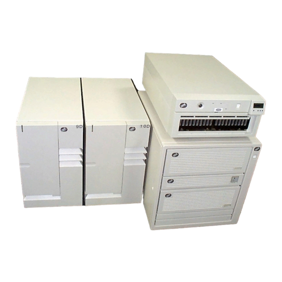
Page 57: 7015 Scsi Disk And Device Drawers
7015 SCSI Disk and Device Drawers Dimensions Height 171 mm 6.7 in. (4 EIA units) Width 443 mm 17.4 in. Depth 686 mm 27.0 in. Weight Minimum 25 kg 55 lbs. Maximum 48 kg 105 lbs. Electrical Power source loading 0.34 (typical in kVA) Voltage range (V ac) -
Page 58: 1/2-Inch 9-Track Tape Drive Drawer
1/2-Inch 9-Track Tape Drive Drawer Dimensions Height 222 mm 8.75 in. (6 EIA units) Width 483 mm 19.00 in. Depth 679 mm 26.75 in. Weight Minimum 48.2 kg 106 lbs. Maximum 48.2 kg 106 lbs. Electrical Power source loading (typical in kVA) Voltage range (V ac) 100 to 125 or 200 to 240 (selectable) Frequency (hertz) -
Page 59: 7015 System Rack R00
7015 System Rack R00 Dimensions Height 1578 mm 62.0 in. Width 650 mm 25.5 in. Depth with Std. Door 921 mm 36.0 in. Depth with SMP Door 1060 mm 41.8 in. Weight Base Rack 130 kg 286 lbs. Full rack 594 kg 1309 lbs. -
Page 60: R00 Rack Service Clearances
R00 Rack Service Clearances The broken lines on the footprint indicate the amount of space needed by the unit during normal operation. For multiple racks placed side by side, the left and right clearances apply only to the leftmost and rightmost rack. -
Page 61: 7015 Models R10, R20, And R21 Cpu Drawers
7015 Models R10, R20, and R21 CPU Drawers Dimensions Height 266.7 mm 10.5 in. Width 445.5 mm 17.5 in. Depth 610.0 mm 24.0 in. Weight Minimum 30.3 kg 65 lbs. (Configuration dependant) Electrical Power source loading 0.29KVA (typical in kVA) Voltage range (V ac) 200 to 240 Frequency (hertz) -
Page 62: 7015 Model R24
7015 Model R24 Dimensions Height 445.5 mm 17.5 in. Width 445.5 mm 17.5 in. Depth 710.0 mm 28.0 in. Weight Minimum 51.3 kg 112 lbs. (Configuration dependent) Electrical Power source loading 0.685 (typical in kVA) Voltage range (V ac) 200 to 240 or -48V dc Frequency (hertz) 50 or 60 Thermal output... -
Page 63: 7015 Model R30, R40, And R50
7015 Model R30, R40, and R50 Dimensions Height 267.0 mm 10.5 in. Width 445.5 mm 17.5 in. Depth 925.0 mm 36.4 in. Weight Minimum 59.7 kg 132 lbs. (Configuration dependent) Electrical Power source loading (typical in kVA) Voltage range (V ac) 200 to 240 or -48V dc Frequency (hertz) 50 or 60... -
Page 64: Enterprise Server Models S70 And S7A (7017, 7013, 7015)
Enterprise Server Models S70 and S7A (7017, 7013, 7015) System Rack Dimensions Height 1577 mm 62.0 in. Width 567 mm 22.3 in. Depth 1041 mm 40.9 in. Weight Minimum 400 kg 880 lbs. (Configuration dependant) Electrical Power source loading 1.887KVA (maximum in kVA) Voltage range (V ac) 200 to 240... -
Page 65: Enterprise Server Model S80 (7017)
Enterprise Server Model S80 (7017) The S80 can be used with a T00 or T42 style I/O rack. See “Model T00 Rack” on page 31. The rack can be ordered by feature code with your system. System Rack Dimensions Height 1577 mm 62.0 in. -
Page 66: S80 Rack Caster Location
S80 Rack Caster Location The following figure shows the caster locations for the S80 rack. For complete specifications on the S80 system rack, see “Enterprise Server Model S80 (7017)” on page 47. (4.4) Note (2.5) 1041 mm (40.9 in.) Note: Rear Swivel Caster Contacts Floor 21 mm (0.8 in.) -
Page 67: 7017 Model S85
7017 Model S85 The S85 can be used with a T00 or T42 style I/O rack. See “Model T00 Rack” on page 31. The rack can be ordered by feature code with your system. Dimensions Height 1577 mm 62.0 in. Width 565 mm 22.2 in. - Page 68 The following table lists maximum operating temperatures for system features at various altitudes. 305 m 610 m 914 m 1219 m 1524 m 1829 m 2134 m 2438 m 2743 m 3048 m (1000 ft) (2000 ft) (3000 ft) (4000 ft) (5000 ft) (6000 ft) (7000 ft)
-
Page 69: S85 Rack Caster Location
S85 Rack Caster Location The following figure shows the caster locations for the S85 rack. For complete specifications on the S85 system rack, see “7017 Model S85” on page 49. (4.4) Note (2.5) 1041 mm (40.9 in.) Note: Rear Swivel Caster Contacts Floor 21 mm (0.8 in.) Radius From... -
Page 70: S70 Scsi I/O Drawer 7 Eia
S70 SCSI I/O Drawer 7 EIA Dimensions Height 306.2 mm 12.1 in. Width 442.4 mm 17.4 in. Depth 748.2 mm 29.5 in. Weight Minimum configuration 43 kg 95 lbs. Maximum configuration 61 kg 135 lbs. Electrical Power source loading (typical in kVA) Power source loading (maximum in kVA) Voltage range... -
Page 71: S7A, S80, And S85 Scsi I/O Drawer 10 Eia
S7A, S80, and S85 SCSI I/O Drawer 10 EIA Dimensions Height 440.0 mm 17.3 in. Width 443.2 mm 17.5 in. Depth 843.2 mm 33.2 in. Weight Minimum configuration 89 kg 195 lbs. Maximum configuration 93 kg 205 lbs. Electrical Power source loading (typical in kVA) Power source loading (maximum in kVA) -
Page 72: S70, S7A And S80 I/O Rack
S70, S7A and S80 I/O Rack Dimensions Height 1577 mm 62.0 in. Width 650 mm 25.5 in. Depth 1019 mm 40.1 in. Weight (Base Rack) 159 kg 349 lbs. Electrical (see specifications for drawers or enclosures) Temperature (see specifications for drawers or enclosures) Requirements Humidity (see specifications for drawers or enclosures) - Page 73 Rack Configuration (AC Systems) Note: Rack units are large and heavy, and they are not easily moved. Because maintenance activities require access at both the front and back, extra room must be allowed. The footprint shows the radius of the swinging doors on the I/O rack. The illustration shows the minimum space required. Chapter 2.
- Page 74 Rack Configuration (-48v DC Systems) Note: Rack units are large and heavy, and they are not easily moved. Because maintenance activities require access at both the front and back, extra room must be allowed. The footprint shows the radius of the swinging doors on the I/O rack. The illustration shows the minimum space required. Site and Hardware Planning Information...
-
Page 75: 7020 Entry Workstation Model 40P
7020 Entry Workstation Model 40P Dimensions Desktop Deskside Height 124 mm 4.9 in. 477 mm 18.8 in. Width¹ 454 mm 17.9 in. 215 mm 8.5 in. Depth 447 mm 17.6 in. 447 mm 17.6 in. Weight Minimum configuration 12 kg 26 lbs. Maximum configuration 14.5 kg 32 lbs. -
Page 76: 7024 Entry Deskside Powerpc Server E Series
7024 Entry Deskside PowerPC Server E Series Dimensions Height 648 mm 25.5 in. Width¹ 315 mm 12.4 in. Depth 450 mm 17.7 in. Weight Maximum 25 kg 55 lbs. Electrical Power source loading 0.17 (typical in kVA) Voltage range (V ac) 100 to 127 or 200 to 240 (switchable) Frequency (hertz) 50 or 60... -
Page 77: 7025 Deskside 6F0 Series
7025 Deskside 6F0 Series Dimensions Height 610 mm 24.0 in. Width 483 mm 19.0 in. Depth 728 mm 28.7 in. Weight Minimum configuration 70 kg 155 lbs. Maximum configuration 95 kg 209 lbs. Electrical Power source loading typical in kVA 0.42 Power source loading maximum in kVA 0.63... - Page 78 The following table lists maximum operating temperatures for FC 6134 at various altitudes. 305 m 610 m 914 m 1219 m 1524 m 1829 m 2134 m 2438 m 2743 m 3048 m (1000 ft) (2000 ft) (3000 ft) (4000 ft) (5000 ft) (6000 ft) (7000 ft)
-
Page 79: 7025 Deskside 6F1 Series
7025 Deskside 6F1 Series Dimensions Height 610 mm 24.0 in. Width 483 mm 19.0 in. Depth 728 mm 28.7 in. Weight Minimum configuration 70 kg 155 lbs. Maximum configuration 95 kg 209 lbs. Electrical Power source loading typical in kVA 0.59 Power source loading maximum in kVA 0.86... - Page 80 The following table lists maximum operating temperatures for FC 6134 at various altitudes. 305 m 610 m 914 m 1219 m 1524 m 1829 m 2134 m 2438 m 2743 m 3048 m (1000 ft) (2000 ft) (3000 ft) (4000 ft) (5000 ft) (6000 ft) (7000 ft)
-
Page 81: 7025 Deskside F30 Series
7025 Deskside F30 Series Dimensions Height 620 mm 24.3 in. Width 245 mm 9.6 in. Width with Pedestal 350 mm 13.7 in. Depth 695 mm 27.3 in. Depth with Pedestal 745 mm 29.3 in. Weight Minimum 30 kg 65 lbs. configuration Maximum 50 kg 110 lbs. -
Page 82: 7025 Deskside F40 Series
7025 Deskside F40 Series Dimensions Height 620 mm 24.3 in. Width 245 mm 9.6 in. Width with Pedestal 350 mm 13.7 in. Depth 695 mm 27.3 in. Depth with Pedestal 745 mm 29.3 in. Weight Minimum configuration 30 kg 65 lbs. Maximum configuration 50 kg 110 lbs. -
Page 83: 7025 Deskside F50 Series
7025 Deskside F50 Series Dimensions Height 620 mm 24.3 in. Width 245 mm 9.6 in. Width with Pedestal 350 mm 13.7 in. Depth 695 mm 27.3 in. Depth with Pedestal 745 mm 29.3 in. Weight Minimum configuration 30 kg 65 lbs. Maximum configuration 55 kg 120 lbs. -
Page 84: 7025 Deskside F80 Series
7025 Deskside F80 Series Dimensions Height 610 mm 24.0 in. Width 483 mm 19.0 in. Depth 728 mm 28.7 in. Weight Minimum configuration 70 kg 155 lbs. Maximum configuration 95 kg 209 lbs. Electrical Power source loading typical in kVA 0.59 Power source loading maximum in kVA 0.86... -
Page 85: 7026 Model 6H0 Cec Drawer
7026 Model 6H0 CEC Drawer The Model 6H0 includes the Central Electronics Complex (CEC) Drawer with an I/O Drawer. For technical information on the I/O Drawer, see “I/O Drawer 5 EIA” on page 79. Dimensions Height 218 mm 8.58 in. 5 (EIA Units) Width 445 mm 17.5 in. - Page 86 1. Inrush currents occur only at initial application of power, no inrush occurs during normal power off-on cycle. 2. For altitudes above 915 meters, the maximum temperature limit is derated by 1 degree C for every 137 meters of elevation above 915 meters. 3.
-
Page 87: 7026 Model 6H1 Cec Drawer
7026 Model 6H1 CEC Drawer The Model 6H1 includes the Central Electronics Complex (CEC) Drawer with an I/O Drawer. For technical information on the I/O Drawer, see “I/O Drawer 5 EIA” on page 79. Dimensions Height 218 mm 8.58 in. 5 (EIA Units) Width 445 mm 17.5 in. -
Page 88: 7026 Model 6M1 Cec Drawer
1. Inrush currents occur only at initial application of power, no inrush occurs during normal power off-on cycle. 2. For altitudes above 915 meters, the maximum temperature limit is derated by 1 degree C for every 137 meters of elevation above 915 meters. 3. - Page 89 Humidity (Noncondensing) Operating Non-Operating (Power Off) Without tape drive 8 to 80% 8 to 80% With tape drive 20 to 80% 8 to 80% Wet Bulb Requirements Without tape drive 27°C (80°F) 27°C (80°F) With tape drive 27°C (80°F) 27°C (80°F) Noise Emissions Operating Idle...
-
Page 90: 7026 Model B80
7026 Model B80 Dimensions Height 217 mm 8.6 in. 5 EIA Units Width 482.0 mm 19 in. Depth 617 mm 24.3 in. Weight Minimum configuration 36.5 kg 80.3 lbs. Maximum configuration 45.0 kg 99.3 lbs. Electrical Power source loading (maximum in 0.46 kVA) Power source loading (typical in kVA) - Page 91 The following table lists maximum operating temperatures for system features at various altitudes. 305 m 610 m 914 m 1219 m 1524 m 1829 m 2134 m (1000 ft) (2000 ft) (3000 ft) (4000 ft) (5000 ft) (6000 ft) (7000 ft) FC 6120 39°C 39°C...
-
Page 92: 7026 Model H10 Drawer
7026 Model H10 Drawer Dimensions Height 306.2 mm 12.1 in. Width 442.4 mm 17.4 in. Depth 748.2 mm 29.5 in. Weight Minimum configuration 42 kg 92 lbs. Maximum configuration 57 kg 126 lbs. Electrical Power source loading 0.41 (typical in kVA) Power source loading 0.56 (maximum in kVA) -
Page 93: 7026 Model H50 (Enterprise Server)
7026 Model H50 (Enterprise Server) Dimensions Height 350 mm 13.8 in. Width 443 mm 17.5 in. Depth 844 mm 33.2 in. Weight Minimum configuration 71 kg 157 lbs. Maximum configuration 89 kg 195 lbs. Electrical Power source loading typical in kVA Power source loading maximum in kVA 0.63 Voltage range (V ac) -
Page 94: 7026 Model H70 (Enterprise Server)
7026 Model H70 (Enterprise Server) Dimensions Height 350 mm 13.8 in. 8 (EIA Units) Width 443 mm 17.4 in. Depth 875 mm 34.2 in. Weight Minimum configuration 71 kg 157 lbs. Maximum configuration 89 kg 195 lbs. Electrical Power source loading typical ¹ in kVA 0.46 Power source loading maximum ¹... -
Page 95: 7026 Model H80 Cec Drawer
7026 Model H80 CEC Drawer The Model H80 includes the Central Electronics Complex (CEC) Drawer with an I/O Drawer. For technical information on the I/O Drawer, see “I/O Drawer 5 EIA” on page 79. Dimensions Height 218 mm 8.58 in. 5 (EIA Units) Width 445 mm 17.5 in. -
Page 96: 7026 Model M80 Cec Drawer
7026 Model M80 CEC Drawer The Model M80 includes the Central Electronics Complex (CEC) Drawer with an I/O Drawer. For technical information on the I/O Drawer, see “I/O Drawer 5 EIA” on page 79. Dimensions Height 355.6 mm 14.0 in. Width 445.5 mm 17.5 in. -
Page 97: I/O Drawer 5 Eia
I/O Drawer 5 EIA This I/O drawer is used with several of the system CEC drawers. It is used as primary and secondary I/O drawer for those systems. Dimensions Height 218.0 mm 8.6 in. Width 445.0 mm 17.5 in. Depth 820.0 mm 32.3 in. -
Page 98: 7027 High-Capacity Storage Drawer
7027 High-Capacity Storage Drawer Dimensions Height 307 mm 12.1 in. 7 (EIA units) Width 445 mm 17.5 in. Depth 748 mm 29.5 in. Weight Empty 35 kg 75 lbs. Maximum 80 kg 175 lbs. Configuration Electrical Power source loading 0.18 plus 0.027 for each additional disk drive (kVA) Voltage range (V ac) 100 to 127 or 200 to 240... -
Page 99: 7028 Models 6C1 And 6E1
7028 Models 6C1 and 6E1 The Model 6C1 is a rack-mounted server system and the Model 6E1 is a deskside tower system. Dimensions Rack (Model 6C1) Tower (Model 6E1) Height 215 mm (8.5 in.) 426 mm (16.8 in.) 5 EIA Units Width 426 mm (16.8 in.) 215 mm (8.5 in.) -
Page 100: 7028 Models 6C4 And 6E4
7028 Models 6C4 and 6E4 The Model 6C4 is a rack-mounted server system and the Model 6E4 is a deskside tower system. Dimensions Rack (Model 6C4) Tower (Model 6E4) Height 172.8 mm (6.8 in) 530 mm (20.9 in.) 4EIA Units Width 444 mm (17.5 in.) 300 mm (11.8 in.) -
Page 101: 7029 Models 6C3 And 6E3
7029 Models 6C3 and 6E3 The Model 6C3 is a rack-mounted server system and the Model 6E3 is a deskside tower system. Dimensions Rack (Model 6C3) Tower (Model 6E3) Height 178 mm (7.0 in) 533.0 mm (21.0 in.) 4EIA Units Width 437 mm (17.2 in.) 201 mm (7.9 in.) - Page 102 The following table lists maximum operating temperatures for FC 6134: 60/150 GB 16-bit 8mm Internal Tape Drive at various altitudes. 305 m 610 m 914 m 1219 m 1524 m 1829 m 2134 m 2438 m 2743 m 3048 m (1000 ft) (2000 ft) (3000 ft)
-
Page 103: 7030 Powerstations 3At, 3Bt, And 3Ct
7030 POWERstations 3AT, 3BT, and 3CT Dimensions Desktop Deskside Height 162 mm 6.4 in. 452 mm 17.8 in. Width 442 mm 17.4 in. 280 mm 11.0 in. (at pedestal for deskside) Depth 478 mm 18.5 in. 478 mm 18.8 in. Weight Minimum 18.1 kg 40 lbs. -
Page 104: 7038 Model 6M2 (Eserver Pseries 650)
7038 Model 6M2 (Eserver pSeries 650) Dimensions Height 351 mm (13.8 in) Width 445 mm (17.5 in.) Depth 760 mm (29.9 in.) Weight 93 kg (205 lbs) Electrical Power source loading (typical) 8-way processor: 1.126 kVA Power source loading (max.) 8-way processor: 1.684 kVA Voltage range 200 to 240 V ac, V dc not supported... -
Page 105: 7039 Eserver Pseries 655
7039 Eserver pSeries 655 The Eserver pSeries 655 system consists of multiple components, as summarized in the following table. Model Description Minimum per Maximum per System System 7040-W42 Base Frame (Redundant power supplies as feature codes) FC6076 Slimline Front Door FC6119 Acoustic Front Door FC6078... -
Page 106: Power And Electrical Requirements
system to the installation site. If the height or weight of the system can cause a problem when the system is moved to the installation site, the customer should contact their local site planning, marketing, or sales representative. Power and Electrical Requirements Dual power and line cords are standard on the Eserver pSeries 655. - Page 107 Line Cord Features The following three-phase line cord features are available for the Eserver pSeries 655: v FC 8686: Line Cord, 200-240V ac, 6AWG, 14ft, IEC309 100A Plug v FC 8687: Line Cord, 200-240V ac, 6AWG, 6ft, IEC309 100A Plug v FC 8688: Line Cord, 200-240V ac, 6AWG/Type W, 14ft, IEC309 60A Plug v FC 8689: Line Cord, 200-240V ac, 6AWG/Type W, 6ft, IEC309 60A Plug v FC 8677: Line Cord, 380-415V ac, 8AWG, 14ft, No Plug...
- Page 108 alternated with single-pole breakers, so that the three-pole breakers do not all begin on Phase A. The following figure shows another way of distributing the unbalanced load evenly. In this case, the three-pole breakers are alternated with two-pole breakers. Power Cord Configuration The power cords exit the system from different points of the frame as indicated in the following illustration.
- Page 109 and Placement of Floor Panels” on page 105 and the raised-floor diagram on page 106. Rear Front System (Top Down View) Checking the Facility Outlets and Power Source CAUTION: Do not touch the receptacle or the receptacle faceplate with anything other than your test probes before you have met the requirements in “Checking the Facility Outlets and Power Source”...
- Page 110 CAUTION: If the reading is other than infinity, do not proceed! You must make the necessary wiring corrections to satisfy the above criteria before continuing. Do not turn on the branch circuit CB until all the above steps are satisfactorily completed. __ 7.
- Page 111 from the same piece of building switch gear. Most facilities should be able to achieve this level of redundancy. Distribution Panel System Switch Gear Distribution Panel Single Distribution Panel - Dual Circuit Breakers: This configuration requires that the system receives power from two separate circuit breakers in a single power panel.
-
Page 112: Eserver Pseries 655 Physical Specifications And Loads
9076 SP Switch2, so order one kit for each server that is connected to the switch. v An IBM service representative will install the grounding straps by using instructions that are provided with the grounding kits. Each server frame must be directly connected to a 9076 SP Switch2 frame. - Page 113 Number of Weight in kg (lbs) Nodes, I/O Slim Doors Slim Doors Acoustic Acoustic No Doors with No Doors Drawers with IBF without IBF Doors with Doors without 13, 0 1580 (3484) 1315 (2900) 1589 (3504) 1324 (2919) 1554 (3426) 1289 (2842) 14, 0 1629 (3592)
- Page 114 Number of Weight in kg (lbs) Nodes, I/O Slim Doors Slim Doors Acoustic Acoustic No Doors with No Doors Drawers with IBF without IBF Doors with Doors without 5, 4 1492 (3290) 1227 (2705) 1501 (3309) 1236 (2725) 1466 (3232) 1201 (2647) 6, 4 1541 (3398)
- Page 115 Declared Acoustical Noise Emissions Eserver pSeries 655Product Declared A-Weighted Sound Power Declared A-Weighted Sound Pressure Configuration Level, L Level, LpAm (dB) Operating Idle Operating Idle One processor node (16 max.), nominal conditions, non-acoustical doors One processor node (16 max.) nominal conditions, acoustical doors Typical configuration of (3 processor nodes, bulk power, 1...
-
Page 116: Weight Distribution
Shipping Notes: 1. When an IBM-approved vapor bag and desiccant packets are used to protect the system, storage specifications are valid for 6 months and shipping specifications are valid for 1 month. Otherwise, storage and shipping specifications are valid for two weeks each. - Page 117 Floor Loading for Systems with Slimline Covers Condition a (sides) b (front) c (back Without IBF With IBF mm (in.) mm (in.) mm (in.) kg/m (lb./ft. kg/m (lb./ft. Notes: 1. Service clearance is independent from weight distribution distance and must be at least 47 in. for the front of the frame and 36 in.
-
Page 118: Total System Power Consumption
Plan Views The following illustration shows dimensional planning information for single-frame systems. 750 mm (29.5 in.) 18 mm 58 mm (2.3 in.) (0.7 in.) Slimline Rear Cover 250 mm (9.8 in.) Acoustical Rear Cover 1443 mm (56.8 in.) Slimline Covers 1275 mm (50.2 in.) 1799 mm (70.8 in.) - Page 119 Configuration Redundant Power Max. ac Power With Line Cord With all Other Nodes I/O Drawers BPR/BPA Feature Codes Line Cord 8688, 8689 Feature Codes 15909 17898 19886 21875 23864 25852 27841 29830 31818 3182 5170 7159 9148 11136 13125 15114 17102 19091 21080...
-
Page 120: Unit Emergency Power Off
Configuration Redundant Power Max. ac Power With Line Cord With all Other Nodes I/O Drawers BPR/BPA Feature Codes Line Cord 8688, 8689 Feature Codes 17500 19489 21477 23466 12727 14716 16705 18693 20682 15909 17898 Unit Emergency Power Off The server has a unit emergency power off (UEPO) switch on the front of the first frame (A Frame). Refer to the following illustration, which shows a simplified UEPO panel. -
Page 121: Computer Room Emergency Power Off (Epo)
Computer Room Emergency Power Off (EPO) When the integrated battery feature (IBF) is installed and the room EPO is tripped, the batteries will engage and the computer will continue to run. It is possible to attach the computer room EPO system to the machine EPO. -
Page 122: Guide For Raised-Floor Preparation
v Machine load is listed in total ac input power (power for both line cords combined) v A fresh battery is defined as 2.5 years old or less. v An aged battery is defined as 6.5 years. Note: Battery capacity decreases gradually as the battery ages (from fresh-battery value to aged-battery value). - Page 123 necessary to accommodate the lift tool for servicing of the optional integrated battery feature (IBF). Airflow Drawer Subsystems: ! Processor Node: ~45” deep Top View ! I/O: ~34” deep ! IBF Lift Tool Service Lift Tool Service Clearance Clearance Floor Plan Considerations for Single Units Cutting and Placement of Floor Panels This section provides recommendations for making the necessary openings in the raised floor for installing the Eserver pSeries 655.
- Page 124 610 mm (24 in.) Rear 178 mm (7 in.) 356 mm (14 in.) Recommended for Non-Reinforced Pedestal Type 610 mm (24 in.) Front Dimension Rack Entry/Exit (Mm) (in) 432 mm (17 in.) Rear 117 x 403 4.6 x 15.9 Recommended for Reinforced Pedestal or Stringer Types Uncut Panels Perforated Panels Raised Floor with 610-mm (24-inch) Floor Panels...
- Page 125 Installing the Frame Kit: The following tables show the parts required for each of the tie-down kits (a non-raised floor, short-raised floor, and a long-raised floor). Rack Tie-Down Kits: 11P4759 Frame tie-down Kit (Non-Raised Floor) (RPQ 8A1183) Item Part Number Description Item 3 in illustration on page 109.
- Page 126 11P4758 Frame tie-down Kit (Long - Raised Floor) (RPQ 8A1186) Item Part Number Description Illustration on page 114. 44P0674 Turnbuckle Assembly (long) Item 3 in illustration on page 109. 11P3527 Shipping bar (lower) Item 5 in illustration on page 109. 11P3529 Hinge plate Item 8 in illustration on page 109.
- Page 127 Rack Determine Your Next Step: Use the following to determine your next step: v If the rack is being attached to a concrete (non-raised) floor, proceed to “Attach the Rack to a Concrete (Non-Raised) Floor.” v If the rack is being attached to a raised floor, proceed to “Attaching the Rack to a Short or Long Raised Floor”...
- Page 128 1. Be sure the rack is in the correct location. 2. Place the mounting plates (item 1 in illustration on page 110), front and rear, in the approximate mounting position under the system rack. 3. To align the mounting plates to the system rack, do the following: a.
- Page 129 4. Mark the floor around the edge of the mounting plates, as shown in the following illustration: 5. Remove the mounting bolts from the threaded holes. 6. Move the rack away from the mounting plates. 7. Mark the floor at the center of each hole in the mounting plate (including tapped holes). 8.
- Page 130 Attention: It is the customer’s responsibility to ensure the following steps are completed before the service representative performs the tie-down procedure. Note: To accommodate a floor with a depth of more than 16 inches, a steel beam or a steel channel adapter for mounting the subfloor eyebolts are required.
- Page 131 4. Install the eyebolts to the floor. To install the frame, do the following: Attention: It is the service representative’s responsibility to complete the following steps. 1. Before starting the installation, check all cable openings in the floor panel and location of the rubber bushing holes so that they match the dimensions given in the illustrations on 113 and 113.
- Page 132 5. Remove the pin and the spacer from the lower jaw (see the following illustrations). Frame Floor Eyebolt (customer-supplied) Jam Nut Threaded Rod Rack Leveler Rubber Bushing Washer Turnbuckle (Short or Long) Spacer Lower Jaw Shaft Note: The difference between the two turnbuckle assemblies is the length of the turnbuckle. The Short Turnbuckle Assembly (part number 11P4755) is used for a 9 1/2 inches to 11 3/4 inches raised floor.
-
Page 133: Considerations For Multiple System Installations
14. Thread down the threaded rod until the tip of the rod is approximately 1 inch inside the turnbuckle. 15. Insert the nuts and hand-tighten the nuts. 16. Repeat the previous three steps so that all assemblies are completely installed, as shown in the previous illustration. - Page 134 Proposed Floor Layout for Multiple Systems Minimum Aisle Width > 838 mm (33 in.) Hot Aisle Half Aisle Width Half Aisle Width Cold Aisle Minimum Aisle Width > 1193 mm (47 in.) Hot Aisle Wall Load Shedding Area Service Clearance Area (Weight Distribution) Weight Distribution Areas Service Clearance Areas...
-
Page 135: Service Clearance
Service Clearance The minimum service clearance for systems with thin doors is shown in the following illustration. f (alternate) 28.6 in. 26 in. 3.3 in. (726 mm) (660 mm) (84 mm) f (alternate) Single-Frame System Single-Frame System with Slimline Doors with Slimline Doors (with alternative right-side service clearance) -
Page 136: Cooling Requirements
The minimum service clearance for systems with acoustical doors is shown in the following illustration. f (alternate) 8.8 in. 8.8 in. (222 mm) (222 mm) 26 in. 26 in. 8.8 in. (660 mm) (660 mm) (222 mm) f (alternate) Single-Frame System Single-Frame System with Acoustical Doors with Acoustical Doors... - Page 137 Number of Number of I/O Drawers Processor Nodes Cooling Requirements Graph 5400 5200 5000 4800 4600 4400 4200 4000 3800 3600 3400 3200 3000 2800 2600 2400 2200 2000 1800 1600 1400 1200 1000 50.0 53.6 46.4 57.2 60.8 64.4 71.6 78.8 68.0...
- Page 138 Requirements for the Chilled Air Flow Area The following illustration shows the chilled air flow area required for a system. Use the system cooling requirements tables and the preceding graph to determine the area of floor tiles to supply chilled air to the system.
-
Page 139: Hmc Connections To The Eserver Pseries 655
HMC Connections to the Eserver pSeries 655 Asynchronous adapters in the HMC are used to connect the HMC to processor nodes in the Eserver pSeries 655 and bulk power controllers (BPCs) in the racks. This section includes detailed information about how to connect the HMC to processor nodes and BPCs. It also shows how these connections are used in an Eserver pSeries 655 system. - Page 140 The following illustration shows the RS232 connections between the HMC and the p655 nodes using FC 2944 (128-Port Asynchronous Controller). HMC to Host - R 232 Connection FC 8120, 6M (19.7 ft.) FC 8121, 15 M (49.2 ft.) R 232 Cable Connection HMC to Host Attachment Cable (up to 16) To 7039 651...
- Page 141 The following table lists the features used to make the RS232 connections from FC 2943 (8-Port Asynchronous Controller) to Eserver pSeries 655 processor nodes. Feature Connects Connects Description Code From FC 8120 or 2943 8-Port Asynchronous Controller and Fan-out box FC 8121 8120 Attachment Cable, HMC to Host, 6 M (19.7 ft.)
- Page 142 Connecting an HMC to Bulk Power Controllers One HMC can connect to 8 BPCs (four racks with two BPCs each). The following features are used to connect an HMC BPCs. v FC 2943, 8-Port Asynchronous Adapter with 8-port connector box - adapter connects in an HMC, ports in connector box connect to FC 8122 or 8123.
- Page 143 Connecting HMCs to the Eserver pSeries 655 The following illustration shows cable connections from HMCs (using 8-port and 128-port asynchronous adapters) to an Eserver pSeries 655 configuration. 8-Port Expansion P ort Outputs set to RS422 Bulk Power Assembly UPIC RS422 Cables 8-Port 8-port Ports...
-
Page 144: 7040 Eserver Pseries 670
7040 Eserver pSeries 670 The Eserver pSeries 670 system consists of multiple components, as summarized in the following table. Model Description Minimum per Maximum per System System 7040-61R Base Frame (Redundant power supplies as feature codes) FC6070 Base Frame Universal Front Door FC6074 Base Frame Slimline Rear Door FC6075... -
Page 145: Moving The System To The Installation Site
Moving the System to the Installation Site The customer should determine the path that must be taken to move the system from the delivery location to the installation site. The customer should verify that the height of all doorways, elevators, and so on are sufficient to allow moving the system to the installation site. - Page 146 Use of a time delayed circuit breaker is recommended. 2. IBM strongly recommends the use of a metal backbox with line cords using IEC-309 plugs. For additional information about this recommendation, see Chapter 11, “Power Cords and Electrical Needs,” on page 337.
- Page 147 Phase Imbalance All systems are provided with 2 bulk power assemblies (BPAs), with separate line cords. Each BPA uses only 2 phases of a 3-phase power system, causing phase imbalance. Single-phase systems use either two phases of a 3-phase power system, or one phase and neutral. Phase currents will be divided between 2 line cords in normal operation.
- Page 148 The following figure shows another way of distributing the unbalanced load evenly. In this case, the three-pole breakers are alternated with two-pole breakers. Power Cord Configuration The power cords exit the system from different points of the frame as indicated in the following illustration. Rear Front (Top Down View)
- Page 149 Checking the Facility Outlets and Power Source CAUTION: Do not touch the receptacle or the receptacle faceplate with anything other than your test probes before you have met the requirements in “Checking the Facility Outlets and Power Source” below. Performing the following will ensure that appropriate power will be used by the Eserver pSeries 670. The following checklist is for reference purposes, and will likely be performed by a service engineer prior to installation.
- Page 150 Dual Power Installation The Eserver pSeries 670 is designed with a fully redundant power system. Each system has two line cords attached to two power input ports which, in turn, power a fully redundant power distribution system within the system. To take full advantage of the redundancy/reliability that is built into the computer system, the system must be powered from two distribution panels.
- Page 151 Dual Power Installation - Redundant Distribution Panel: This configuration requires that the system receives power from two separate power distribution panels. The two distribution panels receive power from the same piece of building switch gear. Most facilities should be able to achieve this level of redundancy.
- Page 152 9076 SP Switch2, so order one kit for each server that is connected to the switch. v An IBM service representative will install the grounding straps by using instructions that are provided with the grounding kits. Each server frame must be directly connected to a 9076 SP Switch2 frame.
-
Page 153: Eserver Pseries 670 Physical Specifications And Loads
Eserver pSeries 670 Physical Specifications and Loads The following tables illustrate the physical, electrical and thermal, as well as acoustical and environmental characteristics of various Eserver pSeries 670 system configurations. Dimensions and Weight Physical Characteristic Slimline Doors Acoustical Doors Height 2025 mm (79.72 in.) 2025 mm (79.72 in.) Width... -
Page 154: Weight Distribution
29°C (84°F) Notes: 1. When an IBM-approved vapor bag and desiccant packets are used to protect the system, storage specifications are valid for 6 months and shipping specifications are valid for 1 month. Otherwise, storage and shipping specifications are valid for two weeks each. - Page 155 Notes: 1. The values in the table may be used with the Floor Loading Calculation Program available on the IP Website. 2. All floor-loading calculations are intended for a raised-floor environment. The following table shows floor-loading specifications for systems with slimline covers. The values contained in the Condition column are described following the table.
- Page 156 The following table shows floor-loading specifications for systems with acoustical covers. The values contained in the Condition column are described following the table. Condition a (sides) b (front) c (back 1 Frame mm (in.) mm (in.) mm (in.) kg/m (lb./ft. 25 (1.0) 135 (5.3) 135 (5.3)
- Page 157 Plan Views The following illustration shows dimensional planning information for single-frame systems and double-frame systems. Chapter 2. Physical Characteristics of Systems...
-
Page 158: Total System Power Consumption
Total System Power Consumption The following tables contain minimum and maximum power consumption for the 1.1 GHz and 1.5 GHz Eserver pSeries 670. Minimum power consumption is based on a configuration consisting of a single 4 GB memory card, 1 PCI card per I/O subsystem, and 1 DASD device per I/O subsystem. Maximum power consumption is based on a configurations consisting of a two 32 GB memory cards per MCM module in 1.1 GHz machines and two 64 GB memory cards per MCM module in 1.5 GHz machines, maximum PCI cards (20 per I/O drawer), and maximum DASD (16 per I/O drawer). -
Page 159: Unit Emergency Power Off
Wattage Addition/Subtraction for Minimum and Maximum Configurations To determine the typical power consumption for a specific configuration, use the following typical power values: v 4GB memory card - 137 Watts v 8GB memory card - 151 Watts v 16GB memory card - 235 Watts v 32GB memory card - 294 Watts v 64 GB memory card - 337 Watts v Each PCI card - 20 Watts Each... -
Page 160: Computer Room Emergency Power Off (Epo)
Computer Room Emergency Power Off (EPO) When the integrated battery feature (IBF) is installed and the room EPO is tripped, the batteries will engage and the computer will continue to run. It is possible to attach the computer room EPO system to the machine UEPO. - Page 161 Capacity will gradually decay from fresh battery value to the aged battery value, with the amount of decay shown being worst case. The system will diagnose a ″failed battery″ if the capacity falls below the aged battery level. Typical Machine Holdup Time vs. Load in Minutes (Fresh Battery) Machine Load 3 kW 6 kW...
-
Page 162: Guide For Raised-Floor Preparation
Guide for Raised-Floor Preparation A raised floor is not required for the Eserver pSeries 670 (except in Canada). However, it is recommended for optimum system cooling and cable management. Raised floor cutouts should be protected by electrically nonconductive molding, appropriately sized, with edges treated to prevent cable damage and to prevent casters from rolling into the floor cutouts. - Page 163 sustain a concentrated load of 900 lbs. For multiple frame installation it is possible that two casters will produce concentrated loads as high as 1800 lbs. 6. Use the raised floor diagram on the next page to install the panels in the proper positions. Note: Panel cutout sizes are optimized for parallel-channel external cables.
- Page 164 Securing the Rack The following can be ordered by the customer as additional rack securing options for the Eserver pSeries 670. v RPQ 8A1183 for attaching the rack-mounting plates to the concrete floor (non-raised floor) v RPQ 8A1185 to attach the rack to a concrete floor when on a raised floor (9 1/2 inches to 11 3/4 inches high) v RPQ 8A1186 to attach the rack to a concrete floor when on a raised floor (11 3/4 inches to 16 inches high)
- Page 165 11P4757 Frame tie-down Kit (Short - Raised Floor) (RPQ 8A1185) Item Part Number Description Illustration on page 153. 44P0673 Turnbuckle Assembly (short) Item 3 in illustration on page 11P3527 Shipping bar (lower) 148. Item 5 in illustration on page 11P3529 Hinge plate 148.
- Page 166 2. Using four M-8 screws (item 1 in illustration on page 148), install the bottom shipping bar (item 3 in illustration on page 148) at EIA unit location 18. 3. Repeat steps 1and 2 to install shipping bars in the rear of the rack. 4.
- Page 167 Attach the Rack to a Concrete (Non-Raised) Floor: Use this procedure to attach the rack to a concrete (non-raised) floor. Attention: It is the customer’s responsibility to ensure the following steps are completed before the service representative performs the tie-down procedure. Note: The customer should obtain the service of a qualified structural engineer to determine appropriate anchoring of the mounting plates.
- Page 168 c. Turn the rack-mounting bolts (item 6 in illustration on page 149) three or four rotations into the tapped holes. 4. Mark the floor around the edge of the mounting plates, as shown in the following illustration: 5. Remove the mounting bolts from the threaded holes. 6.
- Page 169 Attaching the Rack to a Short or Long Raised Floor: Attention: It is the customer’s responsibility to ensure the following steps are completed before the service representative performs the tie-down procedure. Note: To accommodate a floor with a depth of more than 16 inches, a steel beam or a steel channel adapter for mounting the subfloor eyebolts are required.
- Page 170 3. Plan for installing four eyebolts positioned to match the dimensions given in the following illustrations. (4x) 49.3 mm 64.6 mm Eyebolt 654.8 mm (2x) 450 mm REF (2x) Opening for Cables 1220 mm REF 48 in REF 610 mm (24 Inch) Floor Tile Layout 4.
- Page 171 To install the frame, do the following: Attention: It is the service representative’s responsibility to complete the following steps. 1. Before starting the installation, check all cable openings in the floor panel and location of the rubber bushing holes so that they match the dimensions given in the illustrations on 152. 2.
- Page 172 7. Remove the threaded rod and rubber bushing from the turnbuckle assembly. 8. Install the floor tile that has the rubber bushing holes that are aligned with the eyebolt locations. 9. Install the rubber bushings in the floor tiles. 10. Move the frame so that the frame leveler is located over the rubber bushings. Attention: To avoid a tipping hazard, make sure that the frame casters do not roll into the cable opening.
-
Page 173: Considerations For Multiple System Installations
Considerations for Multiple System Installations In a multi-frame installation, it is possible that a floor tile with cable cutouts (refer to “Cutting and Placement of Floor Panels” on page 144) will bear two concentrated static loads up to 900 lbs (per caster/leveler). - Page 174 Proposed Floor Layout for Multiple Systems Minimum Aisle Width > 838 mm (33 in.) Hot Aisle Half Aisle Width Half Aisle Width Cold Aisle Minimum Aisle Width > 1041 mm (41 in.) Hot Aisle Wall Load Shedding Area Service Clearance Area (Weight Distribution) Weight Distribution Areas Service Clearance Areas...
-
Page 175: Service Clearance
Service Clearance The minimum service clearance for single-frame and double-frame systems with slimline doors is shown in the following illustration. f (alternate) 28.6 in. 26 in. 2.6 in. (726 mm) (660 mm) (66 mm) f (alternate) Single-Frame System Single-Frame System with Slimline Doors with Slimline Doors (with alternative right-side... - Page 176 The minimum service clearance for single-frame and double-frame systems with acoustical doors is shown in the following illustration. f (alternate) 6.6 in 6.6 in (168 mm) (168 mm) 26 in. 26 in. 2.6 in (660 mm) (660 mm) (66 mm) f (alternate) Single-Frame System Single-Frame System...
-
Page 177: Cooling Requirements
Cooling Requirements The Eserver pSeries 670 requires air for cooling. As shown in ″Proposed Floor Layout for Multiple Systems″ on page 156, rows of Eserver pSeries 670 systems must face front-to-front. The use of a raised floor is recommended to provide air through perforated floor panels placed in rows between the fronts of systems (the cold aisles shown in the figure on page 156). - Page 178 Cooling Requirements Graph 2800 2600 2400 2200 2000 1800 1600 Air Flow (CFM) 1400 1200 1000 50.0 53.6 46.4 57.2 60.8 64.4 68.0 71.6 75.2 78.8 Chilled Air Under Raised Floor Temperature Site and Hardware Planning Information...
- Page 179 Requirements for the Chilled Air Flow Area The following illustration shows the chilled air flow area required for a system. Use the system cooling requirements tables and the preceding graph to determine the area of floor tiles to supply chilled air to the system.
-
Page 180: 7040 Eserver Pseries 690
7040 Eserver pSeries 690 The Eserver pSeries 690 system consists of multiple components, as summarized in the following table. Model Description Minimum per Maximum per System System 7040-61R Base Frame (Redundant power supplies as feature codes) FC8691 Optional Expansion Frame FC6070 Base Frame Universal Front Door FC6071... -
Page 181: Moving The System To The Installation Site
In two-frame systems, frame B receives its power from frame A. The power to frame B is 350 V DC fed from the BPD through UPIC cables. 3. IBM strongly recommends the use of a metal backbox with line cords using IEC-309 plugs. For additional information about this recommendation, see Chapter 11, “Power Cords and Electrical Needs,” on page 337. - Page 182 Line Cord Features The following three-phase line cord features are available for the Eserver pSeries 690: v FC 8678: Line Cord, 200-240V ac, 6AWG, 14ft, IEC309 60A Plug v FC 8681: Line Cord, 200-240V ac, 6AWG, 6ft, Chicago IEC309 60A Plug v FC 8677: Line Cord, 380-415V ac, 8AWG, 14ft, No Plug v FC 8680: Line Cord, 480V ac, 10AWG, 14ft, IEC309 30A Plug v FC 8682: Line Cord, 480V ac, 10AWG, 6ft, Chicago, IEC309 30A Plug...
- Page 183 alternated with single-pole breakers, so that the three-pole breakers do not all begin on Phase A. The following figure shows another way of distributing the unbalanced load evenly. In this case, the three-pole breakers are alternated with two-pole breakers. Chapter 2. Physical Characteristics of Systems...
- Page 184 Power Cord Configuration The power cords exit the system from different points of the frame as indicated in the following illustration. Rear Front All Single-Frame Systems (Top Down View) Rear Front All Double-Frame Systems (Top Down View) Site and Hardware Planning Information...
- Page 185 Checking the Facility Outlets and Power Source CAUTION: Do not touch the receptacle or the receptacle faceplate with anything other than your test probes before you have met the requirements in “Checking the Facility Outlets and Power Source” below. Performing the following will ensure that appropriate power will be used by the Eserver pSeries 690. The following checklist is for reference purposes, and will likely be performed by a service engineer prior to installation.
- Page 186 Dual Power Installation The Eserver pSeries 690 is designed with a fully redundant power system. Each system has two line cords attached to two power input ports which, in turn, power a fully redundant power distribution system within the system. To take full advantage of the redundancy/reliability that is built into the computer system, the system must be powered from two distribution panels.
- Page 187 Dual Power Installation - Redundant Distribution Panel: This configuration requires that the system receives power from two separate power distribution panels. The two distribution panels receive power from the same piece of building switch gear. Most facilities should be able to achieve this level of redundancy.
- Page 188 9076 SP Switch2, so order one kit for each server that is connected to the switch. v An IBM service representative will install the grounding straps by using instructions that are provided with the grounding kits. Each server frame must be directly connected to a 9076 SP Switch2 frame.
-
Page 189: Eserver Pseries 690 Physical Specifications And Loads
Eserver pSeries 690 Physical Specifications and Loads The following tables illustrate the physical, electrical and thermal, as well as acoustical and environmental characteristics of various Eserver pSeries 690 system configurations. Dimensions and Weight Physical Slimline Doors Acoustical Doors Characteristic 1 Frame 2 Frames 1 Frame 2 Frames... - Page 190 Total System Weight (Kilograms) Number of I/O Subsystems Slimline Doors 1021 1095 1170 1648 1748 1823 1898 1973 With IBF Slimline Doors 1097 1481 1556 1631 1706 Without IBF Acoustical Doors 1034 1109 1184 1675 1775 1850 1925 2000 With IBF Acoustical Doors 1022 1137...
-
Page 191: Weight Distribution
29°C (84°F) Notes: 1. When an IBM-approved vapor bag and desiccant packets are used to protect the system, storage specifications are valid for 6 months and shipping specifications are valid for 1 month. Otherwise, storage and shipping specifications are valid for two weeks each. - Page 192 The following table shows floor-loading specifications for systems with slimline covers. The values contained in the Condition column are described following the table. Condition a (sides) b (front) c (back 1 Frame 2 Frames mm (in.) mm (in.) mm (in.) kg/m (lb./ft.
- Page 193 The following table shows floor-loading specifications for systems with acoustical covers. The values contained in the Condition column are described following the table. Condition a (sides) b (front) c (back 1 Frame 2 Frames mm (in.) mm (in.) mm (in.) kg/m (lb./ft.
- Page 194 Plan Views The following illustration shows dimensional planning information for single-frame systems and double-frame systems. Site and Hardware Planning Information...
-
Page 195: Total System Power Consumption
Total System Power Consumption The following tables contain minimum and maximum power consumption for the 1.1 GHz, 1.3 GHz, 1.5 GHz, and 1.7 GHz Eserver pSeries 690. Minimum power consumption is based on a configuration consisting of a single 4 GB memory card, 1 PCI card per I/O subsystem, and 1 DASD device per I/O subsystem. - Page 196 Number of I/O 1.3 GHz 8-way Modules (minimum power 1.3 GHz 8-way Modules (maximum power Drawers consumption, in watts) consumption, in watts) (7040-61D) 8-way 16-way 24-way 32-way 8-way 16-way 24-way 32-way 2084 3213 4342 5471 3215 4932 6649 8366 2452 3581 4710 5839...
-
Page 197: Unit Emergency Power Off
Number of I/O 1.7 GHz 8-way Modules (minimum power 1.7 GHz 8-way Modules (maximum power Drawers consumption, in watts) consumption, in watts) (7040-61D) 8-way 16-way 24-way 32-way 8-way 16-way 24-way 32-way 5613 6675 10898 12634 5981 7043 11946 13682 7411 14730 7779 15778... -
Page 198: Computer Room Emergency Power Off (Epo)
Computer Room Emergency Power Off (EPO) When the integrated battery feature (IBF) is installed and the room EPO is tripped, the batteries will engage and the computer will continue to run. It is possible to attach the computer room EPO system to the machine EPO. - Page 199 Capacity will gradually decay from fresh battery value to the aged battery value, with the amount of decay shown being worst case. The system will diagnose a ″failed battery″ if the capacity falls below the aged battery level. Typical Machine Holdup Time vs. Load in Minutes (Fresh Battery) Machine 3 kW 6 kW...
-
Page 200: Guide For Raised-Floor Preparation
Guide for Raised-Floor Preparation A raised floor is not required for the Eserver pSeries 690 (except in Canada). However, it is recommended for optimum system cooling and cable management. Raised floor cutouts should be protected by electrically nonconductive molding, appropriately sized, with edges treated to prevent cable damage and to prevent casters from rolling into the floor cutouts. - Page 201 Note: Depending on the panel type, additional panel support (pedestals) may be required to restore structural integrity of the panel. Consult the panel manufacturer to insure that the panel can sustain a concentrated load of 900 lbs. For multiple frame installation it is possible that two casters will produce concentrated loads as high as 1800 lbs.
- Page 202 Securing the Rack The following can be ordered by the customer as additional rack securing options for the Eserver pSeries 690. v RPQ 8A1183 for attaching the rack-mounting plates to the concrete floor (non-raised floor) v RPQ 8A1185 to attach the rack to a concrete floor when on a raised floor (9 1/2 inches to 11 3/4 inches high) v RPQ 8A1186 to attach the rack to a concrete floor when on a raised floor (11 3/4 inches to 16 inches high)
- Page 203 11P4757 Frame tie-down Kit (Short - Raised Floor) (RPQ 8A1185) Item Part Number Description Illustration on page 191. 44P0673 Turnbuckle Assembly (short) Item 3 in illustration on page 11P3527 Shipping bar (lower) 186. Item 5 in illustration on page 11P3529 Hinge plate 186.
- Page 204 2. Using four M-8 screws (item 1 in illustration on page 186), install the bottom shipping bar (item 3 in illustration on page 186) at EIA unit location 18. 3. Repeat steps 1and 2 to install shipping bars in the rear of the rack. 4.
- Page 205 Attach the Rack to a Concrete (Non-Raised) Floor: Use this procedure to attach the rack to a concrete (non-raised) floor. Attention: It is the customer’s responsibility to ensure the following steps are completed before the service representative performs the tie-down procedure. Note: The customer should obtain the service of a qualified structural engineer to determine appropriate anchoring of the mounting plates.
- Page 206 c. Turn the rack-mounting bolts (item 6 in illustration on page 187) three or four rotations into the tapped holes. 4. Mark the floor around the edge of the mounting plates, as shown in the following illustration: 5. Remove the mounting bolts from the threaded holes. 6.
- Page 207 Attaching the Rack to a Short or Long Raised Floor: Attention: It is the customer’s responsibility to ensure the following steps are completed before the service representative performs the tie-down procedure. Note: To accommodate a floor with a depth of more than 16 inches, a steel beam or a steel channel adapter for mounting the subfloor eyebolts are required.
- Page 208 3. Plan for installing four eyebolts positioned to match the dimensions given in the following illustrations. (8) x 49.3 mm 64.6 mm 24 in REF Eyebolts (4x) 450 mm REF 610 mm REF 654.8 mm (4) Opening for Cables 654.8 mm 64.6 mm 2440 mm REF 96 in REF...
- Page 209 3. The floor eyebolts should be already secured to the concrete floor. Verify the height of the center of the floor eyebolt to the concrete floor or the steel beam/channel adapter mounted to the concrete floor. Ensure that the turnbuckles can accommodate the total height of the raised floor. 4.
-
Page 210: Considerations For Multiple System Installations
11. Turn the leveling foot of the plate assembly down until it contacts the bushing, and then level the rack using the four leveling feet by tightening the lock nuts. 12. Lock the leveling feet by tightening the lock nut. 13. - Page 211 Proposed Floor Layout for Multiple Systems Minimum Aisle Width > 838 mm (33 in.) Hot Aisle Half Aisle Width Half Aisle Width Cold Aisle Minimum Aisle Width > 1041 mm (41 in.) Hot Aisle Wall Load Shedding Area Service Clearance Area (Weight Distribution) Weight Distribution Areas Service Clearance Areas...
-
Page 212: Service Clearance
Service Clearance The minimum service clearance for single-frame and double-frame systems with thin doors is shown in the following illustration. f (alternate) 28.6 in. 26 in. 2.6 in. 2.6 in. (726 mm) (660 mm) (66 mm) (66 mm) f (alternate) Single-Frame System Single-Frame System Double-Frame System... - Page 213 The minimum service clearance for single-frame and double-frame systems with acoustical doors is shown in the following illustration. f (alternate) 6.6 in 6.6 in 6.6 in (168 mm) (168 mm) (168 mm) 26 in. 26 in. 2.6 in 2.6 in (660 mm) (660 mm) (66 mm)
-
Page 214: Cooling Requirements
Cooling Requirements The Eserver pSeries 690 requires air for cooling. As shown in ″Proposed Floor Layout for Multiple Systems″ on page 193, rows of Eserver pSeries 690 systems must face front-to-front. The use of a raised floor is recommended to provide air through perforated floor panels placed in rows between the fronts of systems (the cold aisles shown in the figure on page 193). - Page 215 Number of I/O Drawers 1.5 GHz 4-way Modules (Cooling Chart Reference) (7040-61D) 4-way 8-way 12-way 16-way Number of I/O Drawers 1.5 GHz 8-way Modules (Cooling Chart Reference) (7040-61D) 8-way 16-way 24-way 32-way Number of I/O Drawers 1.7 GHz 8-way Modules (Cooling Chart Reference) (7040-61D) 8-way 16-way...
- Page 216 Cooling Requirements Graph 2800 2600 2400 2200 2000 1800 1600 Air Flow (CFM) 1400 1200 1000 50.0 53.6 46.4 57.2 60.8 64.4 68.0 71.6 75.2 78.8 Chilled Air Under Raised Floor Temperature Site and Hardware Planning Information...
- Page 217 Requirements for the Chilled Air Flow Area The following illustration shows the chilled air flow area required for a system. Use the system cooling requirements tables and the preceding graph to determine the area of floor tiles to supply chilled air to the system.
- Page 218 7043 43P Series Model 140 Dimensions Desktop Deskside Height 165 mm 6.5 in. 450 mm 17.7 in. Width 420 mm 16.5 in. 165 mm 6.5 in. Width⁴ 235 mm 9.25 in. Depth 460 mm 18.0 in. 460 mm 18.0 in. Weight Minimum configuration 14.5 kg 32 lbs.
-
Page 219: 7043 43P Series Model 140
7043 43P Series Model 150 Dimensions Desktop Deskside Height 165 mm 6.5 in. 450 mm 17.7 in. Width 420 mm 16.5 in. 165 mm 6.5 in. Width⁴ 235 mm 9.25 in. Depth 460 mm 18.0 in. 460 mm 18.0 in. Weight Minimum configuration 14.5 kg 32 lbs. - Page 220 The following table lists maximum operating temperatures for system features at various altitudes. 305 m 610 m 914 m 1219 m 1524 m 1829 m 2134 m (1000 ft) (2000 ft) (3000 ft) (4000 ft) (5000 ft) (6000 ft) (7000 ft) FC 6120 28°C 27°C...
-
Page 221: 7043 43P Series Model 240
7043 43P Series Model 240 Dimensions Desktop Deskside Height 165 mm 6.5 in. 450 mm 17.7 in. Width 420 mm 16.5 in. 165 mm 6.5 in. Width⁴ 235 mm 9.25 in. Depth 460 mm 18.0in. 460 mm 18.0 in. Weight Minimum configuration 14.5 kg 32 lbs. -
Page 222: 7043 43P Series Model 260
7043 43P Series Model 260 Dimensions Height 610 mm 24.0 in. Width 222 mm 8.7 in. Width with Pedestal 340 mm 13.4 in. Depth 713 mm 28.1 in. Weight Minimum configuration 37 kg 80 lbs. Maximum configuration 45 kg 97 lbs. Electrical Power source loading 0.41... -
Page 223: 7044 44P Series Model 170
7044 44P Series Model 170 Dimensions Height 490 mm 19.25 in. Width 200 mm 7.9 in. Width⁴ 235 mm 9.25 in. Depth 515 mm 20.25 in. Weight Minimum configuration 17.7 kg 39 lbs. Maximum configuration 20.4 kg 45 lbs. Electrical Power source loading (typical in kVA) 0.23 Power source loading (maximum in... -
Page 224: 7044 44P Series Model 270
7044 44P Series Model 270 Dimensions Height 610 mm 24.0 in. Width 222 mm 8.7 in. Width with Pedestal 340 mm 13.4 in. Depth 713 mm 28.1 in. Weight Minimum configuration 37 kg 80 lbs. Maximum configuration 45 kg 97 lbs. Electrical Power source loading 0.47... -
Page 225: 7046 Model B50
7046 Model B50 Dimensions Height 88 mm 3.5 in. 2 EIA Units Width 447.0 mm 17.6 in. Depth 751.8 mm 29.6 in. Weight Minimum 14.5 kg 32 lbs. configuration Maximum 15.9 kg 35 lbs. configuration Electrical Power source loading 0.147 (maximum in kVA) Voltage range (V ac) 100 to 127 or 200 to 240 (autoranging) -
Page 226: 7248 Model 43P
7248 Model 43P Dimensions Desktop Deskside Height 160 mm 6.3 in. 420 mm 16.5 in. Width¹ 420 mm 16.5 in. 160 mm 6.3 in. Depth 454 mm 17.7 in. 454 mm 17.7 in. Weight Minimum 13.2 kg 29 lbs. Maximum 15.9 kg 35 lbs. -
Page 227: 7311 Model D10
7311 Model D10 Dimensions 7311-D10 Two 7311-D10s with Enclosure Height 170 mm (6.6 in) 178 mm (7.0 in) Width 220 mm (8.7 in) 445 mm (17.5 in) Depth 711 mm (28.0 in) 711 mm (28.0 in) Weight 16.8 kg (37 lbs) 39.1 kg (86 lbs) Electrical Power source loading per 7311-D10... -
Page 228: 7311 Model D20
7311 Model D20 Dimensions Height 178 mm (7.0 in) Width 445 mm (17.5 in) Depth 610 mm (24.0 in) Weight 45.9 kg (101 lbs) Electrical Power source loading (max.) 0.358 kVA Voltage range 100 to 240 V ac, V dc not supported Frequency 50 or 60 Hz Thermal output (typical) -
Page 229: 7317 Model D10
7317 Model D10 Dimensions Height 464 mm 18.3 in. Width 490 mm 19.3 in. Depth with device 289 mm 11.4 in. handles Weight Minimum 31.8 kg 70 lbs. Maximum 45.4 kg 100 lbs. Electrical Power source loading (typical in kVA) Voltage range (V dc) -40 to -65 Thermal output... -
Page 230: 7317 Model F3L
7317 Model F3L Dimensions w/o Media with Media Height 746 mm 29.4 in. 823 mm 32.4 in. Width 440 mm 17.3 in. 440 mm 17.3 in. Depth with device 289 mm 11.4 in. 289 mm 11.4 in. handles Weight w/o Media with Media Minimum 45.5 kg... -
Page 231: 9112 Model 265
9112 Model 265 The Model 265 is either a 1–way or 2–way system. The system can accommodate two processor cards, one memory card with 16 DIMMs, and 5 PCI adapters. It supports six hot-swap DASD bays and one floppy drive. Dimensions Height 426 mm (16.8 in.) -
Page 232: 9114 Model 275
9114 Model 275 Dimensions Height 535.0 mm (21.1 in.) Width 190 mm (7.5 in.) Depth 685 mm (27.0 in.) Weight Minimum configuration 32.0 kg (70.5 lbs.) Maximum configuration 43.1 kg (94.8 lbs.) Electrical Power source loading (typical in kVA) 0.30 Power source loading (max. -
Page 233: Chapter 3. Physical Characteristics Of Hardware Management Consoles (Hmc)
Chapter 3. Physical Characteristics of Hardware Management Consoles (HMC) This chapter provides the physical characteristics for systems. This information can help you with physical planning for the products you have ordered. -
Page 234: 6578-D5U Hardware Management Console (Hmc)
6578-D5U Hardware Management Console (HMC) The HMC is a user interface that provides the functions needed to create and maintain a multiple-partitioned environment. The interface allows you to directly manipulate HMC-defined objects and learn more about detected changes in hardware conditions. The HMC also provides service technicians with diagnostic information for systems that can operate in a multiple-partitioned environment. -
Page 235: 7315-C01 Hardware Management Console (Hmc)
7315-C01 Hardware Management Console (HMC) The HMC is a user interface that provides the functions needed to create and maintain a multiple-partitioned environment. The interface allows you to directly manipulate HMC-defined objects and learn more about detected changes in hardware conditions. The HMC also provides service technicians with diagnostic information for systems that can operate in a multiple-partitioned environment. -
Page 236: 7315-C02 Hardware Management Console (Hmc)
7315-C02 Hardware Management Console (HMC) The HMC is a user interface that provides the functions needed to create and maintain a multiple-partitioned environment. The interface allows you to directly manipulate HMC-defined objects and learn more about detected changes in hardware conditions. The HMC also provides service technicians with diagnostic information for systems that can operate in a multiple-partitioned environment. -
Page 237: 7315-Cr2 Hardware Management Console (Hmc)
The 7315-CR2 Hardware Management Console (HMC) mounts in a 19-inch system rack. The IBM 7014-T00 and 7014-T42 racks are recommended. These racks operate with a voltage range of 200 V ac to 240 V ac. - Page 238 Site and Hardware Planning Information...
-
Page 239: Chapter 4. Physical Characteristics Of Displays
Chapter 4. Physical Characteristics of Displays This chapter provides the physical characteristics for some of the displays that can be used with the systems. The following information can help you plan for your displays. You need only do physical planning for the displays you have ordered. POWERdisplay 17 and POWERdisplay 20 POWERdisplay 17 with a maximum viewable image size of 409 mm (16.1 inches) measured diagonally. -
Page 240: 6091 Color Display Model 19I
6091 Color Display Model 19i 6091 Color Display Model 19i with a maximum viewable image size of 439 mm (17.3 inches) measured diagonally. Dimensions Height 485 mm 19.1 in Width 480 mm 18.9 in Depth 506 mm 19.9 in Weight 34 kg 75 lbs Electrical... -
Page 241: 9516 Tft Lcd Color Display
9516 TFT LCD Color Display 9516 TFT LCD Color Display with a maximum viewable image size of 408 mm (16.1 inches) measured diagonally. Dimensions Height (Display only) 431 mm 17.0 in (Display with 511 mm 21.1 in Tilt/Swivel) Width 408 mm 16.1 in Depth 250 mm... -
Page 242: P50 15" Display, P70 17" Display, P200 And P201 20" Displays
P50 15″ Display, P70 17″ Display, P200 and P201 20″ Displays P50 15″ display with a maximum viewable image size of 345 mm (13.6 inches) measured diagonally. P70 17″ display with a maximum viewable image size of 403 mm (15.9 inches) measured diagonally. P200 20″... -
Page 243: P72 17" Display, P92 19" Display, And P202 21" Display
P72 17″ Display, P92 19″ Display, and P202 21″ Display P72 17″ display with a maximum viewable image size of 407 mm (16.0 inches) measured diagonally. P92 19″ display with a maximum viewable image size of 456 mm (17.9 inches) measured diagonally. P202 21″... -
Page 244: P76 17" Display, And P260 21" Display
P76 17″ Display, and P260 21″ Display P76 17″ Max. Viewable Image Size 326.7 x 242.5 mm. P260 21″ Max. Viewable Image Size 403.8 x 302.2 mm. Dimensions P76 display Height 416 mm 16.3 in Width 406 mm 15.9 in Depth 430 mm 16.8 in... -
Page 245: 3153 Display Station
3153 Display Station The 3153 is an ASCII display station that attaches to a system that supports ASCII displays. It operates on a serial communications port with a choice of RS232C or RS422A communications interface. For additional information, see 3153 Marketing Reference Guide, order number G520–9415. Dimensions Display with Tilt/Swivel¹... - Page 246 Site and Hardware Planning Information...
-
Page 247: Chapter 5. Physical Characteristics Of The 2100 Series
Chapter 5. Physical Characteristics of the 2100 Series This chapter provides the physical characteristics for the 2100 series of external devices. The following information can help you plan for your external devices. You need only do physical planning for the devices you have ordered. - Page 248 2101 Model 100 Service Clearances Note: For more information, see the following Website: http://www.ibm.com/storage/. Rear 915 mm (36 in) Rack Not to scale See notes Side Side below 915 mm 915 mm (36 in) (36 in) Front 915 mm (36 in)
-
Page 249: 2102 Model F10 Fibre Channel Raid Storage Server
2102 Model F10 Fibre Channel RAID Storage Server Dimensions Height 175 mm 6.88 in. (4 EIA units) Width 445 mm 17.5 in. Depth 635 mm 25.0 in. Weight 36 kg 79 lbs. Electrical Power source loading: Maximum operating 0.329 kVA Voltage range (V ac) 100 to 125 or 200 to 240 Frequency (hertz) -
Page 250: 2102 Model D00 Expandable Storage Unit
2102 Model D00 Expandable Storage Unit For more information on the 2102 Model D00 Expandable Storage Unit see page 230. Dimensions Height 132 mm 5.2 in. (3 EIA units) Width 480 mm 18.9 in. Depth 575 mm 22.6 in. Weight Minimum 31 kg 69 lbs. -
Page 251: 2103 Model H07 Fibre Channel Storage Hub
2103 Model H07 Fibre Channel Storage Hub For more information on the 2103 Model H07 Fiber Channel Storage Hub see page 230. Dimensions Height 44 mm 1.7 in. (1 EIA unit) Width 219 mm 8.6 in. Depth 367 mm 14.4 in. Weight 4 kg 8 lbs. -
Page 252: 2104 Model Dl1 Expandable Storage Plus
2104 Model DL1 Expandable Storage Plus Dimensions Height 128 mm 5 in. (3 EIA units) Width 445 mm 17.5 in. Depth 552 mm 21.7 in. Weight¹ Minimum 21 kg 47 lbs. Maximum 32 kg 71 lbs. Electrical (For each drawer) Power source loading Power factor not less than 0.97 at 25% maximum load... -
Page 253: 2104 Model Du3 Expandable Storage Plus
2104 Model DU3 Expandable Storage Plus Dimensions Height 128 mm 5 in. (3 EIA units) Width 447 mm 17.6 in. Depth 563 mm 22.2 in. Weight¹ Minimum 22 kg 49 lbs. Maximum 36 kg 80 lbs. Electrical (For each drawer) Power source loading Voltage range (V ac) 100 to 240... -
Page 254: 2104 Model Tl1 Expandable Storage Plus
2104 Model TL1 Expandable Storage Plus Dimensions Height 529 mm 21.0 in. Width (at pedestal) 281 mm 11.0 in. Depth 594 mm 23.5 in. Weight Minimum 43.5 kg 96 lbs. Maximum 54.5 kg 120 lbs. Electrical Power source loading Power factor not less than 0.97 at 25% of maximum load Voltage range (V ac) 88 to 264... -
Page 255: 2104 Model Tu3 Expandable Storage Plus
2104 Model TU3 Expandable Storage Plus Dimensions Height 539 mm 21.2 in. Width (at pedestal) 281 mm 11.0 in. Depth 585 mm 23.0 in. Weight Minimum 39 kg 86 lbs. Maximum 52 kg 114 lbs. Electrical Power source loading Voltage range (V ac) 100 to 240 Frequency (hertz) 50 or 60... -
Page 256: 2105 Model B09 Versatile Storage Server
™ 2105 Model B09 Versatile Storage Server Dimensions Height 1780 mm 70.0 in. Width 840 mm 33.0 in. Depth 1305 mm 51.0 in. Weight 746 kg 1640 lbs. Electrical Power source loading 3.4 kVA Power factor Voltage range (V ac) 200 to 480 Frequency (hertz) 50 or 60... -
Page 257: 2105 Models E10, F10, E20, F20, And 800 Enterprise Storage Servers
2105 Models E10, F10, E20, F20, and 800 Enterprise Storage Servers For more information on the 2105 Models E10, F10, E20, F20, 800 and E20, F20, or 800 with the expansion enclosure, see note 1 below. Dimensions Height 1915 mm (75.3 in.) Width E10, F10, E20, F20, 800 1383 mm (54.4 in.) Width E20, F20, 800 with Expansion Enclosure... -
Page 258: 2105 Enterprise Storage Server Clearances And Floor Loading
2105 Enterprise Storage Server Clearances and Floor Loading For more information on the 2105 Models E10, F10, E20, F20 see the table “2105 Models E10, F10, E20, F20, and 800 Enterprise Storage Servers” on page 239. Service clearances are 1145 mm (45 in) front and 1145 mm (45 in) back. The following table shows service clearances, floor loading, and side clearance requirements. -
Page 259: 2108 Model G07 Storage Area Network Data Gateway
2108 Model G07 Storage Area Network Data Gateway Dimensions Height 89 mm 3.5 in. 2 EIA Width 425 mm 16.73 in. Depth 280 mm 11.0 in. Weight Minimum 4.1 kg 9.0 lbs. Maximum 4.1 kg 9.0 lbs. Electrical Power source loading in active mode (typical in kVA) Voltage range (V ac) -
Page 260: 2109 San Fiber Channel Switch
2109 SAN Fiber Channel Switch Model S08 Dimensions Height — Rack Mount 43.4 mm 1.71 in. Height — Table Top 47.2 mm 1.86 in. Width 428.6 mm 16.88 in. Depth 450 mm 17.72 in. Weight Single Power Supply 6.36 kg 14.0 lbs. -
Page 261: Chapter 6. Physical Characteristics Of The 3000 Series
Chapter 6. Physical Characteristics of the 3000 Series This chapter provides the physical characteristics for the 3000 series of external devices.The following information can help you plan for your external devices. You need only do physical planning for the devices you have ordered. Note: Footprints are not drawn to scale. -
Page 262: 3490E Enhanced Magnetic Tape Subsystem E01 And E11
3490E Enhanced Magnetic Tape Subsystem E01 and E11 Dimensions E01 (Table Top) Height 268 mm 10.8 in Width 220 mm 8.8 in Depth 801 mm 32.0 in Dimensions E01 (Rack Mounted) Height 336 mm 13.5 in Width 220 mm 8.8 in Depth 758 mm 30.3 in... -
Page 263: 3514 Models 212 And 213
3514 Models 212 and 213 Dimensions Height 610 mm 24 in Width Enclosure 260 mm 10.3 in Base 345 mm 13.5 in Depth 800 mm 31.5 in Weight Minimum 58 kg 128 lbs Maximum 64 kg 140 lbs Electrical Power source loading (typical in kVA) Voltage range (V ac) 100 to 127 or 200 to 240 (autoranging) -
Page 264: 3570 Models B00 And C00
3570 Models B00 and C00 Dimensions Horizontal Vertical Height 112 mm 4.4 in. 320 mm 12.6 in. Width 320 mm 12.6 in. 112 mm 4.4 in. Depth 338 mm 13.3 in. 338 mm 13.3 in. Weight Minimum 8.4 kg 18.5 lbs. 8.4 kg 18.5 lbs. -
Page 265: 3570 Models B01 And C01
3570 Models B01 and C01 Dimensions Height 217 mm 8.5 in. Height (with stand) 242.4 mm 9.5 in. Width 483 mm 19.0 in. Depth 771 mm 30.4 in. Weight Maximum 35.0 kg 77.1 lbs Maximum (with stand) 39.8 kg 87.7 lbs Electrical Power source loading 0.07... -
Page 266: 3570 Model B02 And C02
3570 Model B02 and C02 Dimensions Height 217 mm 8.5 in. Height (with stand) 242.4 mm 9.5 in. Width 483 mm 19.0 in. Depth 771 mm 30.4 in. Weight Maximum 40.0 kg 88.2 lbs Maximum (with stand) 44.8 kg 98.7 lbs Electrical Power source loading 0.13... -
Page 267: 3570 Models B11 And C11
3570 Models B11 and C11 Dimensions Height 217 mm 8.5 in. (5EIA units) Width 444 mm 17.5 in. Depth 714 mm 28.1 in. Weight Maximum 24.0 kg 52.8 lbs Electrical Power source loading 0.07 (typical in kVA) Voltage range (V ac) 100 to 127 or 200 to 240 (autoranging) Frequency (hertz) 50 or 60... -
Page 268: 3570 Models B12 And C12
3570 Models B12 and C12 Dimensions Height 217 mm 8.5 in. (5EIA units) Width 444 mm 17.5 in. Depth 714 mm 28.1 in. Weight Maximum 29.0 kg 63.9 lbs Electrical Power source loading 0.13 (typical in kVA) Voltage range (V ac) 100 to 127 or 200 to 240 (autoranging) Frequency (hertz) 50 or 60... -
Page 269: Magstar Mp 3575 Tape Library Dataserver Model L06
® Magstar MP 3575 Tape Library Dataserver Model L06 Dimensions Height 991 mm 39 in. Width 355 mm 14 in. Depth 836 mm 37.9 in. Weight Maximum 71 kg 157 lbs Electrical Power source loading 0.175 (typical in kVA) Voltage range (V ac) 100 to 127 or 200 to 240 Frequency (hertz) 50 or 60... -
Page 270: Magstar Mp 3575 Tape Library Dataserver Model L12
Magstar MP 3575 Tape Library Dataserver Model L12 Dimensions Height 1029 mm 40.5 in. Width 1009 mm 39.7 in. Depth 861 mm 33.9 in. Weight Maximum 127 kg 280 lbs Electrical Power source loading 0.28 (typical in kVA) Voltage range (V ac) 100 to 127 or 200 to 240 Frequency (hertz) 50 or 60... -
Page 271: Magstar Mp 3575 Tape Library Dataserver Model L18
Magstar MP 3575 Tape Library Dataserver Model L18 Dimensions Height 1029 mm 40.5 in. Width 1009 mm 39.7 in. Depth 861 mm 33.9 in. Weight Maximum 132 kg 290 lbs Electrical Power source loading 0.45 (typical in kVA) Voltage range (V ac) 100 to 127 or 200 to 240 Frequency (hertz) 50 or 60... -
Page 272: Magstar Mp 3575 Tape Library Dataserver Model L24
Magstar MP 3575 Tape Library Dataserver Model L24 Dimensions Height 1480 mm 58.3 in. Width 1009 mm 39.7 in. Depth 861 mm 33.9 in. Weight Maximum 195 kg 428 lbs Electrical Power source loading 0.45 (typical in kVA) Voltage range (V ac) 100 to 127 or 200 to 240 Frequency (hertz) 50 or 60... -
Page 273: Magstar Mp 3575 Tape Library Dataserver Model L32
Magstar MP 3575 Tape Library Dataserver Model L32 Dimensions Height 1480 mm 58.3 in. Width 1009 mm 39.7 in. Depth 861 mm 33.9 in. Weight Maximum 203 kg 446 lbs Electrical Power source loading 0.45 (typical in kVA) Voltage range (V ac) 100 to 127 or 200 to 240 Frequency (hertz) 50 or 60... -
Page 274: 3590 Magstar Tape System
3590 Magstar Tape System 3590 Magstar Tape System Models B11 and B1A Dimensions B11 Rack B1A Library Height 522 mm 20.6 in. 262 mm 10.5 in. Width 230 mm 9.1 in. 221 mm 8.8 in. Depth 988 mm 39.0 in. 750 mm 29.8 in. -
Page 275: 3590 Magstar Tape System Models E11 And E1A
3590 Magstar Tape System Models E11 and E1A Dimensions E11 Rack E1A Library Height 522 mm 20.6 in. 262 mm 10.5 in. Width 230 mm 9.1 in. 221 mm 8.8 in. Depth 988 mm 39.0 in. 750 mm 29.8 in. Weight 46.7 kg 103.0 lbs. -
Page 276: 3995 Model 063
3995 Model 063 Dimensions Height 681 mm 26.8 in. Width 375 mm 14.8 in. Depth 805 mm 31.7 in. Weight Minimum 93 kg 205 lbs Maximum Electrical Power source loading 0.16 (typical in kVA) Voltage range (V ac) 100 to 127 or 200 to 240 (selectable) Frequency (hertz) 50 or 60 Thermal output... -
Page 277: 3995 Model 163
3995 Model 163 Dimensions Height 1800 mm 70.9 in. Width 692 mm 27.3 in. Depth 943 mm 37.1 in. Weight Minimum 408 kg 900 lbs Maximum Electrical Power source loading 0.25 (typical in kVA) Voltage range (V ac) 200 to 240 Frequency (hertz) 50 or 60 Thermal output... -
Page 278: 3995 Model A63
3995 Model A63 Dimensions Height 492 mm 19.38 in. Width 220 mm 8.70 in. Depth 711 mm 28.00 in. Weight Minimum 32.2 kg 75.5 lbs Maximum Electrical Power source loading 0.11 (typical in kVA) Voltage range (V ac) 100 to 127 or 200 to 240 Frequency (hertz) 50 or 60 Thermal output... -
Page 279: 3995 Model C60
3995 Model C60 Dimensions Height 457 mm 18.0 in. Width 216 mm 8.5 in. Depth 737 mm 29.0 in. Weight Minimum (w/o 28.0 kg 61 lbs cartridges) Maximum (with 20 34.1 kg 75 lbs cartridges) Typical weight of 0.32 kg 0.7 lbs cartridge Electrical... -
Page 280: 3995 Model C62
3995 Model C62 Dimensions Height 991 mm 39.0 in. Width 355 mm 14.0 in. Width (with 464 mm 18.3 in. stabilizers) Depth 737 mm 29.0 in. Weight Minimum (w/o 69 kg 152 lbs cartridges) Maximum (with 52 85.6 kg 188.4 lbs cartridges) Typical weight of 0.32 kg... -
Page 281: 3995 Model C64
3995 Model C64 Dimensions Height 1029 mm 40.5 in. Width 813 mm 32.0 in. Depth 762 mm 30.0 in. Weight Minimum (w/o 125 kg 275 lbs cartridges) Maximum (with 104 158 kg 348 lbs cartridges) Typical weight of 0.32 kg 0.7 lbs cartridge Electrical... -
Page 282: 3995 Model C66
3995 Model C66 Dimensions Height 1029 mm 40.5 in. Width 813 mm 32.0 in. Depth 762 mm 30.0 in. Weight Minimum (w/o 125 kg 275 lbs cartridges) Maximum (with 156 175 kg 384 lbs cartridges) Typical weight of 0.32 kg 0.7 lbs cartridge Electrical... -
Page 283: 3995 Model C68
3995 Model C68 Dimensions Height 1480 mm 58.3 in. Width 813 mm 32.0 in. Depth 762 mm 30.0 in. Weight Minimum (w/o 193 kg 425 lbs cartridges) Maximum (with 258 275 kg 606 lbs cartridges) Typical weight of 0.32 kg 0.7 lbs cartridge Electrical... - Page 284 Site and Hardware Planning Information...
-
Page 285: Chapter 7. Physical Characteristics Of The 7100 Series
Chapter 7. Physical Characteristics of the 7100 Series This chapter provides the physical characteristics for the 7100 series of external devices. The following information can help you plan for your external devices. You need only do physical planning for the devices you have ordered. -
Page 286: 7131 Model 405 Ssa Multi-Storage Tower
7131 Model 405 SSA Multi-Storage Tower Dimensions Height 407 mm 16.0 in. Width (at pedestal) 197 mm 7.8 in. Depth 483 mm 19.0 in. Weight Minimum 15.4 kg 34 lbs. Maximum 18.0 kg 40 lbs. Electrical Power source loading 0.39 (typical in kVA) Voltage range (V ac) 100 to 125 or 200 to... -
Page 287: 7133 Models 010 And 020 Rack-Mounted Ssa Subsystem
7133 Models 010 and 020 Rack-Mounted SSA Subsystem Dimensions Height 171 mm 6.7 in. (4 EIA units) Width 444 mm 17.5 in. Depth 665 mm 26.2 in. Weight Minimum 36 kg 79 lbs. Maximum 50 kg 110 lbs. Electrical Power source loading: Maximum start-up 0.657 kVA Maximum operating... -
Page 288: 7133 Model D40 Rack-Mounted Ssa Subsystem
7133 Model D40 Rack-Mounted SSA Subsystem Dimensions Height 171 mm 6.7 in. (4 EIA units) Width 444 mm 17.5 in. Depth 665 mm 26.2 in. Weight Minimum 36 kg 79 lbs. Maximum 50 kg 110 lbs. Electrical Power source loading: Maximum start-up 0.756 kVA Maximum operating... -
Page 289: 7133 Model T40 Deskside Ssa Subsystem
7133 Model T40 Deskside SSA Subsystem Dimensions Height 610 mm 24.0 in. Width (at pedestal) 210 mm 8.3 in. Depth 820 mm 32.3 in. Weight Minimum 58.5 kg 129 lbs. Maximum 72.5 kg 160 lbs. Electrical Power source loading: Maximum start-up 0.756 kVA Maximum operating 0.636 kVA... -
Page 290: 7133 Models 500 And 600 Deskside Ssa Subsystem
7133 Models 500 and 600 Deskside SSA Subsystem Dimensions Height 610 mm 24.0 in. Width (at pedestal) 210 mm 8.3 in. Depth 820 mm 32.3 in. Weight Minimum 58.5 kg 129 lbs. Maximum 72.5 kg 160 lbs. Electrical Power source loading: Maximum start-up 0.657 kVA Maximum operating... -
Page 291: 7134 Model 010 High-Density Scsi Disk Subsystem
7134 Model 010 High-Density SCSI Disk Subsystem Dimensions Height 171 mm 6.7 in. (4EIA units) Width 444 mm 17.4 in. Depth 665 mm 26.2 in. Weight Minimum 69 kg 31.5 lbs. Maximum 129 kg 58.5 lbs. Electrical Power source loading 0.021 plus 0.024 for each 2GB Disk Drive, or (kVA) 0.028 for each 4.5GB Disk Drive... -
Page 292: 7135 Raidiant Array
7135 RAIDiant Array Dimensions Height (control unit) 82 mm 3.4 in. (2 EIA units) Height (disk drive 171 mm 6.7 in. (4 EIA units) units) Width 444 mm 17.4 in. Depth 665 mm 26.2 in. Weight Empty 50.0 kg 110 lbs. Maximum 128.5 kg 283 lbs. -
Page 293: 7135 Raidiant Array Deskside Mini-Rack
7135 RAIDiant Array Deskside Mini-Rack Dimensions Height 610 mm 24.0 in. Width 560 mm 23.1 in. Depth 750 mm 29.5 in. Weight Empty 54.5 kg 120 lbs. Maximum 177.0 kg 390 lbs. Configuration Electrical¹ ³ Power source loading 0.2 plus 0.03 for each disk drive (kVA) Voltage range (V ac) 100 to 125 or 200 to 240 (autoranging) -
Page 294: 7137 Disk Array Subsystem Models 412, 413, 414, And 415
7137 Disk Array Subsystem Models 412, 413, 414, and 415 Dimensions Height 610 mm 24.0 in. Width Enclosure 210 mm 8.3 in. Base 310 mm 12.2 in. Depth 820 mm 32.3 in. Weight Empty 49 kg 109 lbs. Maximum 54 kg 119 lbs. -
Page 295: 7137 Disk Array Subsystem Models 512, 513, 514, And 515
7137 Disk Array Subsystem Models 512, 513, 514, and 515 Dimensions Height 178 mm 7.0 in. Width Enclosure 483 mm 19.0 in. Depth 716 mm 28.2 in. Weight Empty 32 kg 70 lbs. Maximum 35 kg 76 lbs. Configuration Electrical Power source loading 0.33 (kVA) - Page 296 Site and Hardware Planning Information...
-
Page 297: Chapter 8. Physical Characteristics Of The 7200 Series
Chapter 8. Physical Characteristics of the 7200 Series This chapter provides the physical characteristics for the 7200 series of external devices. The following information can help you plan for your external devices. This section also gives the physical characteristics for the 4869 Model 002 5 1/4-inch 1.2MB external diskette drive. You need only do physical planning for the devices you have ordered. -
Page 298: 7202 Model 900 Service Clearances
7202 Model 900 Service Clearances The broken lines of the footprint indicate the amount of space needed by the unit during normal operation. For multiple racks placed side by side, the left and right clearances apply only to the leftmost and rightmost rack. -
Page 299: 7203 Model 001 External Portable Disk Drive
7203 Model 001 External Portable Disk Drive Dimensions Height 160 mm 6.3 in. Width 280 mm 11.0 in. Depth 345 mm 13.6 in. Weight Minimum 6.12 kg 13.5 lbs.(without module) Maximum 10.3 kg 22.6 lbs.(with a 355 or 670MB module) Electrical Power source loading 0.08... -
Page 300: 7204 Model 010 1Gb External Disk Drive
7204 Model 010 1GB External Disk Drive Dimensions Height 79 mm 3.13 in. Width 280 mm 11.0 in. Depth 287 mm 11.3 in. Weight Minimum 3.9 kg 8.45 lbs. Maximum 3.9 kg 8.45 lbs. Electrical Power source loading 0.07 (typical in kVA) Voltage range (V ac) 100 to 125 or 200 to 240 (autoranging) Frequency (hertz) -
Page 301: 7204 Models 112, 113, 114, 317, And 325 External Disk Drives
7204 Models 112, 113, 114, 317, and 325 External Disk Drives Dimensions Height 60 mm 2.36 in. Width 250 mm 9.84 in. Depth 275 mm 10.8 in. Weight Minimum 3.3 kg 7.3 lbs. Maximum 3.3 kg 7.3 lbs. Electrical Power source loading 0.02 (typical in kVA) Voltage range (V ac) -
Page 302: 7204 Models 118 And 418 18.0Gb External Disk Drives
7204 Models 118 and 418 18.0GB External Disk Drives Dimensions Height 55 mm 2.2 in. Width 250 mm 9.8 in. Depth 275 mm 10.8 in. Weight Minimum 3.5 kg 7.8 lbs. Maximum 3.5 kg 7.8 lbs. Electrical Power source loading 0.05 @ 120 V ac (typical in kVA) Voltage range (V ac) -
Page 303: 7204 Models 139, And 339 9.1Gb External Disk Drives
7204 Models 139, and 339 9.1GB External Disk Drives Dimensions Height 55 mm 2.2 in. Width 250 mm 9.8 in. Depth 275 mm 10.8 in. Weight Minimum 3.5 kg 7.8 lbs. Maximum 3.5 kg 7.8 lbs. Electrical Power source loading 0.05 @ 120 V ac (typical in kVA) Voltage range (V ac) -
Page 304: 7204 Models 215 And 315 External Disk Drives
7204 Models 215 and 315 External Disk Drives Dimensions Height 79 mm 3.13 in. Width 280 mm 11.0 in. Depth 287 mm 11.3 in. Weight Minimum 4.2 kg 9.25 lbs. Maximum 4.2 kg 9.25 lbs. Electrical Power source loading 0.07 (typical in kVA) Voltage range (V ac) 100 to 125 or 200 to 240 (autoranging) -
Page 305: 7204 Models 402 And 404 External Disk Drives
7204 Models 402 and 404 External Disk Drives Dimensions Height 55 mm 2.2 in. Width 250 mm 9.8 in. Depth 275 mm 10.8 in. Weight Minimum 3.0 kg 6.6 lbs. Maximum 3.4 kg 7.5 lbs. Electrical Power source loading 0.06 @ 120 V ac (typical in kVA) Voltage range (V ac) 100 to 125 or 200 to 240 (autoranging) -
Page 306: 7204 Models 409 And 419 External Disk Drives
7204 Models 409 and 419 External Disk Drives Dimensions Height 55 mm 2.2 in. Width 250 mm 9.8 in. Depth 275 mm 10.8 in. Weight Minimum 3.0 kg 6.6 lbs. Maximum 3.4 kg 7.5 lbs. Electrical Power source loading 0.06 @ 120 V ac (typical in kVA) Voltage range (V ac) 100 to 125 or 200 to 240 (autoranging) -
Page 307: 7204 Models 518 And 536 External Disk Drives
7204 Models 518 and 536 External Disk Drives Dimensions Height 55 mm 2.2 in. Width 250 mm 9.8 in. Depth 275 mm 10.8 in. Weight 3.6 kg 7.8 lbs. Electrical Power source loading 0.03 @ 120 V ac (typical in kVA) Voltage range (V ac) 100 to 125 or 200 to 240 (autoranging) Frequency (hertz) -
Page 308: 7205 Model 311 External Dlt Tape Drive
7205 Model 311 External DLT Tape Drive Dimensions Height 114 mm 4.8 in. Width 280 mm 11.0 in. Depth 292 mm 11.5 in. Weight Minimum 6.63 kg 15 lbs. Maximum 6.63 kg 15 lbs. Electrical Power source loading 0.135 (typical in kVA) Voltage range (V ac) 100 to 127 or 200 to 240 (autoranging) Frequency (hertz) -
Page 309: 7205 Model 440 External Dlt Tape Drive
7205 Model 440 External DLT Tape Drive Dimensions Height 122 mm 4.8 in. Width 250 mm 9.8 in. Depth 290 mm 11.5 in. Weight Minimum 6.0 kg 13 lbs. Maximum 6.0 kg 13 lbs. Electrical Power source loading 0.047 (typical in kVA) Voltage range (V ac) 100 to 127 or 200 to 240 (autoranging) Frequency (hertz) -
Page 310: 7206 Model 005 External 4-Mm Tape Drive
7206 Model 005 External 4-mm Tape Drive Dimensions Height 80 mm 3.3 in. Width 280 mm 11.0 in. Depth 285 mm 11.3 in. Weight Minimum 5 kg 11 lbs. Maximum 5 kg 11 lbs. Electrical Power source loading 0.08 (typical in kVA) Voltage range (V ac) 100 to 127 or 200 to 240 (autoranging) Frequency (hertz) -
Page 311: 7206 Model 110 External 4-Mm Dds-3 Tape Drive
7206 Model 110 External 4-mm DDS-3 Tape Drive Dimensions Height 55 mm 2.2 in. Width 250 mm 9.8 in. Depth 275 mm 10.8 in. Weight Minimum 3.7 kg 8 lbs. Maximum 3.7 kg 8 lbs Electrical Power source loading 0.07 (typical in kVA) Voltage range (V ac) 100 to 127 or 200 to 240 (autoranging) -
Page 312: 7206 Model 220 External 4-Mm Dds-4 Tape Drive
7206 Model 220 External 4-mm DDS-4 Tape Drive Dimensions Height 55 mm 2.2 in. Width 250 mm 9.8 in. Depth 275 mm 10.8 in. Weight Minimum 3.7 kg 8 lbs. Maximum 3.7 kg 8 lbs. Electrical Power source loading 0.07 (typical in kVA) Voltage range (V ac) 100 to 127 or 200 to 240 (autoranging) -
Page 313: 7206 Model Vx2 External Tape Drive
7206 Model VX2 External Tape Drive Dimensions Height 55 mm 2.2 in. Width 250 mm 9.8 in. Depth 275 mm 10.8 in. Weight 3.7 kg 8 lbs. Electrical Power source loading 0.03 @ 120 V ac (typical in kVA) Voltage range (V ac) 100 to 127 or 200 to 240 (autoranging) Frequency (hertz) 50 or 60... -
Page 314: 7207 Model 012 1.2Gb External 1/4-Inch Cartridge Tape Drive
7207 Model 012 1.2GB External 1/4-Inch Cartridge Tape Drive Dimensions Height 80 mm 3.3 in. Width 280 mm 11.0 in. Depth 285 mm 11.3 in. Weight Minimum 4.5 kg 10.0 lbs. Maximum 4.5 kg 10.0 lbs. Electrical Power source loading 0.07 (typical in kVA) Voltage range (V ac) -
Page 315: 7207 Model 122 4Gb External Sirs 1/4-Inch Cartridge Tape Drive
7207 Model 122 4GB External SIRS 1/4-Inch Cartridge Tape Drive Dimensions Height 55 mm 2.2 in. Width 250 mm 9.8 in. Depth 275 mm 10.8 in. Weight 3.4kg 7.5 lbs Electrical Power source loading 0.03 @ 120 V ac (typical in kVA) Voltage range (V ac) 100 to 125 or 200 to 240 (autoranging) Frequency (hertz) -
Page 316: 7207 Model 315 13Gb External 1/4-Inch Cartridge Tape Drive
7207 Model 315 13GB External 1/4-Inch Cartridge Tape Drive Dimensions Height 55 mm 2.2 in. Width 250 mm 9.8 in. Depth 275 mm 10.8 in. Weight Minimum 3.6 kg 7.9 lbs. Maximum 3.6 kg 7.9 lbs. Electrical Power source loading 0.029 @ 120 V ac (typical in kVA) Voltage range (V ac) -
Page 317: 7208 Model 001 2.3Gb External 8-Mm Tape Drive
7208 Model 001 2.3GB External 8-mm Tape Drive Dimensions Height 123 mm 4.8 in. Width 280 mm 11.0 in. Depth 285 mm 11.3 in. Weight Minimum 6 kg 13.3 lbs. Maximum 6 kg 13.3 lbs. Electrical Power source loading 0.06 (typical in kVA) Voltage range (V ac) 100 to 125 or 200 to 240 (autoranging) -
Page 318: 7208 Model 011 5/10Gb External 8-Mm Tape Drive
7208 Model 011 5/10GB External 8-mm Tape Drive Dimensions Height 80 mm 3.3 in. Width 280 mm 11.0 in. Depth 285 mm 11.3 in. Weight Minimum 4.7 kg 10.3 lbs. Maximum 4.7 kg 10.3 lbs. Electrical Power source loading 0.06 (typical in kVA) Voltage range (V ac) 100 to 125 or 200 to 240 (autoranging) -
Page 319: 7208 Model 341 20/40Gb External 8-Mm Tape Drive
7208 Model 341 20/40GB External 8-mm Tape Drive Dimensions Height 55 mm 2.2 in. Width 250 mm 9.8 in. Depth 275 mm 10.8 in. Weight Minimum 5 kg 11 lbs. Maximum 5 kg 11 lbs. Electrical Power source loading 0.041 (typical in kVA) Voltage range (V ac) 100 to 125 or 200 to 240 (autoranging) -
Page 320: 7208 Model 345 External 8-Mm Tape Drive
7208 Model 345 External 8-mm Tape Drive Dimensions Height 55 mm 2.2 in. Width 250 mm 9.8 in. Depth 275 mm 10.8 in. Weight Minimum 3.7 kg 8 lbs. Maximum 3.7 kg 8 lbs. Electrical Power source loading 0.023 (typical in kVA) Voltage range (V ac) 100 to 125 or 200 to 240 (autoranging) Frequency (hertz) -
Page 321: 7209 Model 002 External Re-Writable Optical Disk Drive
7209 Model 002 External Re-writable Optical Disk Drive Dimensions Height 123 mm 4.8 in. Width 280 mm 11.0 in. Depth 290 mm 11.5 in. Weight Minimum 6.3 kg 14 lbs. Maximum 6.3 kg 14 lbs. Electrical Power source loading 0.053 (typical in kVA) Voltage range (V ac) 100 to 125 or 200 to 240 (autoranging) -
Page 322: 7209 Model 003 External 2.6Gb Re-Writable Optical Disk Drive
7209 Model 003 External 2.6GB Re-writable Optical Disk Drive Dimensions Height 55 mm 2.2 in. Width 250 mm 9.8 in. Depth 275 mm 10.5 in. Weight 4.0 kg 8.8 lbs. Electrical Power source loading 0.045 @ 120 Vac (kVA) Voltage range (V ac) 100 to 125 or 200 to 240 (auto-ranging) Frequency (hertz) 50 or 60... -
Page 323: 7210 Model 001 External Cd-Rom Drive
7210 Model 001 External CD-ROM Drive Dimensions Height 80 mm 3.3 in. Width 280 mm 11.0 in. Depth 285 mm 11.3 in. Weight Minimum 4.9 kg 10.8 lbs. Maximum 4.9 kg 10.8 lbs. Electrical Power source loading 0.05 (typical in kVA) Voltage range (V ac) 100 to 125 or 200 to 240 (autoranging) Frequency (hertz) -
Page 324: 7210 Model 005 External Cd-Rom Drive
7210 Model 005 External CD-ROM Drive Dimensions Height 50 mm 1.94 in. Width 183 mm 7.2 in. Depth 312 mm 12.3 in. Weight Minimum 2.0 kg 4.4 lbs. Electrical Power source loading 0.03 (typical in kVA) Voltage range (V ac) 100 to 125 or 200 to 240 (autoranging) Frequency (hertz) 50 or 60... -
Page 325: 7210 Model 010 External Quad Speed Cd-Rom Drive
7210 Model 010 External Quad Speed CD-ROM Drive Dimensions Height 55 mm 2.2 in. Width 250 mm 9.8 in. Depth 275 mm 10.8 in. Weight 3.6 kg 7.9 lbs. Electrical Power source loading 0.07 (typical in kVA) Voltage range (V ac) 100 to 125 or 200 to 240 (autoranging) Frequency (hertz) 50 or 60... -
Page 326: 7210 Model 015 External 8X To 20X Speed Scsi-2 Cd-Rom Drive
7210 Model 015 External 8X to 20X Speed SCSI-2 CD-ROM Drive Dimensions Height 55 mm 2.2 in. Width 250 mm 9.8 in. Depth 275 mm 10.8 in. Weight 3.2 kg 7.1 lbs. Electrical Power source loading 0.023 @ 120 Vac (kVA) Voltage range (V ac) 100 to 125 or 200 to 240 (auto-ranging) -
Page 327: 7210 Model 020 External 32X Speed Scsi-2 Cd-Rom Drive
7210 Model 020 External 32X Speed SCSI-2 CD-ROM Drive Dimensions Height 55 mm 2.2 in. Width 250 mm 9.8 in. Depth 275 mm 10.8 in. Weight 3.2 kg 7.1 lbs. Electrical Power source loading 0.023 @ 120 Vac (kVA) Voltage range (V ac) 100 to 125 or 200 to 240 (auto-ranging) Frequency (hertz) 50 or 60... -
Page 328: 7210 Model 025 External Scsi-2 Dvd-Ram Drive
7210 Model 025 External SCSI-2 DVD-RAM Drive Dimensions Height 55 mm 2.2 in. Width 250 mm 9.8 in. Depth 275 mm 10.8 in. Weight 3.6 kg 8 lbs. Electrical Power source loading 0.023 @ 120 Vac (kVA) Voltage range (V ac) 100 to 125 or 200 to 240 (auto-ranging) Frequency (hertz) 50 or 60... -
Page 329: 7212 Model 102 External Storage Device
7212 Model 102 External Storage Device Dimensions Height 44 mm 1.7 in. Width 430 mm 16.8 in. Depth 485 mm 19.0 in. Weight 8.3 kg 18.2 lbs. Electrical Power source loading 0.047 @ 120 Vac (kVA) Voltage range (V ac) 100 to 127 or 200 to 240 (auto-ranging) Frequency (hertz) 50 or 60... -
Page 330: Models 01I And 02I Graphics Subsystem
™ 7235 POWER GTO Models 01i and 02i Graphics Subsystem Dimensions Desktop Deskside Height 160 mm 6.3 in. 466 mm 18.3 in. Width 460 mm 18.0 in. 160 mm 6.3 in. Width at pedestal 241 mm 9.5 in. (deskside) Depth 525 mm 21.0 in. -
Page 331: 7250 Power Gxt1000 Graphics Accelerator
7250 POWER GXT1000 Graphics Accelerator Dimensions Desktop Deskside Height 160 mm 6.3 in. 466 mm 18.3 in. Width 460 mm 18.0 in. 160 mm 6.3 in. Width (at pedestal 241 mm 9.5 in. for deskside) Depth 525 mm 21.0 in. 525 mm 21.0 in. -
Page 332: 4869 Model 002 5 1/4-Inch 1.2Mb External Diskette Drive
4869 Model 002 5 1/4-Inch 1.2MB External Diskette Drive Dimensions Height 62.5 mm 2.5 in. Width 227.0 mm 8.9 in. Depth 408.0 mm 16.0 in. Weight Minimum 2.1 kg 4.6 lbs. Maximum 2.1 kg 4.6 lbs. Electrical Power source loading 0.02 (typical in kVA) Voltage range (V ac) -
Page 333: Chapter 9. Physical Characteristics Of The 7300 Series
Chapter 9. Physical Characteristics of the 7300 Series This chapter provides the physical characteristics for the 7300 series of external devices.The following information can help you plan for your external devices. You need only do physical planning for the devices you have ordered. Note: Footprints are not drawn to scale. -
Page 334: 7319 Models 100 And 110 Fibre Channel Switches
7319 Models 100 and 110 Fibre Channel Switches Dimensions Height 86 mm 3.39 in. Width 483 mm 19.00 in. Depth 495 mm 19.50 in. Weight Maximum 12.2 kg 27 lbs. Electrical Power source loading 0.18 (typical in kVA) Voltage range (V ac) 100 to 125 or 200 to 240 (autoranging) Frequency (hertz) 50 or 60... -
Page 335: 7329 Model 308 Qic 1/4 Tape Autoloader
7329 Model 308 QIC 1/4 Tape Autoloader Dimensions Height 174 mm 6.8 in. Width 224 mm 8.8 in. Depth 578 mm 22.8 in. Weight 15.5 kg 34 lbs. Electrical Power source loading 0.07 (kVA) Voltage range (V ac) 100 to 125 or 200 to 240 (autoranging) Frequency (hertz) 50 or 60 Thermal output... -
Page 336: 7331 Model 205 140/280Gb Or Model 305 400/800Gb 8-Mm Tape Library
7331 Model 205 140/280GB or Model 305 400/800GB 8-mm Tape Library Dimensions Height 637.0 mm 25.1 in. Width 322.5 mm 12.7 in. Depth 723.0 mm 28.5 in. Weight Minimum 45 kg 92.5 lbs. Maximum 45 kg 92.5 lbs. Electrical Power source loading 0.34 (kVA) Voltage range (V ac) -
Page 337: 7332 Model 005 4-Mm Dds-2 Autoloading Tape
7332 Model 005 4-mm DDS-2 Autoloading Tape Dimensions Height 122 mm 4.8 in. Width 280 mm 11.0 in. Depth 290 mm 11.5 in. Weight 6.4 kg 14 lbs. Electrical Power source loading 0.07 (kVA) Voltage range (V ac) 100 to 125 or 200 to 240 (autoranging) Frequency (hertz) 50 or 60 Thermal output... -
Page 338: 7332 Model 110 4-Mm Dds-3 Autoloading Tape
7332 Model 110 4-mm DDS-3 Autoloading Tape Dimensions Height 122 mm 4.8 in. Width 280 mm 11.0 in. Depth 290 mm 11.5 in. Weight 6.4 kg 14 lbs. Electrical Power source loading 0.07 (kVA) Voltage range (V ac) 100 to 125 or 200 to 240 (autoranging) Frequency (hertz) 50 or 60 Thermal output... -
Page 339: 7332 Model 220 4-Mm Dds-4 Autoloading Tape
7332 Model 220 4-mm DDS-4 Autoloading Tape Dimensions Height 122 mm 4.8 in. Width 280 mm 11.0 in. Depth 290 mm 11.5 in. Weight 6.4 kg 14 lbs. Electrical Power source loading 0.07 (kVA) Voltage range (V ac) 100 to 125 or 200 to 240 (autoranging) Frequency (hertz) 50 or 60 Thermal output... -
Page 340: 7334 Model 410 8-Mm Tape Library
7334 Model 410 8-mm Tape Library Dimensions Height 220.0 mm 8.7 in. Width 438.0 mm 17.2 in. Depth 612.0 mm 24.1 in. Weight Minimum 34.5 kg 76 lbs. Maximum 34.5 kg 76 lbs. Electrical Power source loading 0.03 (kVA) Voltage range (V ac) 100 to 125 or 200 to 240 (autoranging) Frequency (hertz) 50 or 60... -
Page 341: 7336 Model 205 4-Mm Tape Library
7336 Model 205 4-mm Tape Library Dimensions Height 637.0 mm 25.1 in. Width 322.5 mm 12.7 in. Depth 723.0 mm 28.5 in. Weight Minimum 45 kg 92.5 lbs. Maximum 45 kg 92.5 lbs. Electrical Power source loading 0.34 (kVA) Voltage range (V ac) 100 to 125 or 200 to 240 (autoranging) Frequency (hertz) 50 or 60... -
Page 342: 7337 Model 305 Dlt Tape Library
7337 Model 305 DLT Tape Library Dimensions Height 23.5 mm 9.25 in. Width 47.9 mm 18.9 in. Depth 67.3 mm 26.5 in. Weight Minimum 41.8 kg 92 lbs. Maximum 41.8 kg 92 lbs. Electrical Power source loading 0.34 (kVA) Voltage range (V ac) 100 to 240 (autoranging) Frequency (hertz) 50 or 60... -
Page 343: 7337 Model 306 Dlt Tape Library
7337 Model 306 DLT Tape Library Dimensions Height 22.2 mm 8.75 in. Width 48.0 mm 18.9 in. Depth 67.3 mm 26.5 in. Weight Maximum 33 kg 72 lbs. Electrical Power source loading 0.34 (kVA) Voltage range (V ac) 100 to 240 (autoranging) Frequency (hertz) 50 or 60 Thermal output... -
Page 344: 7337 Model 360 Dlt Tape Library
7337 Model 360 DLT Tape Library Dimensions Height 68.5 cm 27.0 in. (w/casters) Width 48.1 cm 18.9 in. Depth 73.5 cm 28.9 in. Weight Minimum 65.8 kg 145 lbs. Maximum 116.6 kg 257 lbs. Electrical Power source loading 0.72 (kVA) Voltage range (V ac) 100 to 240 (autoranging) Frequency (hertz) -
Page 345: Chapter 10. Physical Characteristics Of The 9000 Series
Chapter 10. Physical Characteristics of the 9000 Series This chapter provides the physical characteristics for the 9000 series of external devices.The following information can help you plan for your external devices. You need only do physical planning for the devices you have ordered. Note: Footprints are not drawn to scale. - Page 346 1. See “Noise Emission Notes” on page 336 for definitions of noise emissions positions. 2. The amount of space needed by the unit during normal operation is indicated by the footprint dimensions. Site and Hardware Planning Information...
-
Page 347: 9295 Multiple Digital Trunk Processor With Ac Power Supply
9295 Multiple Digital Trunk Processor With AC Power Supply Dimensions Base Unit Each T1 or CEPT Second Power feature Supply feature Height 266 mm 10.5 in. 264 mm 10.3 in. 264.0 mm 10.3 in. Width 449 mm 17.6 in. 50 mm 1.9 in. 69.5 mm 2.7 in. -
Page 348: 9295 Multiple Digital Trunk Processor With Dc Power Supply
9295 Multiple Digital Trunk Processor With DC Power Supply Dimensions Base Unit Each T1 or CEPT Second Power feature Supply feature Height 266 mm 10.5 in. 264 mm 10.3 in. 264.0 mm 10.3 in. Width 449 mm 17.6 in. 50 mm 1.9 in. 69.5 mm 2.7 in. -
Page 349: 9333 Models 010 And 011 Drawer High-Performance Subsystem
9333 Models 010 and 011 Drawer High-Performance Subsystem Dimensions Height 171 mm 6.7 in. (4 EIA units) Width 443 mm 17.4 in. Depth 686 mm 27.0 in. Weight Minimum 25 kg 55 lbs. Maximum 49 kg 108 lbs. Electrical Power source loading 0.36 (typical in kVA) Voltage range for... -
Page 350: 9333 Models 500 And 501 Deskside High-Performance Subsystem
9333 Models 500 and 501 Deskside High-Performance Subsystem Dimensions Height 610 mm 24.0 in. Width (at pedestal) 270 mm 10.6 in. Depth 780 mm 30.7 in. Weight Minimum 39 kg 85 lbs. Maximum 63 kg 138 lbs. Electrical Power source loading 0.37 (typical in kVA) Voltage range (V ac) -
Page 351: 9334 Models 010 And 011 Drawer Expansion Units
9334 Models 010 and 011 Drawer Expansion Units Dimensions Height 171 mm 6.7 in. (4 EIA units) Width 443 mm 17.4 in. Depth 686 mm 27.0 in. Weight Minimum 25 kg 55 lbs. Maximum 43 kg 95 lbs. Electrical Power source loading 0.34 (typical in kVA) Voltage range for... -
Page 352: 9334 Models 500 And 501 Deskside Expansion Units
9334 Models 500 and 501 Deskside Expansion Units Dimensions Height 610 mm 24.0 in. Width (at pedestal) 270 mm 10.6 in. Depth 780 mm 30.7 in. Weight Minimum 39 kg 85 lbs. Maximum 65 kg 142 lbs. Electrical Power source loading (typical in kVA) Voltage range (V ac) 100 to 125 or 200 to 240 (selectable) -
Page 353: 9348 Model 012 Magnetic Tape Unit
9348 Model 012 Magnetic Tape Unit Dimensions Height 222 mm 8.75 in. Width 483 mm 19.0 in. Depth 673 mm 26.5 in. Weight Minimum 48.2 kg 105 lbs. Maximum 48.2 kg 105 lbs. Electrical Power source loading 0.27 (typical in kVA) Voltage range (V ac) 100 to 125 or 200 to 240 (selectable) Frequency (hertz) -
Page 354: Noise Emission Notes
Noise Emission Notes 1. L is the declared sound power emission level for a production series of machines. 2. L is the mean value of the sound pressure emission levels at the operator position (if any) for a production series of machines. 3. -
Page 355: Chapter 11. Power Cords And Electrical Needs
Note: IBM strongly recommends the use of a metal backbox (example shown below) with line cords using IEC-309 plugs. Although in-line connectors and nonmetalic backboxes are available and compatible, they are not recommended. -
Page 356: System Input Power
Notes: 1. Feature codes 6173, 6174, 9173 , 9174, 7178 and 9178 are for a rack-mounted power distribution and include a power cord and plug that attaches to the power distribution unit (PDU). It is not necessary to order a line cord when one of these feature codes is selected. Single phase PDUs 6171, 9171 7176, 9176, 7177, and 9177 must have a power cord specified. -
Page 357: Power Plugs For Desktop And Deskside Systems
Power Plugs for Desktop and Deskside Systems Feature Code Plug Standard Compliance or Type 9116 NEMA WD-1 9800 5-15P 9986 125 V, 15 A CEE7 VII 9820 250 V, 16 A Afsnit 107 9821 250 V, 10 A BS 1363 9825 250 V, 13 A SII-32-1971... -
Page 358: Rack-Type System Unit Power
IEC320-C13, 200 V to 240 V ac outlets (with limited access) on the front of the PDUs. These two additional outlets are intended for IBM service. The input ac power to the bus is not switched, so each outlet has a separate circuit breaker to protect against excessive current. Each outlet on the Type 6 PDU is limited to 8 amps, and the PDU is limited to a total of 24 amps. - Page 359 PDU Location and Configuration Information The following figure shows the four vertical PDU locations in a rack. Power Distribution Unit Vertical Locations Rack Rear View Chapter 11. Power Cords and Electrical Needs...
- Page 360 The following figure shows the configuration of Type 6 PDUs. Type 6 Power Distribution Unit View of Power View of Power Distribution Unit Distribution Unit Facing Rear of Rack Facing Front of Rack Outlets for Peripherals (Two Facing Front of Rack) Reset Buttons (Two Facing Reset Buttons...
- Page 361 The following figure shows the configuration of Type 7 PDUs. Type 7 Primary Power Distribution Unit View of Power View of Power Distribution Unit Distribution Unit Facing Front of Rack Facing Rear of Rack Circuit Breaker 1 Circuit Breaker 2 Circuit Breaker 3 Circuit Breaker 4 Circuit Breaker 5...
- Page 362 Multiphase PDUs With Power Cords The feature codes in the following table have a PDU and a power cord. The power cord has a receptacle for connection to the PDU plug. Feature Code for Power Cord Power Cord Plug to Standard PDU with Power PDU Plug...
-
Page 363: Rack-Type System Internal Power Distribution Cable
Power Cord Standard Power Cord Power Cord Plug to Feature Feature PDU Plug Compliance or Receptacle to PDU Wall Code Code Type 9171 Wilco Weatherproof 6171 9822 WIP130 9176 250 V, 30 A 7176 9171 PDL Insulated 6171 9826 56PA330 9176 250 V, 30 A 7176... - Page 364 Specify-Feature Codes for Power Cords The 98xx specify-feature codes are used to provide power from wall-type outlets to external I/O devices like RANs or displays. These power cords do not work with rack PDUs. To provide power from a rack PDU to an external I/O device like the rack-status beacon, order power-cord-feature code 6095.
-
Page 365: -48 Volt Dc Rack Power Distribution
Standard Compliance or Feature Code Plug Countries Type AS 3122-1981 Australia, New Zealand, 9908 250 V, 10 A Argentina NEMA WD-1 6-15P 9909 Thailand 250 V, 15 A NEMA WD-1 9910 5-15P Japan, Others 125 V, 15 A IEC 320/C14 9911 All (See note) 250 V, 10 A... - Page 366 Site and Hardware Planning Information...
-
Page 367: Chapter 12. Cable Planning
Chapter 12. Cable Planning Before shipment, the customer is asked to provide specific planning information concerning the physical layout of the installation. This chapter can help you plan your layout by presenting planning information on some cables used to interconnect the system units and devices. The chapter includes information on cable length and measuring techniques and some sample cable-planning charts. -
Page 368: Cable Measuring
Cable Measuring Accurate measuring of cables is critical to a successful and efficient installation. Do not guess or estimate your cable lengths. In determining the cable lengths you need, be sure to consider the following: v A=length allowed for service access, 51 mm (2 ft.) on both system unit and device ends. v B=length from system unit to floor. - Page 369 Rear view of a 7015 system unit, showing system tailgate connector and cable management arm (Models R10 and R20). The EIA scale, which provides a standard unit of measure, is located on the inside right of the rack. Chapter 12. Cable Planning...
-
Page 370: Cable Planning Charts
Cable Planning Charts Cable planning charts help your electrician or cable vendor understand your master plan for cabling. These charts are particularly useful for large, complex installations. For information about the cables, see the following publications: v Adapters, Devices and Cable Information, for Micro Channel Bus Systems , order number SA23-2764 v Adapters, Devices and Cable Information, for Multiple Bus Systems , order number SA23-2778 For more information on asynchronous communications software, hardware, and cabling see the AIX Asynchronous Communications Guide. -
Page 371: Asynchronous Adapter Planning Charts: Example
Asynchronous Adapter Planning Charts: Example An example of an Async Cable Planning Chart for the 8 port async adapter complete for an ASCII terminal. In this example, the terminal is attached to Port 2. Use this chart for 8-port or 16-port asynchronous adapters. -
Page 372: Async Adapter Cable Planning Chart
Async Adapter Cable Planning Chart Site and Hardware Planning Information... -
Page 373: 128-Port Async Controller Cable Planning Chart: Example
128-Port Async Controller Cable Planning Chart: Example An example of a 128-Port Async Controller Cable Planning Chart, Controller Line Interface, completed for two interfaces. In this example, interface number 1 uses a 750-foot 8-wire cable, and interface number 2 uses two EIA-422 synchronous modems and associated cables. Cable IDs are assigned by the customer. For information about the cables represented by the cable letters shown in the example above, see ″Adapters and Cabling Chapters″... -
Page 374: 128-Port Async Controller Cable Planning Chart Controller Line Interface
128-Port Async Controller Cable Planning Chart Controller Line Interface Site and Hardware Planning Information... -
Page 375: 128-Port Async Device Cable Planning Chart: Example
128-Port Async Device Cable Planning Chart: Example 128-Port Async Device Cable Planning Chart Remote Async Node No. Room 231 Location Cable: Cable: Device Type Device Type 2381 Proprinter 200 ft. Length Length Port Port LP44 Device ID Device ID Room 522 Location Location 5-7152... -
Page 376: 128-Port Async Device Cable Planning Chart
128-Port Async Device Cable Planning Chart Remote Async Node No. Location Cable: Cable: Device Type Device Type Length Length Port Port Device ID Device ID Location Location Telephone Telephone Cable: Cable: Device Type Device Type Length Length Port Port Device ID Device ID Location Location... -
Page 377: Standard I/O Cable Planning Chart
Standard I/O Cable Planning Chart Chapter 12. Cable Planning... -
Page 378: 4-Port Multiprotocol Communications Controller Cable Planning Chart Example
4-Port Multiprotocol Communications Controller Cable Planning Chart Example An example of a 4-Port Multiprotocol Communications Controller Cable Planning Chart completed for a modem. In this example, the terminal is attached to Port 0. The protocol type, in this case EIA-232D, is noted with an X. -
Page 379: 4-Port Multiprotocol Communications Controller Cable Planning Chart
4-Port Multiprotocol Communications Controller Cable Planning Chart Note: Select only one interface per port. Chapter 12. Cable Planning... -
Page 380: Cable Planning Chart: Other Adapters
Cable Planning Chart: Other Adapters Site and Hardware Planning Information... -
Page 381: 7318 Models P10 And S20 Cable Planning Chart Example
7318 Models P10 and S20 Cable Planning Chart Example An example of the 7318 Terminal Server Cable Planning Chart showing connection of six terminals, 1 modem, 1 serial printer, and 1 parallel printer. The IDs assigned in the example above are assigned by the configuration planner. -
Page 382: 7318 Serial Communications Network Server Cable Planning Chart
7318 Serial Communications Network Server Cable Planning Chart Site and Hardware Planning Information... -
Page 383: Cable Labeling Reference Information
Cable Labeling Reference Information Use the information in this chapter to assist in cable planning and installation. Because several different interfaces have cable connectors that are identical in appearance, labeling cables can help you keep track of how each cable is being used and provide correct location data. This section provides examples of cable labels that you can develop and use at your installation. - Page 384 Site and Hardware Planning Information...
-
Page 385: Chapter 13. High Availability Cluster Server Information
Chapter 13. High Availability Cluster Server Information This chapter presents information on high availability cluster servers with cluster server cabling information. Reference Information This section has general information about systems or subsystems that can be used in high availability cluster configurations. 7133 Serial Disk Systems High Availability Cluster Servers consist of a minimum of two systems in a cluster with two 7133 Serial Disk Systems. -
Page 386: High Availability Cluster Server System Cabling
Extra Work Required To Provide Recovery Failure Behavior If Action (in addition to Hardware Failure HACMP Is Not normal HACMP Recovery Action and Behavior If Description Configured configuration) HACMP Is Configured Node Outage or AIX Node unavailable None HACMP fallover. Application(s) crash unavailable for brief time during fallover. - Page 387 v a graphics terminal connected to a graphics display adapter with keyboard and mouse connections directly to the keyboard and mouse ports on the server A cluster administration workstation is connected through a LAN connection. This section illustrates the cabling requirements for these connections. HA Cluster Server with ASCII System Console A single ASCII terminal connected to both servers in the cluster allows a system administrator or the service representative to work a single server without disrupting the operation of the cluster.
- Page 388 HA Cluster Server With Graphical System Console If graphical system console is used for system administration or service representative tasks, each cluster server must have its own console. Site and Hardware Planning Information...
- Page 389 HA Cluster Server Graphical Cluster Administration Workstation In addition to the system consoles described in the previous sections, a LAN-attached cluster administration workstation is required. Two LANs are required to eliminate a single point of failure. Chapter 13. High Availability Information...
-
Page 390: High Availability Cluster Server Heartbeat Connections
High Availability Cluster Server Heartbeat Connections The primary heartbeat connections between two HA cluster servers are made through a serial connection and the LAN connections. The serial connection is made using an 8-Port Asynchronous PCI Adapter or an optional 128-Port Asynchronous PCI Adapter. -
Page 391: Ssa Cabling Connections
SSA Cabling Connections This section shows how to connect the cables from the HA cluster server and the 7133 Serial Disk Systems. SSA From Cluster Servers to Double Looped 7133 The following figure shows cabling for a fully populated 7133 (16 disk drives installed). Configuration with fewer disk drives may use different port numbers. -
Page 392: Ha Cluster Server Ac Power Connections
HA Cluster Server AC Power Connections When installing an HA cluster server, care must be taken to ensure that power is also connected in a redundant manner. The following figure shows an example of how power can be connected to ensure that your cluster has separate power connections. -
Page 393: Chapter 14. Specifications For Non-Ibm Rack Installation
Chapter 14. Specifications For non-IBM Rack Installation This chapter provides requirements and specifications for 19″ racks used by certain systems. Rack Specifications v The rack/cabinet must meet the EIA Standard EIA-310-D for 19 inch racks. The front rack opening must be 451 mm wide + 0.75 mm (17.75″ + 0.03″), and the rail-mounting holes must be 465 mm + 0.8 mm (18.3″... - Page 394 The vertical distance between mounting holes must consist of sets of 3 holes spaced (from bottom to top) 15.9 mm (0.625″), 15.9 mm (0.625″), and 12.67 mm (0.5″) on center (making each 3 hole set of vertical hole spacing 44.45 mm (1.75″) apart on center). Top Front of Rack 6.75mm min 6.75mm min...
- Page 395 The front and rear mounting flanges in the rack/cabinet must be 719 mm (28.3″) apart and the internal width bounded by the mounting flanges at least 494 mm (19.45″), for the IBM eServer pSeries rails to fit in your rack/cabinet (see figure, Top View of non-IBM Rack Specifications Dimensions on page 375).
-
Page 396: General Safety Requirements For Ibm Products Installed In A Non-Ibm Rack/Cabinet
Rack/Cabinet v Any product or component that plugs into either an IBM Power Distribution Unit (PDU) or main power (via a power cord), or uses any voltage over 42 V ac or 60 V dc (considered to be hazardous voltage) must be Safety Certified by a Nationally Recognized Test Laboratory (NRTL) for the country in which it will be installed. - Page 397 IBM service personnel. For products not intended for rack-mounting to be serviced by IBM, the products and parts that will be replaced as part of that service must not weigh over 11.4 kg (25 lbs.) (contact your Installation Planning Representative if in doubt).
- Page 398 The mounting rails used on products to be serviced by IBM must be certified for use with the products by an NRTL to all applicable country safety standards. Note: IBM requires that mounting rails must be able to support four times the maximum rated product weight in its worst-case position (fully extended front and rear positions) for 1 full minute without catastrophic failure.
-
Page 399: Chapter 15. Additional Planning Considerations
Chapter 15. Additional Planning Considerations This chapter provides guidance for additional planning steps that may be necessary. Create or Modify Communications Networks If you intend to use the system in a network environment, appoint a central site or system administrator to help design and maintain a system that provides maximum availability of all devices in the network. -
Page 400: Perform Building Alterations As Needed
Perform Building Alterations as Needed Perform any building alterations that you determine are necessary to accommodate your new computing equipment. These may include the following: v Electrical wiring modifications to accommodate the added computing equipment. v Network cabling additions to accommodate the replaced or added computing equipment. v Fire protection measures to protect your data and equipment. -
Page 401: Identify Your Shipment
Identify Your Shipment If you have more than one machine being delivered at the same time, make sure that you keep their components separate. Your order, for example, may come from various locations, software from one place and hardware from another. The shipping label on each box has several numbers that you should retain. - Page 402 Site and Hardware Planning Information...
- Page 403 Appendix. Notices This information was developed for products and services offered in the U.S.A. The manufacturer may not offer the products, services, or features discussed in this document in other countries. Consult the manufacturer’s representative for information on the products and services currently available in your area.
- Page 404 Site and Hardware Planning Information...
- Page 405 Index Special characters CD-ROM drives (continued) 7210 model 020 external 32X speed SCSI-2 309 -48 volt DC rack power distribution 347 7210 Model 025 External SCSI-2 DVD-RAM Drive 310 7212 Model 102 External Storage Device 311 Numerics checklist, planning 2 2101 model 100 seascape solution rack 229 clearances, 2105 ESS 240 2102 model D00 expandable storage unit 232...
- Page 406 display station, 3153 227 hardware management console (HMC) (continued) displays 9 7315-C01 Hardware Management Console 3153 display station 227 (HMC) 217 6091 color display model 19i 222 7315-C02 Hardware Management Console 7235 POWER GTO models 01i and 02i graphics (HMC) 218 subsystem 312 7315-CR2 Hardware Management Console 7250 POWER GXT1000 graphics accelerator 313...
- Page 407 machine types (continued) machine types (continued) 3570 model C02 248 7017 model S85 49 3570 model C11 249 7017 models S70 and S7A 46 3570 model C12 250 7020 entry workstation model 40P 57 3570 models B01 247 7024 deskside PowerPC server E series 58 3570 models C01 247 7025 deskside 6F0 series 59 3575 model L06 251...
- Page 408 machine types (continued) machine types (continued) 7204 Model 339 9.1GB External Disk Drive 285 7331 model 305 400/800GB 8-mm tape library 318 7204 Model 402 external disk drive 287 7332 model 005 4-mm DDS-2 autoloading tape 319 7204 Model 404 external disk drive 287 7332 model 110 4-mm DDS-3 autoloading tape 320 7204 Model 409 external disk drive 288 7332 model 220 4-mm DDS-4 autoloading tape 321...
- Page 409 physical planning (continued) POWERstations 9 general considerations for cables 349 7008 POWERstations M20, and M2A 11 miscellaneous adapters 362 7011 POWERstation and POWERserver 220, and noise emission notes 336 230 16 standard I/O adapters 359 7011 POWERstation and POWERserver 250 17 system unit power plug diagrams 339 7012 POWERstation and POWERserver 34H, 355, system unit specifications 9...
- Page 410 servers (continued) tape drives (continued) 7028 Model 6C1 81 7208 model 001 5/10GB external 8-mm 300 7028 Model 6C4 82 7208 model 341 20/40GB external 8-mm 301 7028 Model 6E1 81 7208 model 345 external 8-mm 302 7028 Model 6E4 82 7329 Model 308 QIC 1/4 Tape Autoloader 317 7029 Model 6C3 83 7331 model 205 140/280GB 8-mm tape library 318...
- Page 411 Thank you for your responses. May we contact you? h Yes h No When you send comments to IBM, you grant IBM a nonexclusive right to use or distribute your comments in any way it believes appropriate without incurring any obligation to you. Name...
- Page 412 Readers’ Comments — We’d Like to Hear from You Cut or Fold Along Line SA38-0508-20 Fold and Tape Please do not staple Fold and Tape _ _ _ _ _ _ _ _ _ _ _ _ _ _ _ _ _ _ _ _ _ _ _ _ _ _ _ _ _ _ _ _ _ _ _ _ _ _ _ _ _ _ _ _ _ _ _ _ _ _ _ _ _ _ _ _ _ _ _ _ _ _ _ _ _ _ _ _ _ _ _ _ _ _ _ _ _ _ _ _ _ _ _ _ _ _ _ _ _ NO POSTAGE NECESSARY IF MAILED IN THE...
- Page 414 Printed in USA SA38-0508-20...
Need help?
Do you have a question about the RS/60000 Series and is the answer not in the manual?
Questions and answers