
Related Manuals for Stryker Triathlon Tritanium


Summary of Contents for Stryker Triathlon Tritanium
- Page 1 Triathlon Tritanium ® ® Surgical Protocol with Triathlon Cementless Beaded PA Femoral Component...
-
Page 3: Table Of Contents
Catalog . . . . . . . . . . . . . . . . . . . . . . . . . . . . . . . . . . . . . . . . . . . . . . . . . . . . . . . . . . . . . . . 45 Acknowledgments Stryker Orthopaedics wishes to thank the global Triathlon Tritanium Knee System Surgeon Advisors for their dedication to the development and refinement of the... -
Page 4: Description
. The characteristics specific to each device are The Triathlon All-Polyethylene tibial components are detailed on the product label . The Triathlon Tritanium indicated for cemented use only. Baseplate is indicated for both cementless and cemented Additional Indications for Posterior Stabilized (PS) applications . - Page 5 Surgical Protocol...
-
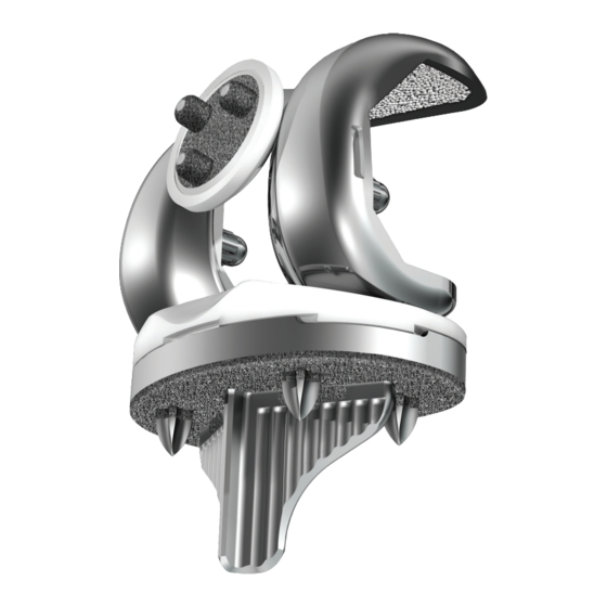
Page 6: Triathlon Tritanium Knee Construct
Triathlon Tritanium baseplate and compatible Triathlon Tritanium Metal-Backed Patellar component . Triathlon Tritanium Baseplate The Triathlon Tritanium baseplate is designed to be > similar to the Triathlon Primary baseplate . It offers the same profile and insert locking mechanism . - Page 7 9, 11, 13, 16 and 19mm, with additional available thicknesses of 22 and 25mm for the PS inserts . Triathlon primary inserts are available with > conventional polyethylene as well as Stryker’s X3 highly crosslinked polyethylene . Figure 3 Triathlon Tritanium Metal-Backed Patella The Triathlon Tritanium Metal-Backed Patella >...
-
Page 8: Femoral Preparation
Femoral Preparation Step 1 Distal Resection Exposure Triathlon Total Knee Arthroplasty can be performed > through any standard approach . A standard anterior mid-line incision or other suitable approaches such as mid-vastus, sub-vastus or quadriceps sparing may be used based on surgeon preference . Any previous incision can be used or incorporated to >... - Page 9 Instrument Bar Button 6541-4-801 Universal Driver Universal Resection Guide 6541-4-538 3/8˝ IM Drill Adjustment Block 6541-4-800 T-Handle Driver 6541-4-516 5/16˝ IM Rod Figure 8 6541-1-657 Femoral Alignment Guide Snap the Universal Resection Guide onto the > Adjustment Block and insert the posts of the Adjustment Block into the two holes in the Femoral Alignment Guide .
- Page 10 Femoral Preparation Step 1 Distal Resection (continued) The Adjustment Block allows for an 8mm (the distal > thickness of the femoral component) and 10mm (used to aid in the correction of a flexion contracture) resection level . Tip: The thickness of the resected femoral condyle should be measured .
- Page 11 Instrument Bar 6541-1-600 Adjustment Block 6541-1-657 Femoral Alignment Guide 6541-1-721 Figure 10 Universal Resection Guide Distal Resection 6541-4-806 After the Universal Resection Guide is pinned in Universal Alignment Handle > place, remove the IM Rod . The Femoral Alignment Guide and the Adjustment Block may be removed by squeezing the black tabs on the Adjustment Block .
-
Page 12: Step 2 Femoral Sizing
Femoral Preparation Step 2 Femoral Sizing Hole for Pin Assemble the Femoral Sizer with the Femoral Stylus > to Reference in the lateral hole (for both a left or right knee) and Whiteside’s Line set the stylus length to an approximate size . Set the rotation to LEFT for a left knee and RIGHT >... - Page 13 Instrument Bar 6541-1-603 Femoral Sizer 6541-1-605 Femoral Stylus 6541-4-003 Headless Pins – 3˝ Figure 14 6541-4-400 Bladerunner It is recommended that the anterior resection level be > checked to further confirm the correct size by sliding a Bladerunner through the sizing guide’s size-specific anterior slots and assessing the resection .
-
Page 14: Step 3 Anterior, Posterior And Chamfer Cuts
Femoral Preparation Step 3 Anterior, Posterior and Chamfer Cuts 4:1 Cutting Block Fixation Locate the fixation pegs of the appropriate size > Express 4:1 Cutting Block into the pin holes created on the distal femur . Note: Check run-out of the anterior cut . If not enough anterior bone is resected, consider selecting the next smaller size 4:1 Cutting Block . -
Page 15: Step 4 Ps Box Preparation
Femoral Preparation Instrument Bar Step 4 PS Box Preparation PS Box Preparation See Catalog If it is determined that a PS femoral component will Express 4:1 Cutting Block > be used, the distal femur must be prepared for the PS box . Place the appropriate sized PS Box Cutting Guide on the resected distal femur . - Page 16 Femoral Preparation Step 4 PS Box Preparation (continued) PS Box Cutting Guide Pin the PS Box Cutting Guide in place using > Headless Pins . Optional surgical tip: To provide the appropriate > anterior/posterior and medial/lateral stability with a minimal number of pins, place one pin distally and one pin anteriorly .
- Page 17 Instrument Bar See Catalog MIS PS Box Cutting Guide 6541-4-810 Impaction Handle 6541-4-709 Box Chisel Figure 19 See Catalog Triathlon PS Femoral Box Finishing Punch PS Box Preparation Option: Saw Only Option B: Saw Only: Use a narrow oscillating saw > through the proximal slot to resect the distal portion See Catalog of the femur .
- Page 18 Femoral Preparation Step 4 PS Box Preparation (continued) Optional PS Box Preparation Finishing Punch If the optional Triathlon PS Femoral Box Finishing Punch is chosen: The chisel should be fully removed from the PS > Box Cutting Guide prior to using the Triathlon PS Femoral Box Finishing Punch .
- Page 19 Instrument Bar See Catalog MIS PS Box Cutting Guide 6541-4-810 Impaction Handle 6541-4-709 Box Chisel Figure 23 PS Box Femoral Box Trial/Protector See Catalog If the optional and recommended Triathlon PS Triathlon PS Femoral Box Finishing Punch > Femoral Box Trial/Protector is chosen: •...
- Page 20 Femoral Preparation Step 4 PS Box Preparation (continued) Femoral Box Protection During Tibia Subluxation To protect the prepared femoral box prior to trialing > with a femoral component, place the Triathlon PS Femoral Box Trial/Protector into the prepared box by hand (not through impaction) . Ensure the box trial is fully seated on the distal and >...
-
Page 21: Step 5 Femoral Trial Assessment
Femoral Preparation Instrument Bar Step 5 Femoral Trial Assessment See Catalog MIS PS Box Cutting Guide See Catalog Triathlon PS Femoral Box Trial/Protector 6541-4-003 Headless Pins – 3˝ 6541-4-809 Figure 26 Headless Pin Driver 6541-4-810 The remaining portion of the technique is for both Posterior >... - Page 22 Femoral Preparation Step 5 Femoral Trial Assessment (continued) Cruciate Retaining Knee: Attach the 1/4˝ Peg Drill > to the Universal Driver and create the Modular Femoral Distal Fixation Peg holes . Attach the Posterior Osteophyte Removal Tool to the > Impaction Handle and remove posterior osteophytes .
- Page 23 Instrument Bar 6541-4-801 Universal Driver See Catalog CR Femoral Trial See Catalog PS Femoral Trial Figure 28 6541-4-525 1/4˝ Peg Drill To remove the Femoral Trial, attach the Femoral 6541-4-803 > Impactor Extractor to the Slap Hammer and remove Slap Hammer the PS or CR Femoral Trial from the femur .
-
Page 24: Tibial Preparation
Tibial Preparation Step 1A Tibial Preparation: Extramedullary (EM) Referencing Tibial Resection Assembly Fixation The Tibial Resection Guide, available in left and right > configurations, and the Universal Resection Guide Locking are designed to avoid soft tissue impingement . Switch The tibial resection assembly has five parts: the >... - Page 25 Instrument Bar Right 6541-2-700 Fixation Left 6541-2-701 Tibial Resection Guide Locking Switch 6541-2-610 Tibial Alignment Distal Assembly EM 6541-2-609 (6541-2-611 Tibial Tibial Alignment Ankle Clamp EM Alignment Proximal Rod EM) Figure 32 6541-2-611 Tibial Alignment Proximal Rod EM Rotational Alignment Rotate the entire assembly to ensure that the base of >...
-
Page 26: Step 1B Tibial Preparation: Intramedullary (Im) Referencing
Tibial Preparation Step 1B: Tibial Preparation: Intramedullary (IM) Referencing Attach the 3/8˝ IM Drill to the Universal Driver and > create a hole in the location determined by the pre- operative X-rays to align with the IM canal . Figure 33 Attach the T-Handle Driver to the 5/16˝... - Page 27 Instrument Bar 6541-4-538 3/8˝ IM Drill 6541-4-801 Universal Driver 6541-4-800 T-Handle Driver ( Tibial Resection 6541-4-516 Guide shown) 5/16˝ IM Rod Figure 36 6541-2-600 Varus/Valgus Alignment Tibial Alignment Jig IM Assemble the appropriate Tibial Resection Guide > (left, right or Universal Resection Guide) on the Tibial Adjustment Housing .
-
Page 28: Step 2 Tibial Resection
Tibial Preparation Step 2 Tibial Resection The following applies to both extramedullary and intramedullary alignment . Establish Tibial Resection Level The Tibial Stylus attaches to the Tibial Resection > Guide or Universal Resection Guide with the “9” end referencing the lowest level of the unaffected compartment . - Page 29 Instrument Bar 6541-2-611E Express Proximal Rod EM 6541-2-611 Tibial Alignment Proximal Rod EM Right 6541-2-700 Left 6541-2-701 Tibial Resection Guide 0º slope 6541-2-704 3º slope 6541-2-705 Figure 39 Tibial Adjustment Housing 6541-4-806 Universal Alignment Handle Tibial Component Sizing Place the PS or CR Femoral Trial on the femur . Draw >...
- Page 30 Tibial Preparation Step 2 Tibial Resection (continued) There are two options to secure the Universal Tibial Template to the tibia: Securing Tibial Template Option 1: Once satisfactory alignment and tibial component > orientation are achieved, place pins through the two anterior holes of the Universal Tibial Template to secure its position .
-
Page 31: Step 3 Tibial Keel Punch
Tibial Preparation Instrument Bar Step 3 Tibial Keel Punch See Catalog Universal Tibial Template Lock See Catalog CR & PS Femoral Trials 6541-4-003 Headless Pins – 3˝ Figure 41 Size 1, 2, 3 – 6541-2-713 Securing Tibial Keel Punch Guide Size 4, 5, 6, 7, 8 –... - Page 32 Tibial Preparation Step 3 Tibial Keel Punch (continued) Tibial Keel Punching Place the appropriate Cementless Keel Punch into > the Keel Punch Guide . Use a mallet to impact the Keel Punch . > Tip: The presence of variably dense bone in the proximal tibia can influence the advancement of the Keel Punch .
- Page 33 Instrument Bar See Catalog Universal Tibial Template 6541-4-003 Headless Pins – 3˝ Size 1, 2, 3 – 6541-2-713 Size 4, 5, 6, 7, 8 – 6541-2-748 Keel Punch Guide Figure 43 See Catalog Cementless Keel Punch Extracting Keel Punch To extract the Keel Punch, lift up on the Keel Punch >...
-
Page 34: Patella Preparation
Patella Preparation Patella Resection Patella preparation is optional and is based on > surgeon preference and surgeon evaluation of the articulating surface . Remove all osteophytes and synovial insertions > around the patella, and measure thickness using a caliper . After determining the depth of the cut, affix the >... -
Page 35: Trial Assessment
Trial Assessment Instrument Bar 6633-7-744 Patella Clamp 6633-7-738 Patella Stylus 6633-7-736 Slotted Patella Resection Guide Figure 46 See Catalog Express Symmetric & Asymmetric Patella Drill Templates Remove any residual cartilage and wash away all > debris . Place correct size Patella Trial (Symmetric or >... -
Page 36: Tibial Preparation (Continued)
Tibial Preparation Step 4 Tibial Peg Preparation Tibial Peg Drill Template Note: Universal Tibial Template, Keel Punch Tower, Keel Punch and all pins need to be removed from tibia before tibial peg preparation . Select the Tibial Peg Drill Template that corresponds >... - Page 37 Instrument Bar 6541-4-801 Universal Driver 1/8˝ Tibial Peg Drill (6541-2-625) 6541-2-64X – See Catalog Figure 50 Tibial Peg Drill Template 6541-2-625 1/8˝ Tibial Peg Drill Figure 51 Drilling for Pegs Drill Selection: Drilling the tibial peg holes will facilitate seating the >...
- Page 38 Tibial Preparation Step 4 Tibial Peg Preparation (continued) Image of the Tibia After Tibial Preparation Figure 52...
- Page 39 Tibial Preparation Instrument Bar Step 4 Tibial Peg Preparation 6541-4-801 Universal Driver 7/32˝ Tibial Peg Drill (6541-2-626) 6541-2-626 7/32˝ Tibial Peg Drill Figure 53 Figure 54 Optional: Drilling with the 7/32˝ Peg Drill If the surgeon feels the bone is too dense at any of the peg >...
-
Page 40: Femoral Implantation
Femoral Implantation Attach the Femoral Impactor Extractor to the > Impaction Handle and attach to the appropriate size and side Femoral Component . Place the Femoral Component on the femur and impact it until fully seated . Posterior Stabilized Knee: If Modular Femoral Distal >... -
Page 41: Tibial Implantation
Baseplate with or without cement . If Cementless: Connect the Tibial Baseplate Impactor/Extractor to the > Impaction Handle Connect the Tibial Baseplate Impactor/Extractor to the > Triathlon Tritanium Baseplate over the Impactor Pad and lock the lever... - Page 42 Tibial Implantation (continued) Baseplate Impaction Caution: Pegs on the Triathlon Tritanium Tibial Baseplate are sharp . Take care when handling the baseplate . Tip: At this stage, cysts or voids on the surface of the tibia may be bone grafted with local resected cancellous bone .
-
Page 43: Tibial Insert Implantation
Tritanium Baseplate . The posterior lip of the Size 4-6 – 6541-2-046 Tibial Insert must fit beneath the lip on the Cemented Keel Punch posterior Triathlon Tritanium Baseplate wall . Attach the Tibial Insert Impactor to the > Impaction Handle and impact to snap the Insert in place anteriorly . -
Page 44: Patella Implantation
Patella Implantation Assembling the Patella Implant to the Patella Capture Select the Patella Capture that corresponds to the > size of the patella to be implanted and snap the polyethylene side of the patella implant to the Lateral Medial capture . Note: If an asymmetric patella and Capture are selected, place the medial side of the patella in first and then snap in the lateral side . - Page 45 Patella Implantation Instrument Bar (continued) 6541-3-530 Patella Inserter See Catalog Symmetric Tritanium Patella Capture Figure 63 Turn the T-handle of the Patella Inserter until the metal backing portion of the > See Catalog patella implant is fully seated onto the resected surface of the native patella . Asymmetric Tritanium Patella Capture Note: The metal backing portion of the patella implant protrudes slightly from the peripheral polyethylene surface .
-
Page 46: Product Dimensions
(mm) (mm) (mm) (Proximal) (mm) (mm) 5536-B-100 5536-B-200 5536-B-300 5536-B-400 5536-B-500 5536-B-600 5536-B-700 5536-B-800 Triathlon Tritanium Metal-Backed Symmetric Patella Diameter Thickness Part No. Size (mm) (mm) 5556-L-319 5556-L-339 5556-L-360 5556-L-391 Triathlon Tritanium Metal-Backed Asymmetric Patella S/I* Diameter M/L Width Thickness Part No. -
Page 47: Catalog
Catalog Catalog # Description Quantity in Kit Miscellaneous Instruments Kit Contents 3170-0000 1/8˝ Drill 6541-4-003 Headless Pins – 3˝ 6541-4-300 Headed Nail Impactor Extractor (Optional) 6541-4-400 Bladerunner 6541-4-515 Headed Nails – 1½˝ (Optional) 6541-4-516 5/16˝ IM Rod* 6541-4-518 1/8˝ Peg Drill 6541-4-525 1/4˝... - Page 48 Catalog Catalog # Description Quantity in Kit Patella Preparation & Trialing Part Numbers 6633-7-736 Slotted Patella Resection Guide 6633-7-738 Patella Stylus 7650-1454 Patella Caliper 6541-3-524 All-Poly Patella Drill w/Stop 6541-3-617E Express Asymmetric Patella Drill Template – 29mm 6541-3-618E Express Asymmetric Patella Drill Template – 33mm 6541-3-619E Express Asymmetric Patella Drill Template –...
- Page 49 Triathlon Cementless Keel Punch 1 Each Size 6541-6-078 Triathlon Cementless Keel Punch 1 Each Size For Tibial Peg Preparation, please use the Triathlon Tritanium Baseplate Instrumentation below: 6541-8-100 Triathlon Tritanium Prep Tray 6541-2-64X Tritanium Tibial Peg Drill Template X= 1,2,3,4,5,6,7 and 8...
- Page 50 Catalog Catalog # Description Quantity in Kit Size 3-6 Femoral & Tibial Preparation Kit Contents 6541-1-600 Adjustment Block 6541-1-603 Femoral Sizer 6541-1-605 Femoral Stylus 6541-1-657 Femoral Alignment Guide 6541-1-703E #3 Express 4:1 Cutting Block 6541-1-704E #4 Express 4:1 Cutting Block 6541-1-705E #5 Express 4:1 Cutting Block 6541-1-706E...
- Page 51 Catalog # Description Quantity in Kit Size 3-6 PS Femoral & Tibial Trialing Kit Contents 5511-T-301 PS Femoral Trial #3 Left 5511-T-302 PS Femoral Trial #3 Right 5511-T-401 PS Femoral Trial #4 Left 5511-T-402 PS Femoral Trial #4 Right 5511-T-501 PS Femoral Trial #5 Left 5511-T-502 PS Femoral Trial #5 Right...
- Page 52 Catalog Catalog # Description Quantity in Kit Size 3-6 CR Femoral & Tibial Trialing Kit Contents 5510-T-301 CR Femoral Trial #3 Left 5510-T-302 CR Femoral Trial #3 Right 5510-T-401 CR Femoral Trial #4 Left 5510-T-402 CR Femoral Trial #4 Right 5510-T-501 CR Femoral Trial #5 Left 5510-T-502...
- Page 53 Catalog # Description Quantity in Kit Size 1, 8 PS Preparation & Trialing Kit Contents 5511-T-101 PS Femoral Trial #1 Left 5511-T-102 PS Femoral Trial #1 Right 5511-T-801 PS Femoral Trial #8 Left 5511-T-802 PS Femoral Trial #8 Right 5532-T-109A PS Tibial Insert Trial #1 –...
- Page 54 Catalog Catalog # Description Quantity in Kit Size 1, 8 CR Preparation & Trialing Kit Contents 5510-T-101 CR Femoral Trial #1 Left 5510-T-102 CR Femoral Trial #1 Right 5510-T-801 CR Femoral Trial #8 Left 5510-T-802 CR Femoral Trial #8 Right 5530-T-109A CR Tibial Insert Trial #1 –...
- Page 55 Catalog # Description Quantity in Kit Size 2, 7 CR Preparation & Trialing Kit Contents 5510-T-201 CR Femoral Trial #2 Left 5510-T-202 CR Femoral Trial #2 Right 5510-T-701 CR Femoral Trial #7 Left 5510-T-702 CR Femoral Trial #7 Right 5530-T-209A CR Tibial Insert Trial #2 –...
- Page 56 Catalog Catalog # Description Sizes Triathlon CR Modified Hollow Tibial Insert Trials Part Numbers 5530-T-X09A CR Modified Hollow Tibial Insert Trial 9mm X = 1,2,3,4,5,6,7 and 8 1 Each Size 5530-T-X11A CR Modified Hollow Tibial Insert Trial 11mm X = 1,2,3,4,5,6,7 and 8 1 Each Size 5530-T-X13A CR Modified Hollow Tibial Insert Trial 13mm...
- Page 57 Triathlon Tritanium Baseplate 5536-B-X00 Triathlon Tritanium Baseplate X= 1,2,3,4,5,6,7,8 1 Each Size Please note: Each Triathlon Tritanium Baseplate will be provided packaged together with an Impactor Pad (6541-4-901) which is required during the tibial baseplate impaction step and discarded immediately after .
- Page 58 Catalog Catalog # Description Sizes Triathlon CR Tibial Inserts – Conventional Polyethylene and X3 Part Numbers Conventional Polyethylene Inserts 5530-P-X09 Triathlon CR Tibial Insert – Conventional Polyethylene 9mm X = 1,2,3,4,5,6,7 and 8 1 Each Size 5530-P-X11 Triathlon CR Tibial Insert – Conventional Polyethylene 11mm X = 1,2,3,4,5,6,7 and 8 1 Each Size 5530-P-X13...
- Page 59 Catalog # Description Sizes Triathlon CS Tibial Inserts – Conventional Polyethylene and X3 Part Numbers Conventional Polyethylene Inserts 5531-P-X09 Triathlon CS Tibial Insert – Conventional Polyethylene 9mm X = 1,2,3,4,5,6,7 and 8 1 Each Size 5531-P-X11 Triathlon CS Tibial Insert – Conventional Polyethylene 11mm X = 1,2,3,4,5,6,7 and 8 1 Each Size 5531-P-X13...
- Page 60 Catalog Catalog # Description Sizes Symmetric Patella – Conventional Polyethylene and X3 Part Numbers Conventional Polyethylene Patellas 5550-L-278 Symmetric Patella – Conventional Polyethylene S27mm x 8mm 5550-L-298 Symmetric Patella – Conventional Polyethylene S29mm x 8mm 5550-L-319 Symmetric Patella – Conventional Polyethylene S31mm x 9mm 5550-L-339 Symmetric Patella –...
- Page 61 Catalog # Description Sizes Asymmetric Patella – Metal-Backed Beaded w/ Peri-Apatite Conventional Polyethylene Patellas 5554-L-320 Asymmetric Patella – Metal-Backed Beaded with Peri-Apatite A32mm (S/I*) x 10mm 5554-L-350 Asymmetric Patella – Metal-Backed Beaded with Peri-Apatite A35mm (S/I*) x 10mm 5554-L-381 Asymmetric Patella – Metal-Backed Beaded with Peri-Apatite A38mm (S/I*) x 11mm 5554-L-401 Asymmetric Patella –...
- Page 62 Triathlon Tritanium Surgical Protocol with Triathlon Cementless Beaded PA Femoral Component Notes...
- Page 63 Triathlon Tritanium Surgical Protocol with Triathlon Cementless Beaded PA Femoral Component Notes...
- Page 64 Triathlon Tritanium Surgical Protocol with Triathlon Cementless Beaded PA Femoral Component Notes...
- Page 65 Femoral Component/ Insert Type Insert Compatibility Size Matching: One up, one down, e .g ., Femoral Components size 5 femur with size 4 or 6 insert/ baseplate . CR Cemented Note: Cementless implants are not to be PS Cemented used with cement . TS Cemented CR Beaded PS Beaded...
- Page 66 The information presented is intended to demonstrate the breadth of Stryker product offerings . A surgeon must always refer to the package insert, product label and/or instructions for use before using any Stryker product . The products depicted are CE marked according to the Medical Device Directive 93/42/EEC . Products may not be available in all markets because product availability is subject to the regulatory and/or medical practices in individual markets .
Need help?
Do you have a question about the Triathlon Tritanium and is the answer not in the manual?
Questions and answers
what metals are in the triathlon tritanium 7 tibial knee implant model 5536-B-700