
Related Manuals for Miller ArcStation


Summary of Contents for Miller ArcStation
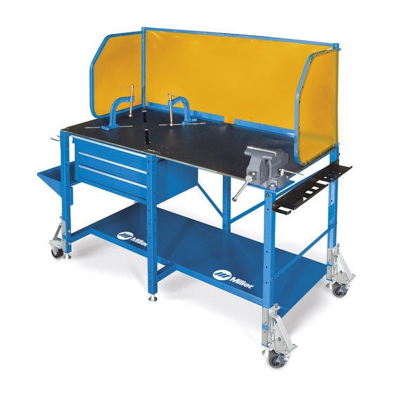
- Page 1 OM-247318E 2018−12 Place serial number or lot code sticker here. ArcStation Accessories File: Accessory For product information, Owner’s Manual translations, and more, visit www.MillerWelds.com...
- Page 2 1929, he made sure his products offered long-lasting value and superior quality. Like you, his customers couldn’t afford anything less. Miller products had to be more than the best they could be. They had to be the best you could buy.
-
Page 3: Table Of Contents
TABLE OF CONTENTS SECTION 1 − SAFETY PRECAUTIONS − READ BEFORE USING ....... . . 1-1. -
Page 5: Section 1 − Safety Precautions − Read Before Using
SECTION 1 − SAFETY PRECAUTIONS − READ BEFORE USING weld table_2018-01 Protect yourself and others from injury — read, follow, and save these important safety precautions and operating instructions. 1-1. Symbol Usage DANGER! − Indicates a hazardous situation which, if Indicates special instructions. -
Page 6: Section 2 − Consignes De Sécurité − Lire Avant Utilisation
SECTION 2 − CONSIGNES DE SÉCURITÉ − LIRE AVANT UTILISATION weld table_2018-01_fre Pour écarter les risques de blessure pour vous−même et pour autrui — lire, appliquer et ranger en lieu sûr ces consignes relatives aux précautions de sécurité et au mode opératoire. 2-1. -
Page 7: Section 3 − Accessories
SECTION 3 − ACCESSORIES 3-1. Hardware Description 247 341-B OM-247318 Page 3... -
Page 8: Installing Tool Chest Under X-Pattern Top
3-2. Installing Tool Chest Under X-Pattern Top Removing Dust Tray And Rails Skip this section if dust tray is not present. Remove dust tray from rails as follows: Dust Tray Dust Tray Rails S Remove dust tray from rails. S Slide tray out. S Lift front of tray up. -
Page 9: Installing Tool Chest Under Solid Top
3-3. Installing Tool Chest Under Solid Top For solid top, use brackets and hardware that came with the tool chest. Brackets Tool Chest Use four bolts CC that came with the tool chest and install brackets to top of tool chest. Do not tighten bolts at this time. -
Page 10: Installing Dust Tray
3-4. Installing Dust Tray Dust Tray Rails Use the supplied four bolts AA and four locknuts ZZ and install dust tray rails to the welding table. Be sure that dust tray rails are on the inside of the subframe assemblies. Tighten all bolts and locknuts. -
Page 11: Installing Vise Kit
3-5. Installing Vise Kit Vise Mount Place both vise mount and vise on a solid surface to prevent them from falling. Use the supplied four bolts JJ, four lock washers WW, and four nuts XX and install vise to the vise mount. Remove tube cap from end subframe tube. -
Page 12: Installing Convenience Kit Gun Holder
3-6. Installing Convenience Kit Gun Holder Gun Holder Gun holder will mount to any hole in the subframe except the top hole. If installing gun holder Tools Needed: with a dust tray or tool chest, place locknut on outside of 1/2 in. -
Page 13: Installing Convenience Kit Clamp Bar
3-8. Installing Convenience Kit Clamp Bar Clamp Bar Mounting Hole Selection Select the desired side of the weld- ing table to install the clamp bar. Tools Needed: Use two supplied bolts EE and locknuts ZZ to secure clamp bar to 1/2 in. -
Page 14: Installing Exterior Shelf
3-9. Installing Exterior Shelf load shelf until stabilizer bracket is installed and leveling foot is adjusted so that table is level. Stabilizer Bracket Leveling Foot EE and ZZ Install leveling foot in bottom of stabilizer bracket. Use supplied bolt EE and nut ZZ in the top hole and bolt CC in the bottom hole, and install stabilizer bracket to side leg of end subframe. -
Page 15: And 60Sx Weld Curtain
3-10. 60S And 60SX Weld Curtain Corner Post When securing corner post to table, bolt from back side of table. Tools Needed: Remove the two rear tube caps. In- 9/16 in. sert corner post into each rear tube and use the supplied two bolts FF to secure corner posts. -
Page 16: Installing Caster Assembly
3-11. Installing Caster Assembly Casters are only for moving ta- The 30S and 30SX welding table cannot ble. Do not work on table with use caster mounts with an external shelf. casters extended. Remove external shelf before installing caster mounts. If the leveling foot mounting bolt is installed on the outside hole, remove and install on the inside... - Page 19 Effective January 1, 2018 (Equipment with a serial number preface of MJ or newer) This limited warranty supersedes all previous Miller warranties and is exclusive with no other guarantees or warranties expressed or implied. Warranty Questions? LIMITED WARRANTY − Subject to the terms and conditions below, 6 Months —...
- Page 20 Contact the Delivering Carrier to: File a claim for loss or damage during shipment. For assistance in filing or settling claims, contact your distributor and/or equipment manufacturer’s Transportation Department. ORIGINAL INSTRUCTIONS − PRINTED IN USA 2018 Miller Electric Mfg. LLC 2018−01...
Need help?
Do you have a question about the ArcStation and is the answer not in the manual?
Questions and answers