Advertisement
Quick Links
BE SURE POWER IS DISCONNECTED PRIOR TO INSTALLATION!
FOLLOW NATIONAL, STATE, AND LOCAL CODES!
READ THESE INSTRUCTIONS ENTIRELY BEFORE INSTALLATION!
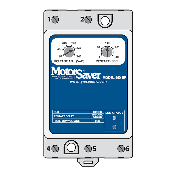
The Model 460-SP MotorSaver
single-phase motors regardless of size. The MotorSaver
240 (95-120) VAC, 50 to 60 Hz motors to protect from damage caused by low
voltage and high voltage.
CONNECTIONS
1. Mount the MotorSaver
control panel. If the location is wet or dusty, the MotorSaver
be mounted in a NEMA 4 or 12 enclosure. The MotorSaver
mounted to a back panel using two #6 or #8 x 5/8 screws or can be
snapped onto a DIN rail.
2. Connect L1 and L2 on the MotorSaver's terminal strip to the LINE SIDE
of the motor starter (See Figure 1).
3. Connect the output relay to the circuitry to be controlled. For motor control,
connect the normally open contact in series with the magnetic coil of the
motor starter (See Figure 1). For alarm operation, connect the
normally closed contact in series with the control circuit (See Figure 2).
Phone: 800.894.0412 - Fax: 888.723.4773 - Web: www.clrwtr.com - Email: info@clrwtr.com
INSTALLATION INSTRUCTIONS
FOR SYMCOM'S MOTORSAVER
is a voltage monitor designed to protect
in a convenient location in or near the motor
MODEL 460-SP
is used on 190-
should
can be
Advertisement

Related Manuals for SymCom Motor Saver 460-SP


Summary of Contents for SymCom Motor Saver 460-SP
- Page 1 INSTALLATION INSTRUCTIONS FOR SYMCOM’S MOTORSAVER MODEL 460-SP BE SURE POWER IS DISCONNECTED PRIOR TO INSTALLATION! FOLLOW NATIONAL, STATE, AND LOCAL CODES! READ THESE INSTRUCTIONS ENTIRELY BEFORE INSTALLATION! The Model 460-SP MotorSaver is a voltage monitor designed to protect ...
- Page 2 460-SP CONTROL VOLTAGE 24-240 VAC FIGURE 1: CONTROL WIRING DIAGRAM 460-SP CONTROL VOLTAGE LIGHT 24-240 VAC FIGURE 2: ALARM WIRING DIAGRAM Phone: 800.894.0412 - Fax: 888.723.4773 - Web: www.clrwtr.com - Email: info@clrwtr.com...
- Page 3 SETTINGS 1. Line voltage adjustment: Rotate the “VOLTAGE ADJ. (VAC)” to the nominal line voltage feeding the motor to be protected. 2. Restart delay adjustment: Rotate the “RESTART (SEC)” adjustment to the desired position. The restart delay is the time between the MotorSaver® seeing acceptable voltage and the MotorSaver®...
-
Page 4: Diagnostic Indicator Lights
POWER-UP Turn on the power to the motor. The MotorSaver’s green RUN light will blink during the RESTART delay. After the RESTART delay, the MotorSaver will ® energize its output contacts and the green RUN light will illuminate. If the contacts do not energize and the RUN light does not illuminate, see the TROUBLESHOOTING section. -
Page 5: Troubleshooting
The unit seems N / A tronics. completely dead. If the voltage is correct, call SymCom at 1-800-843-8848 or 1-605-348-5580. The voltage is out of tolerance. Measure the input voltage. If the voltage is 7% above or below the nominal voltage as selected... -
Page 6: Specifications
SPECIFICATIONS 1 - Phase Line Voltage 190 - 240 (95-120) VAC Frequency 50* - 60 Hz High Voltage (% of setpoint) Trip 110% ±1% Reset 107% ±1% Low Voltage (% of setpoint) Trip 90% ±1% Reset 93% ±1% Trip Delay Time Low Voltage 4 Seconds Fixed High Voltage... - Page 7 (5) years* from the date of manufacture. All other products manufactured by SymCom shall be warranted against defects in material and workmanship for a period of two (2) years from the date of manufacture. For complete information on warranty, liability, terms, and conditions, please refer to the SymCom Terms and Conditions of Sale document.
Need help?
Do you have a question about the Motor Saver 460-SP and is the answer not in the manual?
Questions and answers