
Related Manuals for Gemu GEMU 1242


Summary of Contents for Gemu GEMU 1242
- Page 1 GEMÜ 1242 DeviceNet Electrical position indicator Operating instructions 4009951 4009951 further information webcode: GW-1242...
- Page 2 All rights including copyrights or industrial property rights are expressly reserved. Keep the document for future reference. © GEMÜ Gebr. Müller Apparatebau GmbH & Co. KG 12.04.2019 GEMÜ 1242 2 / 32 www.gemu-group.com DeviceNet...
-
Page 3: Table Of Contents
15 Disassembly ............. 27 16 Disposal ..............27 17 Returns ..............27 18 Declaration of conformity according to 2014/30/EU (EMC Directive) ............28 19 Declaration of conformity in accordance with 2014/34/EU (ATEX) ........... 29 3 / 32 www.gemu-group.com GEMÜ 1242 DeviceNet... -
Page 4: General Information
Warning notes are always marked with a signal word and sometimes also with a symbol for the specific danger. The following signal words and danger levels are used: DANGER Imminent danger! ▶ Non-observance can cause death or severe injury. WARNING Potentially dangerous situation! ▶ Non-observance can cause death or severe injury. GEMÜ 1242 4 / 32 www.gemu-group.com DeviceNet... - Page 5 ▶ Non-observance can cause moderate to light injury. NOTICE Potentially dangerous situation! ▶ Non-observance can cause damage to property. The following symbols for the specific dangers can be used within a warning note: Symbol Meaning Danger from potentially explosive atmosphere www.gemu-group.com 5 / 32 GEMÜ 1242 DeviceNet...
-
Page 6: Safety Information
13. Maintain the product correctly. 14. Do not carry out any maintenance work and repairs not described in this document without consulting the manufacturer first. In cases of uncertainty: 15. Consult the nearest GEMÜ sales office. GEMÜ 1242 6 / 32 www.gemu-group.com DeviceNet... -
Page 7: Product Description
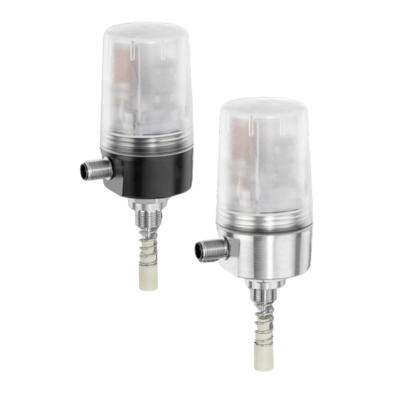
3 Product description 3.1 Construction Item Name Materials Housing cover - standard version: Housing base Anodised aluminium or SS Electrical connection SS, PP Adapter piece Mounting kit, valve specific Seals EPDM and NBR www.gemu-group.com 7 / 32 GEMÜ 1242 DeviceNet... - Page 8 The current position of the valve is displayed via high visibility LEDs and fed back via electrical signals. The GEMÜ 1242 has been specially designed for valves with a stroke of 2 to 46 mm. GEMÜ 1242 8 / 32 www.gemu-group.com DeviceNet...
-
Page 9: Correct Use
The device must only be used if its materials are resistant against mechanical and/or chemical influences or corrosion under the respective operating conditions to such a sufficient degree that the explosion protection is not impaired or nullified. www.gemu-group.com 9 / 32 GEMÜ... - Page 10 1. Connection cables and connectors must be protected from damage. 2. Layers of dust > 5 mm must be removed. 3. Warning label "Danger from electrostatic build-up". 4. Warning label "Do not disconnect when live". GEMÜ 1242 10 / 32 www.gemu-group.com DeviceNet...
-
Page 11: Order Data
Position feedback Open / Closed 6 Electrical connection M12 plug, 5-pin 7 Option Without 8 Switch Electronics 9 Connection diagram M12 plug, 5-pin 10 Special version Without 11 / 32 11 / 32 www.gemu-group.com www.gemu-group.com GEMÜ 1242 GEMÜ 1242 DeviceNet DeviceNet... -
Page 12: Technical Data
0.2 Full Scale 6.4 Electrical data Supply voltage Uv: 11 to 25 V DC Duty cycle: Continuous duty Reverse battery protection: Current consumption: typically 30 mA Electrical connection 1 x 5-pin M12 plug (A-coded) type: GEMÜ 1242 12 / 32 www.gemu-group.com DeviceNet... -
Page 13: Dimensions
Electrical protection class: 7 Dimensions Ø57 WAF 20 for mounting kit M12x1, x = 9 mm WAF 24 for mounting kit M16x1, x = 11 mm 16,6 dependent on valve used Dimensions in mm www.gemu-group.com 13 / 32 GEMÜ 1242 DeviceNet... -
Page 14: Manufacturer's Information
5. Lay cables securely and protect them from damage. 6. Differential voltage for two intrinsically safe electric circuits: Maximum 30 V. 7. Connect open wire ends in a junction box with protection class IP20 and higher or outside the EX area. GEMÜ 1242 14 / 32 www.gemu-group.com DeviceNet... - Page 15 1. Pull out the spindle 1. 2. Align the indentation of the distance piece 4 to the spring and push it over the spindle 1 using the spring 2 and fix it in place using the operating bush 3. www.gemu-group.com 15 / 32 GEMÜ 1242...
- Page 16 Insert the O-ring 11 (if included) into the corresponding groove If included: Push the pressure disc 9 over the adapter 6 and on the adapter 6. insert the O-ring 10 in the intended groove of the pressure disc. GEMÜ 1242 16 / 32 www.gemu-group.com DeviceNet...
-
Page 17: Assembling And Installing The Electrical Position Indicator
▶ Danger of death or severe injury. Do not use the product as a step or foothold. ● Prior to commissioning, ensure that the cover is fully closed and that the housing and the O-ring are not ● damaged. www.gemu-group.com 17 / 32 GEMÜ 1242 DeviceNet... - Page 18 Only tighten the product using the spanner flats provided for this purpose. ● 5. The product with mounting kit is fully assembled. 6. The product with mounting kit and adapter is fully assembled. GEMÜ 1242 18 / 32 www.gemu-group.com DeviceNet...
-
Page 19: Electrical Connection
1. Use a screw M4x6 to attach the potential equalisation device to the electrical position indicator. ð Potential equalisation for metal housings in potentially explosive areas: Minimum 4 mm². 2. Secure the connection against working itself loose. www.gemu-group.com 19 / 32 GEMÜ 1242... -
Page 20: Devicenet, Ordering Option Fieldbus, Code Dn
Thick cable Thin cable Max. cable length per Max. drop cable accu- drop cable mulated length 500 m 100 m 156 m 250 m 100 m 78 m 100 m 100 m 39 m GEMÜ 1242 20 / 32 www.gemu-group.com DeviceNet... - Page 21 3. Refer to the technical data and cable gland documentation for details of the wire cross sections. 4. Protect the product and the cables from damage. 5. Only clean the product with an anti-static or damp cloth. 6. Only operate the product when it is fully assembled. www.gemu-group.com 21 / 32 GEMÜ 1242 DeviceNet...
-
Page 22: Programming The End Positions
7. Open valve until end position is reached. 8. Close valve until end position is reached. 9. Set output bit 5 = 0. (electrical position indicator in normal operation) ð The end positions are set. GEMÜ 1242 22 / 32 www.gemu-group.com DeviceNet... -
Page 23: Specific Data - Devicenet
Device status according to DeviceNet specifications Series No. Continuous serial number Name 1242 DN position indicator 1) Use EDS file in accordance with revision status of the device Note: Download EDS files from www.gemu-group.com 12.1 Inputs Default Designation Function Logic... -
Page 24: Parameter
Valve position 2 byte UINT Display of numerical values 0 - 4092 Sensor error 1 byte USINT 0 = Sensor OK 1 = Sensor error position closed 2 = Sensor error position open GEMÜ 1242 24 / 32 www.gemu-group.com DeviceNet... - Page 25 3 = Stroke reduction position closed + open Valve cycles user 4 byte UDINT Get/Set 0 Resettable to 0, display of numerical values 0 - 429496729 Valve cycles total 4 byte UDINT Display of numerical values 0 - 429496729 www.gemu-group.com 25 / 32 GEMÜ 1242 DeviceNet...
-
Page 26: Error Clearance
"Technical data") Supply voltage too low Supply voltage < 18 V DC Ensure supply voltage (see "Technical data") Internal error Memory error Re-programme The spring locks during installation Mounting kit too long Contact GEMÜ 26 / 32 GEMÜ 1242 www.gemu-group.com DeviceNet... -
Page 27: Inspection And Servicing
GEMÜ cannot process credits or repair work but will dispose of the goods at the op- erator's expense. 1. Clean the product. 2. Request a return delivery note from GEMÜ. 3. Complete the return delivery note. 4. Send the product with a completed return delivery note to GEMÜ. www.gemu-group.com 27 / 32 GEMÜ 1242 DeviceNet... -
Page 28: Declaration Of Conformity According To 2014/30/Eu (Emc Directive)
24 V DC, IO-Link, DeviceNet: EN 61000-6-2 AS-Interface: acc. to AS-Interface Spec. 3.0 – Interference emission: 24 V DC, IO-Link, DeviceNet: EN 61000-6-3 AS-Interface: acc. to AS-Interface Spec. 3.0 Ingelfingen-Criesbach 29-05-2018 Joachim Brien Head of Technical Department 28 / 32 GEMÜ 1242 www.gemu-group.com DeviceNet... -
Page 29: Declaration Of Conformity In Accordance With 2014/34/Eu (Atex)
The Essential Safety and Health Requirements are met by compliance with the standards listed below that are applicable for the above mentioned product: – DIN EN 60079-0:2012+A11:2013 – DIN EN 60079-7:2015 – DIN EN 60079-15:2010 – DIN EN 60079-31:2014 Ingelfingen-Criesbach 29-05-2018 Joachim Brien Head of Technical Department 29 / 32 www.gemu-group.com GEMÜ 1242 DeviceNet... - Page 30 30 / 32 GEMÜ 1242 DeviceNet...
- Page 31 31 / 32 GEMÜ 1242 DeviceNet...
- Page 32 GEMÜ Gebr. Müller Apparatebau GmbH & Co. KG Subject to alteration Fritz-Müller-Straße 6-8, 74653 Ingelfingen-Criesbach, *88585870* Germany 04.2019 | 88585870 Tel. +49 (0)7940 123-0 · info@gemue.de www.gemu-group.com...
Need help?
Do you have a question about the GEMU 1242 and is the answer not in the manual?
Questions and answers