Advertisement
Quick Links
This document set is applicable to the following part number configurations:
Part Number
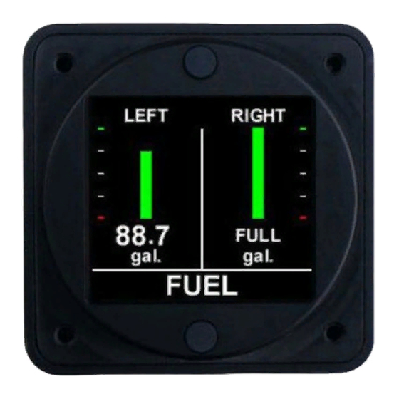
Fuel level instrument, two tanks,
FL202
Part Number
Fuel level instrument, three tanks,
FL203
Part Number
Fuel level instrument, four tanks,
FL204
Part Number
Fuel level instrument, five tanks,
FL205
Part Number
Fuel level instrument, six tanks,
FL206
Aerospace Logic Inc.
Tel. 416-628-0725
www.aerospacelogic.com
Description
resistive senders
Description
resistive senders
Description
resistive senders
Description
resistive senders
Description
resistive senders
Advertisement

Summary of Contents for Aerospace Logic FL20 Series
- Page 1 Part Number Description Fuel level instrument, four tanks, FL204 resistive senders Part Number Description Fuel level instrument, five tanks, FL205 resistive senders Part Number Description Fuel level instrument, six tanks, FL206 resistive senders Aerospace Logic Inc. Tel. 416-628-0725 www.aerospacelogic.com...
- Page 2 Canadian STC and Eligibility List STC & S200-CEL FAA STC and Approved Model List STC & S200-AML Components FL20X Instrument 4 X Mounting Screws Aerospace Logic Inc. Document # S200-FL20X-001 Tel. 416-628-0725 Rev 1.3 12/22/2014 www.aerospacelogic.com Page 1 of 2...
- Page 3 4. Perform the Instrument Setup using the required data as listed in the Instrument Setup procedure. 5. Validate that all functions perform as outlined in the Operations Guide. 6. Complete all regulatory documentation, if required. Aerospace Logic Inc. Document # S200-FL20X-001 Tel. 416-628-0725 Rev 1.3 12/22/2014 www.aerospacelogic.com...
- Page 4 FULL refund LESS shipping costs. ALL RETURNS REQUIRE RETURN MATERIAL AUHORIZATIONS (RMA). WE DO NOT ACCEPT RETURNS WITHOUT RMA NUMBERS. CALL 416-628-0725 FOR AUTHORIZATION. Aerospace Logic Inc. Document # S200-AWS Tel. 416-628-0725 Rev 1.6 12/22/2014 www.aerospacelogic.com...
- Page 5 Turn off power. c. Disconnect the DB25 connector from the instrument. d. Check intensity control. e. Check the wiring installation and breaker or fuse. 10. Proceed to “Instrument Setup”. Aerospace Logic Inc. Document # S200-FL20X-002 Tel. 416-628-0725 Rev 1.4 02/28/2017 www.aerospacelogic.com...
- Page 6 Ensure the “EXTERNAL” option in the Dimmer Control menu is set. 3. Day VFR Operation Do not connect the BLUE wire. Set the intensity using the internal Dimmer Control. Refer to document S200-HID, Intensity Control section for menu access instructions. Aerospace Logic Inc. Document # S200-DDC-INST www.aerospacelogic.com Rev 1.2 02/28/2017...
- Page 7 AC 23.1309-1D Appendix 1 Multiple resistive senders per tank to be connected in series Qualified for use with OEM or STC'd senders only FL20X Wiring and Installation Schematic (C) Aerospace Logic Inc. (2008-2017) S200-FL20X-003 Rev 1.4 02/28/2017...
- Page 8 Select the “Save” option and press the top button to save your selection and return to normal operations. The Dimmer Control menu is not available during instrument setup. Aerospace Logic Inc. Document # S200-HID Tel. 416-628-0725 Rev 1.2 02/28/2017 www.aerospacelogic.com...
- Page 9 Provides a hard copy backup of all calibration data. h. It is not necessary to complete the full calibration at once. Calibration can be resumed at any point of the process by re-entering the setup. Aerospace Logic Inc. Document # S200-FL20X-004 Tel. 416-628-0725 Rev 1.2 12/22/2014...
- Page 10 To perform the instrument calibration, follow the instructions provided on the instrument screen. 5. Once all calibration has been completed the instrument will be enabled and be ready for use. Aerospace Logic Inc. Document # S200-FL20X-004 Tel. 416-628-0725 Rev 1.2 12/22/2014 www.aerospacelogic.com...
- Page 11 The fuel quantity displayed corresponds to the tank number with the arrow beneath the bar indicator. Press the top button to move to the next display screen. Aerospace Logic Inc. Document # S200-FL20X-005 Tel. 416-628-0725 Rev 1.3 02/28/2017 www.aerospacelogic.com...
- Page 12 All FL20X products are certified as primary replacements ONLY, within the limits as described above. THEY MAY NOT BE INSTALLED AS SECONDARY INSTRUMENTS. Aerospace Logic Inc. Document # S200-FL20X-005 Tel. 416-628-0725 Rev 1.3 02/28/2017 www.aerospacelogic.com...
- Page 13 Trend Graph Graphic display of level vs time Dimensions 2.45” X 2.45” X 0.9” Weight (excluding harness) 4.05 oz Finish Black anodized 6061 aluminum Aerospace Logic Inc. Document # S200-FL20X-006 Tel. 416-628-0725 Rev 1.3 02/28/2017 www.aerospacelogic.com Page 1 of 1...
- Page 14 TSO standards. TSO articles must have separate approval for installation in an aircraft. The instrument may be installed only according to 14 CFR part 43 or the applicable airworthiness requirement. Aerospace Logic Inc. Document # S200-FL20X-007 Tel. 416-628-0725 Rev 1.3 12/22/2014...


Need help?
Do you have a question about the FL20 Series and is the answer not in the manual?
Questions and answers