Table of Contents
Advertisement
INSTRUCTION MANUAL
S1230, Rev D
Air Operated Grease Ratio Pumps 50:1
GP1, GP2, GP3
Congratulations on purchase of this World Class Air Operated Grease Ratio Pump !
• World-class Industrial High Pressure Grease pump with guaranteed performance & hassle free operation
• Pump dispenses Grease at pressures upto 50 times the Air inlet pressure
• Designed to work in tough conditions- Ideal for use in Industry, workshop, farm, construction or as part of the Mobile Grease system
• All metal construction, fully CNC machined with hardened wear resistant moving parts
• Reciprocating piston operated 2.5" (63 mm) dia. Air Motor
• Fitted with strainer at suction tube inlet for clean grease to the bearing
• Supplied in two choices :-
- Pump Only
- Pump with Drum Cover, Rubber Lined Follower Plate, High Pressure Grease Hose, Z swivel & Professional Grease Control Valve
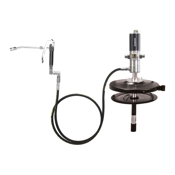
Fig.1
Grease Control Valve
Air Motor Assembly
Drum Cover
Z Swivel
Nozzle Holder
Cover Screws
High Pressure Rubber Hose
Follower Plate
Suction Tube
1
Advertisement
Table of Contents

Related Manuals for Groz GP1


Summary of Contents for Groz GP1
- Page 1 INSTRUCTION MANUAL S1230, Rev D Air Operated Grease Ratio Pumps 50:1 GP1, GP2, GP3 Congratulations on purchase of this World Class Air Operated Grease Ratio Pump ! • World-class Industrial High Pressure Grease pump with guaranteed performance & hassle free operation • Pump dispenses Grease at pressures upto 50 times the Air inlet pressure...
-
Page 2: Table Of Contents
Contents Page No. PUMP CONSTITUENTS ....................PUMP CONSTRUCTION ....................WORKING OF PUMP ..................... INSTALLATION ....................... PUMP OPERATION ......................MAINTENANCE & REPAIR ..................... 7-11 • Pumping Section Kit Replacement ................• Drive Section Kit Replacement................. 9-11 EXPLODED VIEW ......................PARTS LIST ........................13-14 TROUBLESHOOTING ...................... -
Page 3: Pump Constituents
PUMP CONSTITUENTS Fig. 2 Grease Pump Assembly Drum Cover with Thumb Screws Rubber Lined Follower Plate High pressure Rubber Hose Professional Grease Control Valve with Z Swivel PUMP CONSTRUCTION Fig. 3 The pump is made up of two sections as given below :- • Drive section :- It consists of an Air Motor Assembly driven by compressed air. -
Page 4: Working Of Pump
WORKING OF PUMP UPSTROKE DOWNSTROKE Fig. 4 Fig. 5 UPSTROKE - DOWNSTROKE - When Grease Control Valve is opened, compressed air enters The incoming air is now led via passage E to the upper side at arrow A and passes through passage B to the underside of of Piston C, driving it and the Piston Rod D downwards. -
Page 5: Installation
INSTALLATION NOTE An FRL (Filter-Regulator-Lubricator) unit must be used in the Air supply, before it is connected to the pump. Set the regulator to 6 BAR (90 PSI) or any required inlet pressure, but never more than 150 PSI (10 BAR) or less than 30 PSI (2 BAR). Fill the drum with Tighten the drum cover Grease leaving empty... -
Page 6: Pump Operation
PUMP OPERATION Partially open the on/off air valve (It helps in creating initial vacuum when filling a totally dry pump). Pump will start operating automatically until it gets primed. Pump is said to be Primed when grease is available at the pump outlet, making the pump ready to use. Once primed, the air motor will stop. -
Page 7: Maintenance & Repair
MAINTENANCE & REPAIR (Refer to Exploded View - Page 12) Service Precautions • Before performing any service operation, always shut off the air supply and release the pressure of the medium, i.e. let the grease out so that the pressure decreases. When storing the pump assembly without the bucket, cover the Filter Tube (57) with Filter Cap (62). • Be careful not to damage any parts when dismantling. - Page 8 Tighten a 1/2” male Hold Filter Tube (57) in threaded pipe into the vice. Using two wrenches outlet port & unscrew (size 28 mm), hold Bottom Air Motor Assembly Coupler (54) & unscrew anticlockwise. Carefully Top Coupler (52). Remove remove Air Motor from Slide Bush (53).
-
Page 9: Drive Section Kit Replacement
Drive Section Kit Replacement (Refer to Table 6 - Page 18) Support Extension Hold Barrel (63) in a soft- Rod (46) on a V block jaw vice. Pull out Filter & insert a pin punch Cap (62) by hand. vertically into the hole of Connector (45). - Page 10 Remove Bend Pipe (1) 13. Unscrew both Pushers along with both Coupling (15) using wrench (size Nuts (2) & Sealing Rings 25 mm). (3). Unscrew Exhaust Valve (23) with an adjustable wrench. Unscrew both Bends (4) 14. Remove both Pushers using wrench (size 13 (15), Springs (17), Pusher mm).
- Page 11 22. Replace the Repair Kit (KIT/TP/RPG) as mentioned in Table 6 17. Remove Slider (30) with a - Page 18, by following the steps 1-21 in reverse order taking tweezer. care of the points below: • Ensure all mating surfaces are clean before reassembly.
-
Page 12: Exploded View
EXPLODED VIEW DRUM COVER, FOLLOWER PLATE, HOSE, Fig. 6 Fig. 7 PUMP ASSEMBLY Z SWIVEL & GREASE CONTROL VALVE KIT/TP/RP-G KIT/BTM/RP-G 25 27 Correct Fitment of Seals (39) Conical side of Seals (39) must face upwards Replace Component No. 51, 52, 53 & 55 as a SET Correct Fitment of Slide Bush (53) &... -
Page 13: Parts List
PARTS LIST PARTS LIST FOR PUMP ASSEMBLY Table 1 REF. NO. FROM EXPLODED VIEW DESCRIPTION QUANTITY Bend Pipe Coupling Nut Sealing Ring Bend Cylinder Cover O Ring BS141 Plunger Nut Rubber Plunger Plunger Rod Cylinder O Ring BS614 Rod Guide O Ring Housing Pusher... - Page 14 REF. NO. FROM EXPLODED VIEW DESCRIPTION QUANTITY Washer Connecting Rod Slotted Spring Pin Connector Extension Rod Steel Ball (7/32”) Non Return Spring Valve O ring (BS812) Pump Cylinder Top Coupler Slide Bush Bottom Coupler Piston Rod Guide Bush Filter Tube Filter Washer Filter Circlip Piston Washer...
-
Page 15: Troubleshooting
TROUBLESHOOTING Table 3 (Refer to Maintenance & Repair - Page 7) PROBLEM POSSIBLE CAUSE SOLUTION Grease is too thick / too cold Store grease in a warm place Shake the Grease bucket & manually force down the Air pockets in grease Follower Plate (64) to remove air pockets Pump operates, but does not dispense any grease... -
Page 16: Replacement & Service Parts Program For Grease Ratio Pump
Table 4 (Refer to Exploded View - Page 12) REPLACEMENT PARTS PROGRAM REF. NO. FROM PART NO. DESCRIPTION QUANTITY EXPLODED VIEW FLP/241-288/6 GP1 Follower Plate FLP/322-380/6 GP2 Follower Plate FLP/550-602/6/GP3 GP3 Follower Plate DC/GP1/BL GP1 Drum Cover DC/GP2/BL GP2 Drum Cover... -
Page 17: Service Parts Program (Pumping Section Kit - Kit/Btm/Rp-G)
SERVICE PARTS PROGRAM (Pumping Section Kit - KIT/BTM/RP-G) Nyloc Nut Fig. 8 NN/M6/RP-G Steel Ball (7/32”) Piston Washer SB/7-32 WSR/PST/RP-G Non Return Spring SPR/NR/RP-G O Ring ORG/BS812 Pump Cylinder Slide Bush Fig. 9 Rod & Cylinder Assembly CYL/RP-G BSH/SLD/RP-G ROD/CYL/RP-G Component 51 52 53 must be replaced TOGETHER... -
Page 18: Service Parts Program (Drive Section Kit - Kit/Tp/Rp-G)
SERVICE PARTS PROGRAM (Drive Section Kit - KIT/TP/RP-G) Fig. 11 Fig. 12 Bend Seal Paper Seal SEL/R/RP BEND/90/RP SEAL/RP Sealing Ring Seat Nylon Slider Connecting Rod SR/B/RP SET/RP SLD/NY/RP ROD/CNR/S/RP Replace Component No. 24, 25 & 27 as a SET Slotted Spring Pin SSP/3/0.6/15.3 Slider Guide... -
Page 19: Specifications
SPECIFICATIONS Table 7 MODEL Bucket Capacity 20-30 Kg / 5 Gal / 25-50 lbs. 50-60 Kg / 16 Gal / 120 lbs. 180 Kg / 55 Gal / 400 lbs. Suction Tube Length 17.32” (440 mm) 28.74” (730 mm) 37.38” (950 mm) Suction Tube Dia. - Page 20 Village Kherki Daula, National Highway-8 Gurgaon-122001, Haryana, INDIA TEL +91.124.282.7700 / 221.4050 FAX +91.124.2827986 / 221.4224 FAX (USA) +1.509.271.7848 FAX (UK) +44.870.121.1854 E-MAIL info@groz-tools.com www.groz-tools.com The Groz name, Groz logo and the mark are trademarks of Groz Engineering Tools (P) Ltd. India...
Need help?
Do you have a question about the GP1 and is the answer not in the manual?
Questions and answers