Table of Contents
Advertisement
Quick Links
Advertisement
Table of Contents

Related Manuals for NIVELCO UNICONT PMG-400


Summary of Contents for NIVELCO UNICONT PMG-400
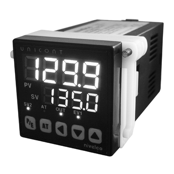
- Page 1 UNICONT PMG-400 Universal controller and display unit USER'S AND PROGRAMMING MANUAL edition Manufacturer: NIVELCO Process Control Co. H-1043 Budapest, Dugonics u. 11. Tel.: 889-0100 Fax: 889-0200 E-mail: sales@nivelco.com www.nivelco.com pmg4111a0600p_01 1 / 24...
-
Page 2: Table Of Contents
TABLE OF CONTENTS 1. GENERAL DESCRIPTION ........................3 2. ORDER CODE ............................3 3. TECHNICAL DATA..........................4 3.1 D ............................4 IMENSIONS 3.2 A ........................... 4 CCESSORIES 4. MOUNTING............................5 5. WIRING ..............................5 5.1 I ..........................5 NPUT SELECTION 5.2 W .................... -
Page 3: General Description
Thank you for choosing a NIVELCO instrument. We are sure that you will be satisfied throughout its use! 1. GENERAL DESCRIPTION The UNICONT PMG-411, PMG-412 and PMG-413 universal analogue PID-controllers can be used for temperature measurement with a Pt-100 resistance thermometer or different thermocouples. The UNICONT controllers are also suitable for processing and display the signals of field transmitters with 4-20 mA and 1-5 V DC or 0-10 V DC output. -
Page 4: Technical Data
3. TECHNICAL DATA Type PMG-41-1 Resistance thermometer Pt 100 (–199.9 °C...+199.9 °C or 0 °C...+500 °C) (3-wire, aut. cable R cable: max. 5 Ω compensation) K (-100 °C … +1100°C); J (0°C … +800°C) Thermocouple Input R (0°C … +1700°C); E (0°C …... -
Page 5: Mounting
4. MOUNTING OUNTING BRACKET The unit can be mounted with the help of the supplied mounting bracket to the suitable cut- out hole. Be careful with the sealing, which provides proper sealing from the front panel. Suitable distances between multiple units should be taken into consideration. -
Page 6: Wiring Power Supply , Input / Output
5.2 W IRING OWER UPPLY NPUT UTPUT PMG-411 PMG-412 WIRING WIRING – – – Pt100 Pt100 Relay output and Alarm output SSR driver output and Alarm output PMG-413 WIRING ARKINGS Power supply Control output – – Alarm output 4…20 mA Sensor input Pt100 Control input... -
Page 7: Control Outputs
6. CONTROL OUTPUTS 6.1 R ELAY OUTPUT The primary function of the relay output is the realization of the PID control. In case of PID control the relay output discontinuously turns off or on the load, thereby implements the PID control. ... -
Page 8: Solid State
6.2 S (SSR) OLID TATE ELAY DRIVER OUTPUT Using the SSR driver (voltage-impulse) output the unit is suitable for high-speed controlling tasks where the standard relay switching speed is not sufficient. SSR driver output is suitable for driving solid state relay with 12 V DC voltage and max.30 mA load. ... -
Page 9: Analogue (4-20 Ma) Output
6.3 A (4-20 mA) NALOGUE OUTPUT Using of the analogue output intervening devices with current input can be controlled. As an advantageous feature for example control valve with position control can be controlled using the analogue output. The control output of the unit provides the current value specified by the PID parameters. The 4 mA current value is assigned to 0 % and 20 mA is assigned to 100 %. -
Page 10: Settings, Programming
7. SETTINGS, PROGRAMMING 7.1 F RONT PANEL EYPAD ISPLAY In normal (measurement) mode the 7-segment displays show measured Process Value and the Set Value. In the other modes it shows texts values accordance to the actual state of the programming and configuration. With the 3 arrow ( , , ) buttons the menu-system can be handled... -
Page 11: Basic Operation
7.2 B ASIC OPERATION Enter the Set Value (SV) Normal (measurement) mode Setting the control Mode parameters Settings Note: The controller returns automatically from configuration mode, to normal (measurement) mode if there is no key activity for 60 seconds. 7.3 E RROR MESSAGES If any error occurs during the operation of the controller the display shows the following error messages: ... -
Page 12: Configuration Mode
7.5 C ONFIGURATION 7.5.1 M ETTINGS Normal (measurement) mode Mode settings ROGRAMMING EQUENCE Select the input from 19 options Select alarm relay mode Select alarm output mode Select auto-tuning mode Select PID control algorithm ... -
Page 13: Control Parameters
7.5.2 C ONTROL ARAMETERS Normal (measurement) mode Setting the control parameters ROGRAMMABLE ONTROL ARAMETERS Select SV-2 (internal set value) within input range for each sensor. SV-2 is effective if the IN input is active. Set alarm relay operation value (if alarm relay mode is selected in ... -
Page 14: Control Algorithms
To change the control parameters, press the button and hold for 3 seconds in normal (measurement) mode. If the configuration is completed press the button and hold for 3 seconds to return to normal (measurement) mode. , , , , , , , , parameters will be displayed only if the corresponding options are selected at the operating modes. -
Page 15: Proportional
8.3 P ROPORTIONAL CONTROL In case of proportional control the value of the Proportional band ( ) is not zero but the Integral time ( and the Derivative time ( ) are set to zero. The Proportional band can be set within the range of 1 to 100%. ... -
Page 16: In- And Output Mode Settings
9. IN- OUTPUT MODE SETTINGS 9.1 S ELECT THE NPUT MODE NPUT ISPLAY EASUREMENT RANGE K thermocouple K(CA)H . -100 °C … +1300 °C K thermocouple K(CA)L . -100 °C … +999.9 °C J(IC)H . J thermocouple 0 °C … +800 °C J(IC)L .... -
Page 17: Analogue Input
9.1.1 A NALOGUE INPUT When using analogue input the UNICONT controller could be connected to a 4-20 mA output level transmitter device for example. Scaling: In case of temperature measurement if the input is Pt100 or thermocouple, the device automatically determines the measurement range and the position of the decimal point according to the selected type of the input signal. -
Page 18: Alarm Relay Output
9.2 A LARM ELAY OUTPUT LARM VENTS Loop break alarm, see the details: chapter 9.3 Sensor break alarm, see the details: chapter 9.4 No alarm output Deviation High limit alarm The output will be ON when the Process Value (PV) ... -
Page 19: Loop Break Alarm (Lba)
LARM ELAY PTION ETTINGS Symbol Operation Description General alarm No optional alarm output, no latching Once the alarm output turns ON, it will be continuously Latch function activated. It can be turned OFF by selecting The alarm output will not turn ON the first time when PV reaches SV. -
Page 20: Sensor Break Alarm (Sba)
9.4 S (SBA) ENSOR REAK LARM When (Sensor Break Alarm) relay mode is used the alarm output indicates when sensor line is cut or open. This can be indicated for example by connecting a buzzer or an emergency light to the alarm output. ... -
Page 21: Ual Pid Control Function
9.6 D PID C ONTROL FUNCTION When controlling temperature there are two different options of PID control characteristics available. The first option is mode when the controller attempts to minimize the time until the Process Value (PV) ... -
Page 22: Ramp Function
9.7 RAMP FUNCTION The RAMP function allows setting delay for the rising or falling time of the temperature. When the Set Value (SV) is changed in case of heating the temperature will change in accordance to the rising time selected in parameter, in case of cooling the temperature will change in accordance to the falling ... -
Page 23: Setting The Control Parameters
10. SETTING THE CONTROL PARAMETERS 10.1 SV-2 FUNCTION NTERNAL ALUE There is a possibility to apply a second (internal) Set Value, using the parameter at the control parameters menu, which will be effective by external relay contact signal connected to the IN control input. -
Page 24: Factory Default Settings
-25 ... +60°C Relative humidity: max. 98 % 14. WARRANTY NIVELCO provides warranty of 3 (three) years in compliance with details described in the Warranty Card. pmg4111a0600p_01 2015. May NIVELCO reserves the right to change technical data without notice! ...
Need help?
Do you have a question about the UNICONT PMG-400 and is the answer not in the manual?
Questions and answers