Table of Contents
Advertisement
Advertisement
Table of Contents

Summary of Contents for Elcomed SA-310
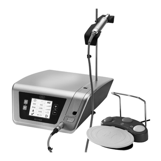
- Page 1 Instructions for use SA-310...
-
Page 2: Table Of Contents
9. Description of motor with cable ................................21 10. Starting operation – General ................................22 11. Switch on / switch off Elcomed ................................23 12. Control unit operation – Setup settings .............................. 24 13. Control unit operation – General settings ............................25 14. - Page 3 Contents 20. Technical data ......................................63 21. Disposal ........................................65 Explanation of warranty terms ..................................71 Authorized W&H service partners ................................72...
-
Page 4: Symbols
W&H Symbols Symbols in the Instructions for use WARNING! ATTENTION! General explanations, (risk of injury) (to prevent damage occurring) without risk to persons or objects Thermo washer disinfectable Sterilizable W&H Service up to the stated temperature... - Page 5 W&H Symbols Symbols on the control unit Follow instructions for use Do not dispose of Catalogue number with domestic waste Consult instructions for use Foot switch Serial number Class II equipment On / Off Supply voltage of the control unit Date of manufacture Electric fuse Alternating current...
- Page 6 W&H Symbols Symbols on the packaging This way up Temperature limits Caution: Federal law restricts this device to sale by or on the order of a dentist, physician or any other practitioner licensed by the law of the state in which he or she Fragile, handle with care Humidity limitation practices to use or order the use...
- Page 7 W&H Symbols Symbols on the irrigation tubing set Sterilized using ethylene oxide Consult instructions for use Caution: Federal law restricts this device to sale by or on the order of a dentist, physician or any other practitioner licensed by the law Do not reuse CE 0481 of the state in which he or she...
-
Page 8: Introduction
Qualifications of the user The W&H Elcomed dental surgical unit is intended for use by suitably qualified and trained medical, technical and specialist staff only. We have based our development and design of the Elcomed on the »physician« target group. - Page 9 > The Elcomed must be used in accordance with these Instructions for use. > The Elcomed has no components that can be repaired by the user. Assembly, modifications or repairs must only be undertaken by an authorized W&H service partner (see page 72).
-
Page 10: Electromagnetic Compatibility (Emc)
2. Electromagnetic compatibility (EMC) Notes on electromagnetic compatibility (EMC) Medical electrical equipment is subject to particular precautions with regards to EMC and must be installed and put into operation in accordance with the EMC notes included. W&H guarantees the compliance of the device with the EMC requirements only when used with original W&H accessories and spare parts. -
Page 11: Unpacking
3. Unpacking Lift out the insert with the Remove the carton with stand and the foot control. motor, accessories and instruments (optional). W&H packaging is environmentally friendly and can be Lift out the insert with the disposed of by industrial recycling companies. control unit. -
Page 12: Scope Of Delivery
4. Scope of delivery REF 15933100 Control unit with documentation REF 15933101 Control unit with documentation REF 05513400 Motor with 1.8 m cable REF 06205800 Motor with 3.5 m cable incl. 5 clips incl. 10 clips REF 436360 Irrigation tubing set 2.2 m REF 436410 Irrigation tubing set 3.8 m (3 pcs, disposable) -
Page 13: Safety Notes
> Before using the Elcomed for the first time, store it at room temperature for 24 hours. > Check the Elcomed, the straight or contra-angle handpiece and the motor with cable for damage and loose parts each time before using. Correct any faults or refer to an authorized W&H service partner (see page 72). Do not operate the Elcomed if it is damaged. - Page 14 Elcomed is not suitable for use in oxygen enriched atmospheres. Zone M is defined as a »medical environment« and constitutes the part of a room in which potentially explosive atmospheres may form due to the use of anaesthetics or medical antiseptics and antibacterial soaps;...
- Page 15 The power switch can also be used to safely stop the device. Power failure In the event of a power failure, if the Elcomed is switched off, or when switching between programs, the last values set are saved and re-activated when switching the device on again.
- Page 16 Intermittent operating mode S3 (2min/10min) The Elcomed is designed for intermittent operating mode S3 with an operating time of 2 minutes and an idle time of 10 minutes. If the operating mode specified is observed no overheating of the system and therefore no injury to the patients, users or third parties arises.
- Page 17 Safety notes Risks due to electromagnetic fields The functionality of implantable systems, such as cardiac pacemakers and ICD (implantable cardioverter defibrillator) can be affected by electric, magnetic and electromagnetic fields. > Find out if patient and user have implanted systems before using the product and consider the application. >...
-
Page 18: Description Of Front Panel
6. Description of front panel Pump arm Stand holder Display Shift buttons Pump arm OPEN PLUS / MINUS buttons Motor connecting socket... -
Page 19: Description Of Rear Panel
7. Description of rear panel USB connecting socket (only for REF 15933100 / REF 15933101) Stand holder Connecting socket for foot control Power switch ON / OFF Power socket Fuse holder with 2 fuses REF 06352200 (250 V – T1,6AH) -
Page 20: Description Of Foot Control
8. Description of foot control Handle ORANGE Change program attach / detach Programs 1 to 6 GREEN Pump ON / OFF YELLOW Change motor direction Clockwise / anticlockwise rotation GREY Start motor (pedal) VARIABLE or ON / OFF (Factory setting = variable) -
Page 21: Description Of Motor With Cable
9. Description of motor with cable The motor with cable must not be disassembled. The motor with cable must not be oiled (lubricated for life). To prevent the instrument on the motor attachment from turning during transmission of high torques, the locking pin supplied can be pushed into the designated hole (see illustration). -
Page 22: Starting Operation - General
10. Starting operation – General Always place the Elcomed on a flat level surface. Ensure that the Elcomed can be disconnected easily from the power supply. Connect the mains cable and Attach the motor support the foot control. -
Page 23: Switch On / Switch Off Elcomed
11. Switch on / switch off Elcomed Switch on Elcomed Switch off Elcomed Connect the Elcomed to the Turn the Elcomed off at the power supply. power switch. Turn the Elcomed on at the Disconnect the Elcomed from power switch. -
Page 24: Control Unit Operation - Setup Settings
For a description of the Elcomed settings see pages 32 – 37 Press the MINUS button to move from the setup settings to the main menu. Ensure when switching on the Elcomed that the LED display of the buttons and the display itself fully lights up. -
Page 25: Control Unit Operation - General Settings
13. Control unit operation – General settings Press shift button s or t to select the desired menu. Press the PLUS / MINUS button to set the menu functions. The selected functions light up in green. Date Date settings Time Time settings Contrast Contrast display... - Page 26 General settings – Date Date Activate date settings Select the day, month or year, or exit the date settings Adjust settings for day, month or year...
- Page 27 General settings – Time The clock stops while the settings are being adjusted. Time Activate time settings Select time format (am, pm, 24h), select hours, minutes or seconds or exit the time settings Adjust the settings for time format, hours, minutes, seconds...
- Page 28 General settings – Contrast Contrast Increase contrast Decrease contrast...
- Page 29 General settings – Volume Volume Increase volume Decrease volume Mute...
- Page 30 General settings – Reset factory settings The device will restart after the factory settings have been reset. Reset Start reset countdown The reset countdown can be interrupted within 5 seconds...
- Page 31 General settings – Factory settings (P1 – P6) Speed (rpm) 35,000 1,200 40,000 Torque (Ncm) 100 % 100 % 100 % 100 % Coolant supply volume 100 % 100 % 100 % 100 % 60 % 100 % Coolant active active active active...
-
Page 32: Control Unit Operation - Elcomed Settings
Programs (P1 – P6), Documentation Documentation setting Programs (P1 – P6), Thread cutter function Thread cutter setting Foot control Variable or On / Off Return To exit the Elcomed settings, select Return with shift button t. Confirm with the PLUS / MINUS button. - Page 33 Elcomed settings – Documentation (only for REF 15933100 / REF 15933101) Documentation On / Off The documentation for each program must be activated or deactivated. The On / Off documentation applies to both directions of rotation. Insert a USB flash drive to save the documentation.
- Page 34 Elcomed settings – Documentation Documentation is only possible at a preselected speed ≤50 rpm and only with transmission settings 975, WS-75 and WI-75. Speed, torque and coolant can be changed during documentation. Recording starts after a minimum torque of 1 Ncm is reached and ends 10 seconds after the motor is switched off.
- Page 35 Elcomed settings – Documentation Description Solution Symbol Documentation active Documentation not active Adjust W&H contra-angle handpiece, connect USB flash Documentation not possible drive, replace faulty USB flash drive, connect USB flash drive with sufficient memory space Connect USB flash drive,...
- Page 36 Elcomed settings – Thread cutter function (chip breaker mode) Activating the thread cutter function is only possible with transmission settings WS-75 and WI-75. When the thread cutter function is activated, the speed in both clockwise and anticlockwise rotations is 20 rpm and can no longer be changed.
- Page 37 Elcomed settings – Foot control To change from VARIABLE to ON / OFF Switching between variable and On / Off is only possible in this menu. Foot control Select setting = VARIABLE (factory setting) Continuously variable motor control...
-
Page 38: Control Unit Operation - Main Menu Settings
15. Control unit operation – Main menu settings Press shift button s or t to select the desired menu. Press the PLUS / MINUS button to set the menu functions. The selected functions light up in green. Programs (P1 – P6) Documentation On / Off Speed Speed display... - Page 39 Main menu settings – Changing the program Program Next program Previous program...
- Page 40 Main menu settings – Changing the speed When the safety speed (40,000 rpm) is reached, an audible signal (safety stop) sounds. To exceed the safety speed press the PLUS button once again or hold the PLUS button down (repeat function). Keeping PLUS / MINUS depressed activates the repeat function and the values are continuously increased / decreased.
- Page 41 Main menu settings – Changing the torque Settings range from 10 % to 100 % or 5 Ncm to 80 Ncm. Keeping PLUS / MINUS depressed activates the repeat function and the values are continuously increased / decreased. When the set torque in clockwise or anticlockwise rotation is reached, the motor automatically switches off. ...
- Page 42 Main menu settings – Changing the coolant flow Adjustable range: 0 % – 100 %. By keeping PLUS / MINUS depressed the values are continuously increased / decreased. Coolant Increase flow rate in 20 % steps Decrease flow rate in 20 % steps...
- Page 43 Main menu settings – Changing the transmission ratio Keeping PLUS / MINUS depressed activates the repeat function and the values are continuously increased / decreased. The transmission ratio can be adjusted only in clockwise rotation. Transmission ratio Select next transmission ratio ...
-
Page 44: Foot Control Operation
16. Foot control operation Changing the program > Press the ORANGE button to select programs 1 to 6 in ascending order. > Hold the ORANGE button down to select programs 6 to 1 in descending order. With each program change, the motor direction is automatically set to clockwise rotation. Pump ON / OFF Only when the motor is stationary can the pump be switched on or off by operating the GREEN button of the foot control. -
Page 45: Error Messages
17. Error messages Description Solution Error Foot control not recognized Connect foot control Connect a functioning foot control or Foot control error release the engaged button on the foot control Motor not recognized Connect motor Motor error Connect a functioning motor Motor faulty Connect a functioning motor Shift buttons or PLUS / MINUS buttons activated... - Page 46 If the error message appears again, contact an authorized W&H service partner. If one of the error messages described above cannot be rectified by switching off Elcomed and then switching it on again, the device must be checked by an authorized W&H service partner (see page 72).
-
Page 47: Hygiene And Maintenance
18. Hygiene and maintenance General notes Follow your local and national laws, directives, standards and guidelines for cleaning, disinfectionand sterilization. > Wear protective clothing, safety glasses, face mask and gloves. > Use only oil-free, filtered compressed air with a maximum operating pressure of 3 bar for manual drying. Cleaning agents and disinfectants >... - Page 48 Hygiene and maintenance Limitations on processing The product lifetime and the medical device’s ability to operate correctly are mainly determined by mechanical stress during use and chemical influences due to processing. > Send worn or damaged medical devices and/or medical devices with material changes to an authorized W&H service partner.
- Page 49 Hygiene and maintenance Initial treatment at the point of use > Clean and disinfect the medical device immediately after every treatment. > Wipe the control unit, the motor with cable, the motor support and the stand with disinfectant. Note that the disinfectant used during pre-treatment is only for personal protection and cannot replace the disinfectant step after cleaning.
- Page 50 Hygiene and maintenance Manual cleaning Motor with cable / Motor support / Stand > Do not immerse the motor with cable, the motor support or the stand in liquid disinfectant or in an ultrasonic bath. Motor with cable / Motor support / Stand >...
- Page 51 Hygiene and maintenance Manual disinfection Motor with cable / Motor support / Stand > W&H recommends wiping down with disinfectant. Evidence of the basic suitability of the motor with cable, the motor support and the stand for effective manual disinfection was provided by an independent test laboratory using the »mikrozid®...
- Page 52 Hygiene and maintenance Automated cleaning and disinfection Motor with cable / Motor support / Stand W&H recommends automated cleaning and disinfection using a washer-disinfector (WD). Read the notes, follow the instructions and heed the warnings provided by the manufacturers of washer-disinfectors, cleaning agents and/or disinfectants.
- Page 53 Hygiene and maintenance Drying Motor with cable / Motor support / Stand > Ensure that the motor with cable, the motor support and the stand are completely dry internally and externally after cleaning and disinfection. > Remove any liquid residues using compressed air.
- Page 54 Hygiene and maintenance Inspection, maintenance and testing Inspection – Motor with cable / Motor support / Stand > Check the motor with cable, the motor support and the stand after cleaning and disinfection for damage, visible residual soiling and surface changes. >...
- Page 55 Hygiene and maintenance Packaging Motor with cable / Motor support Pack the motor with cable and the motor support in sterilization packages that meet the following requirements: > The sterilization package must meet the applicable standards in respect of quality and use and must besuitable for the sterilization method.
- Page 56 Hygiene and maintenance Sterilization Motor with cable / Motor support W&H recommends sterilization according to EN 13060, EN 285 or ANSI/AAMI ST79. > Read the notes, follow the instructions and heed the warnings provided by the manufacturers of steam sterilizers. >...
- Page 57 Hygiene and maintenance Storage Motor with cable / Motor support > Store sterile goods dust-free and dry. > The shelf life of the sterile goods depends on the storage conditions and type of packaging.
-
Page 58: Servicing
18. Servicing Regular checks Regular servicing of function and safety including the accessories is necessary and should be carried out at least once every three years, unless shorter intervals are prescribed by law. The inspection must be undertaken by a qualified organization and must include the following procedures: Control unit >... - Page 59 Servicing Repairs and returns In the event of operating malfunctions immediately contact an authorized W&H service partner. Repairs and maintenance work must only be undertaken by an authorized W&H service partner. > Ensure that the medical device has been completely processed before returning it. >...
-
Page 60: W&H Accessories
Use only original W&H accessories / spare parts 19. W&H Accessories or accessories approved by W&H 06177800 04005900 06290600 Motor support Stand Clips (5 pcs) 05513400 04006800 06352200 Motor with 1.8 m cable Locking pin Fuse (250 V – T1.6AH) incl. - Page 61 W&H Accessories 07945930 04013500 06290700 Transportation case Sterilization cassette USB flash drive 06202400 04653500 Foot control S-N1 Handle for foot control S-N1...
- Page 62 W&H Accessories Disposable item 04363600 04719400 Irrigation tubing set 2.2 m (6 pcs) Irrigation tubing set 2.2 m 04364100 Irrigation tubing set 3.8 m (6 pcs)
-
Page 63: Technical Data
20. Technical data Elcomed SA-310 Supply voltage: 110 – 130 V / 220 – 240 V Permitted voltage fluctuation: ±10 % Nominal current: 0.1 – 1.8 A / 0.1 – 0.9 A Mains fuse: 2 x 250 V – T1.6AH Frequency: 50 –... - Page 64 Technical data Classification according to Paragraph 5 of the General Specifications for the Safety of Medical Electrical Equipment according to IEC 60601-1 / ANSI/AAMI ES 60601-1 Class II medical electrical equipment (protective earth conductor used for functional earth connection only!) Type BF applied part (not suitable for intracardiac application) The foot control REF 06202400 conforms to class AP according to IEC 60601-1 / ANSI/AAMI ES 60601-1 in danger zone M...
-
Page 65: Disposal
21. Disposal Ensure that the parts are not contaminated on disposal. Follow your local and country-specific laws, directives, standards and guidelines for disposal. > Medical device > Waste electrical equipment > Packaging... - Page 67 W&H course certificate for the user The user has been trained to use the medical device correctly in accordance with the legal regulations (medical devices marketing regulations, medical devices act). Particular attention has been paid to the chapters on safety notes, start-up, operation, hygiene and maintenance, and service (regular inspections). Product name Serial number (SN) Manufacturer with address...
- Page 69 W&H course certificate for the instructor The user has been trained to use the medical device correctly in accordance with the legal regulations (medical devices marketing regulations, medical devices act). Particular attention has been paid to the chapters on safety notes, start-up, operation, hygiene and maintenance, and service (regular inspections). Product name Serial number (SN) Manufacturer with address...
-
Page 71: Explanation Of Warranty Terms
Ex p lana ti on o f warra nty te rms This W&H product has been manufactured with great care by highly qualified specialists. A wide variety of tests and controls guarantee faultless operation. Please note that claims under warranty can only be validated when all the directions in the Instructions for use have been followed. -
Page 72: Authorized W&H Service Partners
Authorized W&H service partners Find your nearest W&H service partner at http://wh.com Simply go to the menu option »Service« for full details. Alternatively please contact: W&H (UK) LIMITED, Unit 6, Stroud Wood Business Centre, Park Street, St Albans, Hertfordshire AL2 2NJ, United Kingdom t + 44 1727 874990, f + 44 1727 872254, E-Mail: technical.uk@wh.com W&H Impex Inc., 6490 Hawthorne Drive, Windsor, Ontario, N8T 1J9, Canada t + 1 800 2656277, 1 519 9446739, f + 1 519 9746121, E-Mail: service.ca@wh.com... - Page 74 Manufacturer W&H Dentalwerk Bürmoos GmbH Ignaz-Glaser-Straße 53, 5111 Bürmoos, Austria Form-Nr. 50668 AEN t + 43 6274 6236-0, f + 43 6274 6236-55 Rev. 011 / 13.03.2019 office@wh.com wh.com Subject to alterations...
Need help?
Do you have a question about the SA-310 and is the answer not in the manual?
Questions and answers