HPE 3PAR StoreServ 9000 Customer Self Install Manual
Hide thumbs
Also See for 3PAR StoreServ 9000:
- Software user's manual (73 pages) ,
- Service and upgrade manual (147 pages) ,
- Service and upgrade manual (174 pages)
Table of Contents
Advertisement
HPE 3PAR StoreServ 9000 Storage
Customer Self Install Guide
Abstract
This document provides information and instructions to guide you through the installation of
your HPE 3PAR StoreServ 9000 Storage system without the assistance of an authorized
service provider. If installation assistance is needed, contact your HPE sales representative or
HPE Channel Partner to purchase the HPE Deployment Services.
Part Number: QL226-99978a
Published: January 2019
Edition: 4
Advertisement
Table of Contents

Related Manuals for HPE 3PAR StoreServ 9000


Summary of Contents for HPE 3PAR StoreServ 9000
- Page 1 Abstract This document provides information and instructions to guide you through the installation of your HPE 3PAR StoreServ 9000 Storage system without the assistance of an authorized service provider. If installation assistance is needed, contact your HPE sales representative or HPE Channel Partner to purchase the HPE Deployment Services.
- Page 2 HPE InfoSight content Q0E92-90703 February 2018 With HPE 3PAR OS 3.3.1 (MU1) Patch 09, Patch 11, and Patch 18 software, also known as HPE 3PAR OS 3.3.1 EMU1, and HPE 3PAR Service Processor 5.0.2.1 software or later software...
-
Page 3: Table Of Contents
Contents Guidelines for the Customer Self Install of the HPE 3PAR StoreServ 9000..................6 About the HPE 3PAR StoreServ 9000 Storage system......8 Installation media.......................... 9 Serial number location........................9 Forum for the storage system....................... 9 Preparing: Process overview...............10 Site planning..........................10 Customer Self Install videos......................11... - Page 4 About the HPE InfoSight platform..................50 Creating an account to access the HPE InfoSight web portal..........50 Registering the storage system with the HPE InfoSight web portal using the HPE 3PAR StoreServ Management Console................51 Adding workstations to the public firewall rules................52 Configuring the host and SAN: Process overview..............
- Page 5 Alerts issued by the storage system and processed by the service processor......89 Browser warning when connecting to the service processor............89 Checking the system health, HPE 3PAR Service Processor 5.x software, Service Console interface............................93 Failed installation of a virtual service processor with Hyper-V............93 Identifying drive enclosure (cage) numbering in the software.............93...
-
Page 6: Guidelines For The Customer Self Install Of The Hpe 3Par Storeserv 9000
The storage system is shipped in the HPE Rack, ready for installation at the customer site. • The CSI of the HPE 3PAR StoreServ 9000 must be performed using the HPE 3PAR Guided Setup that is a feature of the HPE 3PAR OS 3.3.1. CSI installer technical profile:... - Page 7 Partner to purchase HPE Deployment Services CSI installer responsibilities: • Review all the relevant documentation for the HPE 3PAR StoreServ 9000 prior to initiating the installation. • Ensure that the host and SAN environment is supported and compliant with HPE recommendations and best practices.
-
Page 8: About The Hpe 3Par Storeserv 9000 Storage System
The SP only sends support data to HPE 3PAR Remote Support. The HPE 3PAR virtual SP is deployed as a virtual machine (VM) and runs on a customer-owned, customer-provided server and communicates with the storage system over its Ethernet connection. -
Page 9: Installation Media
An HPE Passport profile and a valid Service Agreement ID (SAID) are required to access downloads. Serial number location The HPE 3PAR StoreServ 9000 Storage system has a 10-character serial number that is used with the software setup. The storage system serial number can be found in these locations: •... -
Page 10: Preparing: Process Overview
2. Review Regulatory information on page 100. 3. Review Customer Self Install videos on page 11. 4. Complete the HPE 3PAR StoreServ 9000 Storage Software Set up Worksheet on page 95. 5. Review Acclimatizing on page 11. 6. Obtain the Tools for the installation on page 11. -
Page 11: Customer Self Install Videos
HPE 3PAR StoreServ 9000 Storage Site Planning Manual available at the Hewlett Packard Enterprise Information Library website: www.hpe.com/info/storage/docs Customer Self Install videos The HPE 3PAR StoreServ 9000 Storage Customer Self Install (CSI) videos are available at the HPE 3PAR StoreServ 9000 Storage Customer Self Install Video website: www.hpe.com/support/3PAR9000CSIVideo NOTE: The video may take a minute to load. -
Page 12: Unpacking The Factory-Integrated-In-Rack Option: Process Overview
During this procedure, refer to the unpacking diagrams on the outside of the cardboard shipping container. For more information about placement of the HPE 3PAR StoreServ Storage system and reserving room for service access, see the HPE 3PAR StoreServ 9000 Storage Site Planning Manual available at the Hewlett Packard Enterprise Information Library website: www.hpe.com/info/storage/docs NOTE: The illustrations in this procedure are examples and might not be an exact representation of your HPE rack (cabinet). - Page 13 Figure 2: Items for unpacking an HPE rack 1. Rack (cabinet) 2. Ramps 3. Caster guides 4. Ramp supports 5. Pallet Unpacking the factory-integrated-in-rack option: Process overview...
- Page 14 • When the equipment arrives, verify that there is enough space to unload and unpack the HPE 3PAR StoreServ Storage system. The specific amount of space for unpacking the storage system is based on the dimensions of the container, ramp, and room. This space is required to access the storage system so that it can be removed from the crate and moved to its final location.
- Page 15 Figure 4: Removing the top, HPE rack shipping container 3. Remove the clips along the corrugated fiber board (CFB) walls and separate the CFB walls. Place the separated walls away from the storage system. Figure 5: Removing the clips, HPE rack shipping container...
- Page 16 4. Remove the packing material (wrapping material, foam pieces, plastic ESD cover), and then set aside the boxes that hold the ramps and additional installation hardware. Figure 6: Removing the packing material, HPE rack shipping container 5. Remove the four shipping L-brackets that attach the rack to the pallet using a socket wrench with 13 mm (1/2 in) and 17 mm (11/16 in) sockets.
- Page 17 Figure 7: Releasing the locking nut, HPE rack leveling bolt b. With an adjustable wrench, turn the leveling bolt counterclockwise until fully raised. Figure 8: Raising the leveling bolt, HPE rack 7. Close and secure the rack front and rear doors.
- Page 18 Figure 10: Installing the ramps onto the pallet, HPE rack shipping container Unpacking the factory-integrated-in-rack option: Process overview...
- Page 19 The wooden ramp supports must fit snugly between the ramp and the floor. Figure 11: Installing the ramp supports, HPE rack shipping container 9. Roll the rack from the pallet to the floor.
-
Page 20: Positioning And Stabilizing The Hpe Rack
Obtain an adjustable wrench for leveling the feet on the HPE rack. Procedure 1. Roll the HPE rack to the final operating location. If the operating location has raised floor tiles with cutouts to facilitate cable routing, position the rack over the cutouts in the tiles. -
Page 21: Installing The Drives: Process Overview
Figure 13: Lowering an HPE rack leveling bolt c. Lock the leveling pad in place by turning the locking nut counterclockwise until tight. Figure 14: Tightening the locking nut on an HPE rack leveling bolt d. Repeat for each leveling pad. -
Page 22: Guidelines For The Drive Installation
Procedure 1. Review Guidelines for the drive installation on page 22. 2. Complete Installing the SFF drives on page 23. Guidelines for the drive installation IMPORTANT: The guidelines for how the drives are installed, allocated, and balanced are critical to the performance and reliability of your storage system. -
Page 23: Installing The Sff Drives
Table 2: Example slot order, SFF drive enclosure 20 (...) 21 (...) 22 (...) 23 (...) 24 (Do not use) 15 (...) 16 (...) 17 (...) 18 (...) 19 (...) 10 (...) 11 (...) 12 (...) 13 (...) 14 (...) 5 (SSD) 6 (SSD) 7 (SSD) -
Page 24: Cabling The Factory-Integrated-In-Rack Option: Process Overview
For an HPE 3PAR StoreServ 9000 Storage system that is factory integrated in an HPE rack, the internal cabling for the data cables and power cables has been completed before shipment; however, you must... - Page 25 Cable type Minimum bend radius Network Cat 5/6 (Unshielded) 1.75 in (4.44 cm) Network Cat 5/6 (Shielded) 3.5 in (8.90 cm) Coaxial (50W) 1.2 in (3 cm) Coaxial (75W) 1.7 in (4.31 cm) R1 InfiniBand - at connector 4.6 in (11.68 cm) R2 InfiniBand - away from connector 2.6 in (6.60 cm) •...
-
Page 26: Guidelines For Redundant Power Cabling
• Restrain and support cables in a manner that eliminates stress on connectors and eliminates tight bends of the cables. • Secure fiber and AOC cables with loose fitting Velcro straps, instead of wire or cable ties. • For cable ties, ensure that the cables are not compressed when cinching the tie, and cut the cable ties flush with the cable tie head to prevent scratches or cuts during future service interactions. -
Page 27: Cabling The Physical Service Processor (If Installed)
Figure 16: Redundant power configuration Cabling the physical service processor (if installed) The physical service processor is an optional component that can be used with the HPE 3PAR StoreServ 9000 Storage system instead of using a virtual service processor. IMPORTANT: Do not turn on power to the components at this time. Connect the power cables and keep the power off until you power on the components. -
Page 28: Cabling The Controller Nodes: Process Overview
Figure 18: Physical service processor ports, HPE ProLiant DL360 Gen10 Server Management (MGMT) port; NIC 1 Service port; NIC 2 2. Connect and secure the cable for the power connection. Power connection—Connect a power cable to a power source, but do not turn on the power yet. -
Page 29: Cabling For The Host Connection
Cabling for the host connection Prerequisites Before connecting any FC or iSCSI cables, follow the guidelines provided for your host OS that are available in an HPE 3PAR host-OS implementation guide available at the Hewlett Packard Enterprise Information Library website: www.hpe.com/info/storage/docs For instance, the following are some of the available HPE 3PAR host-OS implementation guides: •... - Page 30 ◦ For an FC switch, you must set up FC fabric zoning to restrict WWNs seen by the system. NOTE: With HPE 3PAR File Persona or HPE 3PAR Remote Copy, an additional Ethernet connection is required. See “Supported Network Topologies” in the HPE 3PAR StoreServ 9000 Storage Site Planning Manual available at the Hewlett Packard Enterprise Information Library website: www.hpe.com/info/storage/docs...
-
Page 31: Cabling For The Remote Copy Connection (Optional Feature)
Cabling for the Remote Copy connection (optional feature) Hewlett Packard Enterprise For the optional HPE 3PAR Remote Copy connection with the HPE 3PAR StoreServ 9000 Storage, see the HPE 3PAR Remote Copy Software User Guide available at the Hewlett Packard Enterprise Information Library website: www.hpe.com/info/storage/docs... -
Page 32: Cabling The Power Cords Of The Power Distribution Units To The Power Receptacles At The Operating Site
Procedure Connect a cable between a port on a two-port 10Gb Ethernet NIC adapter and the network. To provide redundancy, connect two or more controller nodes per storage system. Cabling the power cords of the power distribution units to the power receptacles at the operating site IMPORTANT: Do not turn on power to the components at this time. -
Page 33: Powering On: Process Overview
• To avoid potential damage to equipment, do not adjust the positioning of the rack after powering on the HPE 3PAR StoreServ Storage. Checking AC power cable connections A factory-integrated storage system arrives with all internal power cables configured and connected. -
Page 34: Powering On The Storage System
• The storage system does not exceed the ratings of the power sources and adheres to the guidelines in the HPE 3PAR StoreServ 9000 Storage Site Planning Manual available at the Hewlett Packard Enterprise Information Library website: www.hpe.com/info/storage/docs •... -
Page 35: Checking Enclosure Power Redundancy (Optional)
IMPORTANT: The Status LED at the storage system front is not illuminated green at this time. Instead, after the power on sequence, the UID/Service LED is illuminated blue and the Fault LED is illuminated amber. Later during the software Guided Setup, these LEDs turn off and the Status LED becomes illuminated green. - Page 36 Procedure 1. Ensure that all power supplies (power supply units) for the enclosures (controller node enclosure and drive enclosure) have a solid-green status LED indicating a normal operation state. • Review Power supply unit LEDs, controller node enclosure on page 82 . •...
-
Page 37: Setting Up The Service Processor Connection: Process Overview
SP and the virtual SP provide remote monitoring and report storage system errors, and can perform diagnostic and maintenance activities involving the storage system. With HPE 3PAR SP 5.x software, only one standalone HPE 3PAR StoreServ 9000 Storage system can be added to the service processor. -
Page 38: Network And Firewall Support Access
SP and access to the HPE 3PAR CLI of an attached storage system. The intent of the HPE 3PAR TUI is not to duplicate the functionality of the HPE 3PAR SP Service Console interface, but to allow a way to fix problems that may prevent you from using the Service Console interface. - Page 39 ◦ https://storage-support.glb.itcs.hpe.com (16.248.72.63) ◦ https://storage-support2.itcs.hpe.com (16.250.72.82) • HPE Remote Support Connectivity Global Access Servers: ◦ https://c4t18808.itcs.hpe.com (16.249.3.18) ◦ https://c4t18809.itcs.hpe.com (16.249.3.14) ◦ https://c9t18806.itcs.hpe.com (16.251.3.82) ◦ https://c9t18807.itcs.hpe.com (16.251.4.224) • HP Remote Support Connectivity Global Access Servers: ◦ https://g4t2481g.houston.hp.com (15.201.200.205) ◦ https://g4t2482g.houston.hp.com (15.201.200.206) ◦...
-
Page 40: Setting Up The Physical Service Processor Connection: Process Overview
The physical service processor (SP) and the HPE 3PAR StoreServ Storage are connected to a network with a gateway. • The service processor must be on the same subnet as the HPE 3PAR StoreServ Storage system. Procedure 1. Connect a service laptop to the physical service processor. - Page 41 IP Address: 10.255.155.49 Subnet mask: 255.255.255.248 3. To begin the HPE 3PAR Guided Setup, access the service processor from the service laptop: a. In a browser window, enter: https://10.255.155.54:8443/ b. Read the HPE End-User License Agreement and then click Accept.
-
Page 42: Setting Up The Virtual Service Processor Connection With Vmware Esxi: Process Overview
Setting up the virtual service processor connection with VMware ESXi: Process overview Prerequisites • Verify that you have the virtual service processor (SP) installation software on either a DVD or from an email that was sent with a link to download the software, which might have gone to the email account responsible for purchasing the storage system. -
Page 43: Locating Or Assigning An Ip Address To The Virtual Service Processor With Vmware Esxi
Procedure Start the VMware vSphere Client, and then select the IP address of the vSphere server from the IP address/Name list. Enter the user name and password, and then click Login. On the File menu, click Deploy OVF Template. The Deploy OVF Wizard opens. Enter or select the OVF file that you want to deploy, and then click Open. -
Page 44: Setting Up The Virtual Service Processor Connection With Hyper-V: Process Overview
From the Software Setup Worksheet, enter the default gateway address and press Enter. To configure the network, enter Y. The full URL that you will need for accessing the SP is displayed. For example, https:// <sp_ip_address>:8443. To return to the main menu, press X. 10. -
Page 45: Assigning An Ip Address To The Virtual Service Processor With Hyper-V
5. Enter the netmask address and then press Enter. 6. Enter the default gateway address and then press Enter. 7. Review the configuration confirmation and record the service processor IP address on to the HPE 3PAR StoreServ 9000 Storage Software Setup Worksheet for reference during subsequent setup procedures with the software HPE 3PAR Guided Setup. -
Page 46: Setting Up The Service Processor And Storage System Software: Process Overview
Hewlett Packard Enterprise Information Library website: www.hpe.com/info/storage/docs The storage system is configured with the help of the HPE 3PAR Guided Setup. By completing the HPE 3PAR Guided Setup, the storage system will be operational. To set up the software for the service processor and the storage system, complete the following process: Procedure 1. -
Page 47: Setting Up The Service Processor Using The Hpe 3Par Guided Setup
Guided Setup Procedure 1. To access the HPE 3PAR Guided Setup, connect to the service processor (SP) through a browser with the SP IP address: https://<sp_ip_address>:8443/. IMPORTANT: If you receive a warning from your browser when you enter the SP URL, see Browser warning when connecting to the service processor on page 89. -
Page 48: Setting Up The Storage System Using The Hpe 3Par Guided Setup
Setting up the storage system using the HPE 3PAR Guided Setup Procedure 1. Once the service processor (SP) has restarted after setting up the service processor using the HPE 3PAR Guided Setup, the Service Console login page is displayed with a single button and the Guided Setup window open. -
Page 49: Installing And Setting Up The Hpe 3Par Storeserv Management Console Software: Process Overview
Help for setting up and managing your HPE 3PAR StoreServ Storage system. The HPE 3PAR SSMC Online Help is available from the Help window from any location within the Main Console. To open the Help window, click the question mark (?) in the upper right corner of the dashboard window. -
Page 50: Post-Installation Tasks
Systems that are registered with HPE InfoSight must be added to a system group, and then users in the organization can be added to the system group. Typically, a single system group is all that is necessary to manage multiple systems through the process of assigning users and setting their roles and permissions for the system group. -
Page 51: Registering The Storage System With The Hpe Infosight Web Portal Using The Hpe 3Par Storeserv Management Console
This token is text beginning with StoreFrontRemoteAccess and will be pasted into a Token field in the Main Console interface. 6. From the server on which the HPE 3PAR SSMC software is installed, access the Main Console: a. Browse to https://<IP address or FQDN>:8443. -
Page 52: Adding Workstations To The Public Firewall Rules
TIP: The default port number is 8443. Another port might have been assigned during installation of the software. The login screen opens. b. Enter a user name and password, make sure the check box for Administrator Console is clear, and then click Login. The Dashboard screen is displayed. -
Page 53: Configuring The Host And San: Process Overview
Complete Configuring a host using a host-OS implementation guide on page 53. • Only for HPE 3PAR Smart SAN, see the HPE 3PAR Smart SAN User Guide available at the Hewlett Packard Enterprise Information Library website: www.hpe.com/info/storage/docs. Configuring a host using a host-OS implementation guide... -
Page 54: Validating The Hpe 3Par Remote Support Connectivity To Hpe 3Par Central
Hewlett Packard Enterprise strongly recommends configuring HPE 3PAR Remote Support connectivity (also known as the Call Home feature) to HPE 3PAR Central when installing your HPE 3PAR StoreServ Storage system. The remote support connection is set during the software HPE 3PAR Guided Setup. If needed, remote support connectivity can be tested using the HPE 3PAR Service Processor (SP) software Service Console interface, which might need to be checked after making any network changes. - Page 55 2016-08-29 11:14:01 PDT Created 2016-08-29 11:14:01 PDT Start user operation 2016-08-29 11:14:04 PDT SP localhost test passed. 2016-08-29 11:14:07 PDT SP public interface test passed. 2016-08-29 11:14:10 PDT SP gateway test passed. 2016-08-29 11:14:10 PDT Policy Server connectivity test skipped: policy server not configured.
-
Page 56: More Information
NOTE: • The illustrations of components are examples only and might not accurately represent the configuration of your HPE 3PAR StoreServ Storage system. • Due to the large number of prospective configurations, component placement and internal cabling is standardized to simplify installation and maintenance. The components are numbered according to their order and location in the rack. -
Page 57: Controller Node Information
(0) and increments in ascending order from bottom to top. Figure 25: Controller node numbering, controller node enclosure rear view Table 4: Controller node loading order Storage system Number of controller nodes Loading order HPE 3PAR StoreServ 0, 1 9450 Storage 0, 1, 2, 3 More information... -
Page 58: Controller Node Internal Components Information
1. Power switch 2. 10 GbE port (RCIP) 3. 1 GbE Management (MGMT) port 4. Service port (Console) Figure 26: Power switch and onboard ports, controller node rear view Controller node internal components information Figure 27: Internal components of the controller node More information... -
Page 59: Drive Enclosure Information
Item Component DIMM Location (Slot ID) Description Control cache DIMMs J18000 CC DIMM 0:0:0 J19000 CC DIMM 0:1:0 J20000 CC DIMM 0:2:0 Control cache DIMMs J18001 CC DIMM 1:0:0 J19001 CC DIMM 1:1:0 J20001 CC DIMM 1:2:0 Data cache DIMMs Bank 0:0 J14005 DC DIMM 0:0:0 J15005... - Page 60 1. Left bezel ear cap 2. SFF drive bays 3. Right bezel ear cap Figure 28: SFF drive enclosure details front view Pullout tab with serial number Fan module 0 I/O module 1 I/O module ejector handle I/O module 0 SAS data ports Fan module 1 System-locate UID/push button...
-
Page 61: Drive Information
NOTE: The drive enclosure contains 25 SFF drive bays (slots); however, do not use the upper-right bay (slot 24). Figure 30: SFF drive bay numbering, drive enclosure front view Drive information • Drive type: Solid state drives (SSDs) only • Drive size: 2.5 inch small form factor (SFF) SSD •... -
Page 62: Fan Module Information, Drive Enclosure
Fan module information, drive enclosure Figure 32: Fan module numbering, drive enclosure rear view I/O module information Figure 33: I/O module numbering, drive enclosure rear view Power supply unit information, controller node enclosure There are two power supply units (PSUs) for each controller node. The following illustration displays the numbering sequence of the PSUs. -
Page 63: Power Supply Unit Information, Drive Enclosure
12 drive enclosures are supported in the base rack. • With the storage system installed in a 42U 1,200 mm HPE rack, vertical PDUs are used and up to 16 drive enclosures are supported in the base rack. -
Page 64: Rack Information
Rack information The HPE 3PAR StoreServ 9000 Storage system comes installed in either a 42U, 1,075 mm, or 1,200 mm HPE rack or as individually packaged components for installation in a customer-supplied rack. When multiple racks are in use, the racks are configured as follows: •... -
Page 65: Physical Service Processor Information, Hpe Proliant Dl360 Gen10 Server
Figure 37: HPE ProLiant DL120 Gen9 Server details NOTE: For the HPE ProLiant DL120 Gen9 Server, the NIC port 2 is configured for shared mode to either be configured for use as the Service port or configured for use as an iLO (virtual serial) port. -
Page 66: System Information Front View (Typical Component Configuration)
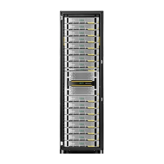
2. Service port; NIC 2 Figure 39: HPE ProLiant DL360 Gen10 Server details For the HPE ProLiant DL360 Gen10 Server, the Service port, iLO Management port, and Serial port are dedicated ports NOTE: The ports are different than the HPE ProLiant DL120 Gen9 Server. - Page 67 1. Physical service processor (SP) 2. Power distribution units (PDUs) 3. Controller node enclosure 4. Backup battery units (BBUs) 5. Fan modules 6. Drive enclosures 7. Leveling bolt Figure 40: 1,075 mm HPE Rack front view More information...
-
Page 68: Component Leds
Figure 41: 1,200 mm HPE Rack front view Component LEDs IMPORTANT: The HPE 3PAR StoreServ Storage system components have LEDs to indicate whether the hardware is functioning properly and to help identify errors. The LEDs help diagnose basic hardware problems. -
Page 69: Nvme Scm Module Leds
NVMe SCM Module LEDs Figure 42: HPE 3PAR 750GB NVMe Storage Class Memory Module LEDs Table 6: HPE 3PAR 750GB NVMe Storage Class Memory Module LEDs Function Status Port state UID/Service Blue solid Locate active; safe to remove Blue flashing Locate active;... -
Page 70: Two-Port 32 Gb Fc Hba Leds
Two-port 32 Gb FC HBA LEDs Figure 43: HPE 3PAR Two-Port 32Gb FC Host Bus Adapter LEDs Table 7: HPE 3PAR Two-Port 32Gb FC Host Bus Adapter LEDs Function Status Port state Link/Status Green solid Normal/connected; link up Green flashing... -
Page 71: Two-Port 10 Gb Iscsi Cna Leds
3. Link LED 4. Fault LED 5. Status LED 6. UID/Service LED Figure 44: HPE 3PAR Two-Port 10Gb iSCSI Converged Network Adapter LEDs Table 8: HPE 3PAR Two-Port 10Gb iSCSI Converged Network Adapter LEDs Ethernet LED Activity LED Link LED... -
Page 72: Two-Port 10 Gb Ethernet Nic Adapter Leds
Table 9: HPE 3PAR Two-Port 10Gb iSCSI Converged Network Adapter LEDs LED Function Status Indicates Fault Amber Solid Fault Status Green Solid Normal operation; no fault UID/Service Blue Solid Locate active; safe to remove Blue Flashing Locate active; do not remove component... -
Page 73: Four-Port 16 Gb Fc Hba Leds
Locate active and/or safe to remove Blue flashing Locate active; do not remove component Four-port 16 Gb FC HBA LEDs Figure 46: HPE 3PAR Four-Port 16Gb FC Host Bus Adapter LEDs Table 11: HPE 3PAR Four-Port 16Gb FC Host Bus Adapter LEDs Function Status... -
Page 74: Four-Port 12 Gb Sas Hba Leds
Four-port 12 Gb SAS HBA LEDs Figure 47: HPE 3PAR Four-Port 12Gb SAS Host Bus Adapter LEDs Table 12: HPE 3PAR Four-Port 12Gb SAS Host Bus Adapter LEDs Function Status Port state Port speed Amber solid Not connected Connected Link status Green solid Normal/connected;... -
Page 75: Backup Battery Unit Leds
Backup battery unit LEDs Figure 48: Backup battery unit LEDs Table 13: Backup battery unit LEDs Function Status State UID/ Blue solid Locate active and/or safe to remove Service Blue flashing Locate active; do not remove component Status Green solid Battery functioning Fault Amber solid... -
Page 76: Controller Node Leds And Ports
Controller node LEDs and ports Figure 49: Controller node LEDs and ports, controller node enclosure rear view Fault LED Status LED UID/Service LED 10 GbE SFP port (RCIP) - optical SFP/connector Link activity LED Speed LED 1 GbE MGMT port (management) - standard CAT-5/RJ-45 connector Link activity LED - Activity/Link Speed LED - Speed 10. -
Page 77: Drive Enclosure Leds
Callout LED Status State 10 GbE port Link down 10 GbE port: Green solid Link up Link activity LED Green flashing Link activity 100 MB or none 10 GbE port: Green solid 1 GB Speed LED Amber solid 10 GB MGMT port Link down MGMT port:... -
Page 78: Drive Leds
Figure 51: Drive enclosure LEDs, rear view Table 16: Drive enclosure LEDs, rear view LED function Display State Locate UID TIP: This UID push button activates or deactivates the Blue UID LED on the rear and front of the Drive Enclosure. Blue solid Location activated Status... -
Page 79: Fan Module Leds
Function Status State Amber Noncritical fault flashing No power Fan module LEDs Fan module LEDs, controller node enclosure Figure 53: Fan module LEDs, controller node enclosure front view Table 18: Fan module LEDs, controller node enclosure front view Function Status State UID/Service Blue solid Locate active and/or safe to remove... -
Page 80: Fan Module Leds, Drive Enclosure
Fan module LEDs, drive enclosure Figure 54: Fan module LEDs, drive enclosure rear view Table 19: Fan module LEDs, drive enclosure rear view LED function Status State Locate UID Blue solid Locate activate; safe to remove Blue flashing Locate activate ; do not remove component Status Green solid Normal operation... - Page 81 Table 20: I/O modules LEDs, drive enclosure rear view LED function Display State Health/Fault Green solid Normal operation Amber solid Fault UID/Service Blue solid Location requested; safe to remove Blue flashing Location requested; do not remove Indicates maintenance in progress; for example, firmware updating Figure 56: SAS port LEDs, drive enclosure rear view LED Function...
-
Page 82: Power Supply Unit Leds
LED Function Status State Fault Amber solid • With solid green Activity LED, link at low speed with no activity. • With flashing green Activity LED, link at low speed with activity. • With green Activity LED off, no link or no cable connected. Amber flashing With flashing green Activity LED, locate requested. -
Page 83: Power Supply Unit Leds, Drive Enclosure
Green solid Normal operation Amber flashing Non-critical fault Amber solid Critical fault No power Service processor LEDs Physical service processor LEDs, HPE ProLiant DL120 Gen9 Server Figure 59: Physical service processor LEDs, HPE ProLiant DL120 Gen9 Server rear view More information... - Page 84 Power supply failure • Power supply in standby mode • Power supply error Figure 60: Physical service processor LEDs, HPE ProLiant DL120 Gen9 Server front view Table 24: Physical service processor LEDs, HPE ProLiant DL120 Gen9 Server front view LED/Port function Status...
-
Page 85: Physical Service Processor Leds, Hpe Proliant Dl360 Gen10 Server
Physical service processor LEDs, HPE ProLiant DL360 Gen10 Server Figure 61: Physical service processor LEDs, HPE ProLiant DL360 Gen10 Server rear view Table 25: Physical service processor LEDs, HPE ProLiant DL360 Gen10 Server rear view... - Page 86 One or more of the following conditions exists: • AC power unavailable • Power supply failed • Power supply in standby mode • Power supply exceeded current limit. Figure 62: Physical service processor LEDs, HPE ProLiant DL360 Gen10 Server front view More information...
-
Page 87: System Status Leds-Controller Node Enclosure
*When all four LEDs described in this table flash simultaneously, a power fault has occurred. System status LEDs—controller node enclosure The HPE 3PAR StoreServ 9000 Storage system status LEDs are at the front, right corner of the controller node enclosure. - Page 88 Table 27: System status LEDs, controller node enclosure front view Function Status State UID/Service Blue solid Locate active Status Green solid Normal operation; no fault Fault Amber solid Fault More information...
-
Page 89: Troubleshooting
Alerts are triggered by events that require intervention by the system administrator. To learn more about alerts, see the HPE 3PAR Alerts Reference: Customer Edition and HPE 3PAR StoreServ Storage Concepts Guide documents available at the Hewlett Packard Enterprise Information Library website or the Hewlett Packard Enterprise Support Center website: www.hpe.com/info/storage/docs... - Page 90 Solution 2 Cause Warning message in Google Chrome browser. Action 1. Click the Advanced link. 2. Click Proceed to <sp_ip_address> (unsafe). Troubleshooting...
- Page 91 Solution 3 Cause Warning message in Mozilla Firefox browser. Action 1. Click Advanced. 2. Click Add Exception..Troubleshooting...
- Page 92 3. (Optional) To remove the warning for this site in the future, select Permanently store this exception in the Add Security Exception dialog. 4. In the Add Security Exception dialog, click Confirm Security Exception. Troubleshooting...
-
Page 93: Checking The System Health, Hpe 3Par Service Processor 5.X Software, Service Console Interface
Checking the system health, HPE 3PAR Service Processor 5.x software, Service Console interface Procedure 1. Connect and log in to the HPE 3PAR Service Processor (SP) 5.x software, Service Console interface. a. Browse to the IP address https://<sp_ip_address>:8443/. b. Enter the account credentials, and then click Login. - Page 94 Action Identification of a drive enclosure in the rack: 1. Connect and log in to the HPE 3PAR Service Processor (SP). a. Browse to the IP address https://<sp_ip_address>:8443/. b. Enter the account credentials, and then click Login. 2. Open the Service Console main menu by clicking 3PAR StoreServ Service Console in the upper-left corner.
-
Page 95: Hpe 3Par Storeserv 9000 Storage Software Set Up Worksheet
To prepare for the software setup using the HPE 3PAR Guided Setup software, complete this worksheet. Information is needed for the HPE 3PAR Service Processor, the HPE 3PAR StoreServ 9000 Storage system, and the HPE 3PAR StoreServ Management Console (SSMC). - Page 96 Email Phone To locate the serial number, see the HPE 3PAR StoreServ Storage documentation. The password is restricted to 31 characters in length and can contain alphanumeric characters and the following special characters: plus (+), dash (-), underscore (_), asterisk (*), and “at” symbol (@).
-
Page 97: Websites
Websites Hewlett Packard Enterprise general websites: Information Library www.hpe.com/info/EIL Customer Self Repair Services Media Library www.hpe.com/support/sml-csr InfoSight infosight.hpe.com Safety and Compliance www.hpe.com/support/Safety-Compliance-EnterpriseProducts Software Depot www.hpe.com/support/softwaredepot Software License Manager enterpriselicense.hpe.com/ Software updates and licensing www.hpe.com/downloads/software Support Center www.hpe.com/support/hpesc SPOCK www.hpe.com/storage/spock White papers and analyst reports www.hpe.com/storage/whitepapers... -
Page 98: Support And Other Resources
Support and other resources Accessing Hewlett Packard Enterprise Support • For live assistance, go to the Contact Hewlett Packard Enterprise Worldwide website: http://www.hpe.com/assistance • To access documentation and support services, go to the Hewlett Packard Enterprise Support Center website: http://www.hpe.com/support/hpesc Information to collect •... -
Page 99: Customer Self Repair
IMPORTANT: Access to some updates might require product entitlement when accessed through the Hewlett Packard Enterprise Support Center. You must have an HPE Passport set up with relevant entitlements. Customer self repair Hewlett Packard Enterprise customer self repair (CSR) programs allow you to repair your product. If a CSR part needs to be replaced, it will be shipped directly to you so that you can install it at your convenience. -
Page 100: Regulatory Information
Documentation Feedback (docsfeedback@hpe.com). When submitting your feedback, include the document title, part number, edition, and publication date located on the front cover of the document. For online help content, include the product name, product version, help edition, and publication date located on the legal notices page. -
Page 101: Acronyms
Acronyms one-unit rack space two-unit rack space four-unit rack space alternating current all flash array Battery Backup Unit Control Cache (DIMMs) confidential disclosure agreement command line interface converged network adapter Customer Self Install data at rest DHCP dynamic host configuration protocol domain name system electrostatic discharge Fibre Channel (protocol) or fast class (drive type) - Page 102 field replaceable unit Gigabyte Gb/s or Gbps Gigabits per second Gigabit Ethernet graphical user interface host bus adapter input/output integrated lights out I/O Module local area network logical unit number network interface card network time protocol OOTB out of the box open virtual format PCIe peripheral component interconnect express...
- Page 103 SFRM HPE StoreFront Remote Service Processor single power supply secure service agent solid state drive (drive type) Secure Shell SSMC HPE 3PAR StoreServ Management Console transmission control protocol TOTP time-based one-time password HPE 3PAR Text-based User Interface Acronyms...
- Page 104 unit of space in a rack unit identification virtual machine virtual volume watt Acronyms...
Need help?
Do you have a question about the 3PAR StoreServ 9000 and is the answer not in the manual?
Questions and answers