
Subscribe to Our Youtube Channel
Summary of Contents for SigTEL Compact
- Page 1 SigTEL Compact Emergency Voice Communication System (EVCS) Installation and Configuration Manual Approved Document No. DAU0000091 Rev 5...
-
Page 2: Table Of Contents
AN EXPLANTION OF TERMS AND DEFINITIONS USED IN THESE INSTRUCTIONS IS LISTED IN SECTION 21. Contents IMPORTANT NOTES ..............................4 REGULATIONS AFFECTING EVCS ........................... 4 SIGTEL COMPACT COMPONENTS ..........................5 MCU ( . ECU-4, ECU-8, ECU-16) ........................5 PART NOS LCU ( . - Page 3 SigTEL Compact Installation and Configuration Manual SECOND FIX INSTALLATION ............................19 13.1 C MCU/LCU ........................19 ONNECTING EXTENSIONS TO THE 13.2 F ..............................19 AULT MONITORING 13.3 I ..............................20 NPUT CONNECTIONS 13.4 O ..............................20 UTPUT CONNECTIONS MCU/LCU INDICATORS & CONTROLS ......................... 21 14.1 E...
-
Page 4: Important Notes
Do not run SELV and LV cables in the same enclosure without adequate insulation between them. SigTEL EVCS control equipment is designed to be installed indoors. Outstations are not IP rated so should not be installed outdoors unless an IP65, or better housing, is used and cables are installed so as to prevent the ingress of moisture. -
Page 5: Sigtel Compact Components
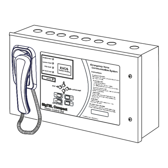
SigTEL Compact Installation and Configuration Manual 3 SigTEL Compact Components Note: See Specification (section 19) for component details. MCU (part nos. ECU-4, ECU-8, ECU-16) The master control unit (MCU) controls the EVCS and allows the MCU’s Operator to communicate with the outstations. -
Page 6: Typeb Disabled Refuge Outstation - Flush Mounted ( Part No . Evc302F/Gf)
SigTEL Compact Installation and Configuration Manual Type B Disabled Refuge Outstation - flush mount ed (part no. EVC302F/GF) Identical to the EVC302S/GS version but with a flat fascia suitable for flush installation. The EVC302F has a stainless steel fascia and the EVC302GF has a green mild steel fascia. An IP66 rated housing (BF359/1) is available to allow the outstation to be used outdoors. -
Page 7: Key Features Of The Evcs Networked System
SigTEL Compact Installation and Configuration Manual 3.11.1 Key features of the EVCS networked system: 1. Allows the interconnection of up to 14 MCUs or LCUs using 4 x 2-core, 1.5 mm , enhanced fire-rated wiring. 2. Maximum length on the speech wiring loop, or digital linear wiring = 1 km. -
Page 8: Typical Systems
SigTEL Compact Installation and Configuration Manual 5 Typical Systems System up to 4 extension s Equipment required (shown right) One MCU (ECU-4), requires two 12 volt 7 Ah batteries (BC286/2). One 3 A fused spur and back box. One Type A Outstation (EVC301RPO/EVC301RLK), or one Type B Outstation (EVC302F/GF/S/GS), or one DPTA (NC951) per extension. -
Page 9: System Up To 16 Extensions
SigTEL Compact Installation and Configuration Manual System up to 16 extension s Equipment required One MCU (ECU-16), requires two 12 volt 7 Ah batteries (BC286/2). One 3 A fused spur and back box. One Type A Outstation (EVC301RPO/RLK), or one Type B Outstation (EVC302F/GF/S/GS), or one DPTA (NC951) per extension. -
Page 10: Networked System Up To 224 Extensions
SigTEL Compact Installation and Configuration Manual Networked s ystem up to 224 extensions Equipment required Up to 14 MCU (ECU-16), requires two 12 volt 7 Ah batteries (BC286/2) per MCU. One 3 A fused spur and back box per MCU. -
Page 11: First Fix Installation
SigTEL Compact Installation and Configuration Manual 6 First Fix Installation Equipment location Control equipment Unless installed in an enclosure of at least IP65 rating, all equipment must be sited indoors and MUST NOT be subjected to conditions likely to affect its performance, such as damp, salt air, water, extreme temperatures, physical abuse, etc. -
Page 12: Mounting Enclosures
SigTEL Compact Installation and Configuration Manual 7 Mounting Enclosures The MCU/LCU is supplied in a steel back-box with a hinged steel lid and several printed circuit boards (PCBs), as shown below. MCU Hinged Lid MCU Back Box Control PCB Master Exchange PCB Power Supply PCB The MCU/LCU can be surface, or semi-flush mounted (maximum depth 60 mm including dimples). -
Page 13: Fix The Base To The Wall
SigTEL Compact Installation and Configuration Manual Fix the base to the wall Using the four mounting holes, fix the base securely to the wall using suitable screw fixings. The mounting holes are designed for No. 8 round-head, or countersunk wood-screws. Any dust, or swarf, must be kept out of the enclosure and great care must be taken not to damage the wiring or components. -
Page 14: Re-Install The Base Pcbs
SigTEL Compact Installation and Configuration Manual Re-install the base PCBs Re-install the base PCBs and refit the lid. Ensure the fixing screws and all interconnection cables are refitted correctly, as shown below. To Operator handset Cat 5 cables (supplied) Power... -
Page 15: Installing The Ecu722 Network Comms Card (Optional)
SigTEL Compact Installation and Configuration Manual 8 Installing the ECU722 Network Comms Card (Optional) The MCU/LCU has a Master Exchange PCB and Power Supply PCB mounted in its base unit and a lid-mounted Control PCB. The ECU722 card has to be mounted on top of the Master Exchange PCB. Before carrying out the steps below, ensure that Mains power is isolated and the MCU/LCU batteries are disconnected. -
Page 16: Network Connections (Optional)
SigTEL Compact Installation and Configuration Manual 9 Network Connections (Optional) The EVCS network allows up to 14 MCUs and LCUs to be connected by installing a Network Communications Card (ECU722) in each unit. The ECU722 card transmits speech audio via a single wiring loop and digital data via two linear RS485 networks (Digital Networks 1 &... -
Page 17: Mains Wiring
SigTEL Compact Installation and Configuration Manual 10 Mains Wiring Connect Mains to the MCU/LCU See BS 5839-9 section 13. MCU/LCU mains connections The MCU/LCU requires fixed wiring using 3-core enhanced fire-rated cable (no less than 0.75 mm and no more than 2.5 mm... -
Page 18: Fitting Outstations & Dpta Interface
SigTEL Compact Installation and Configuration Manual 11 Fitting Outstations & DPTA Interface 11.1 Cables See section 4. 11.2 Location See section 6.1. 11.3 Fitting type A outstation ( EVC301RPO/EVC301RLK To MCU Red + Black - Open the case and unscrew the fixing screw at the bottom of the unit and remove the internal cover (see far right). -
Page 19: Testing Extensions
Note: See Specification (section 19) for component details. Each extension should be tested prior to termination and connection to the Master Exchange PCBs. We recommend that a SigTEL FiTT line tester is used to save time proving the cables and outstations are working correctly. -
Page 20: Input Connections
SigTEL Compact Installation and Configuration Manual 13.3 Input connections I/P A I/P B I/P C 1. I/P A (Disable controls) – Disables Type A and Type B outstations. 2. I/P B (Disable controls) – Disables input signals from the DPTA. -
Page 21: Mcu/Lcu Indicators & Controls
SigTEL Compact Installation and Configuration Manual 14 MCU/LCU Indicators & Controls 14.1 External indic ators Indicator Colour What this means The EVCS is powered up and checking for faults but the MCU is disabled from making, or receiving calls, until an external trigger is applied, e.g. from a fire... -
Page 22: External Controls
SigTEL Compact Installation and Configuration Manual 14.3 External controls The MCU/LCU external control buttons are located on its keypad. They are multifunctional dependent on the unit’s current status. Note: The numbers 1, 2, 3, & 4 are used for entering security PIN codes using the keypad (by responsible persons only). -
Page 23: Powering Up And Testing
SigTEL Compact Installation and Configuration Manual Each fault display has two lines. The format depends on whether the fault relates to an extension or not. Format 1: Extension faults Format 2: Non-extension faults Line 1 - Extension name Line 1 - Fault description, e.g. Mains fail... -
Page 24: Automatic Configuration
SigTEL Compact Installation and Configuration Manual 17 Automatic Configuration E V C S If the fault menu is displayed, press END button to exit the menu. The backlight will go out and the display will 2 F a u l t s say ‘System Healthy’... -
Page 25: Networked Mcu/Lcu Configuration
SigTEL Compact Installation and Configuration Manual 17.2 Networked MCU/LCU configuration Note: If a single, non-networked MCU is being configured refer to section 17.1. Before configuring the network, ensure all MCU/LCU, outstations and DPTA interfaces have been installed, connected and tested. Ensure that all handsets are on-hook and toilet alarms are cleared and reset. - Page 26 SigTEL Compact Installation and Configuration Manual 6. After all repeater MCU/LCU have joined the network, the system will automatically perform an Auto Learn and detect the attached extensions. The Auto Learn system configuration is displayed at the master MCU, see example below right.
-
Page 27: Adding Or Replacing Mcu/Lcu, Outstations Or Dpta After Commissioning
SigTEL Compact Installation and Configuration Manual 17.3 Adding or re placing MCU/LCU, outstations or DPTA after commissioning Note: Compatibility issues may arise if adding/replacing a panel with the latest firmware onto a networked system with earlier firmware. Some features of the new firmware may be disabled/unavailable to ensure smooth compatibility with the panels with earlier firmware. -
Page 28: Interactive Naming
SigTEL Compact Installation and Configuration Manual 17.5.1 Interactive naming This function reduces the chance of errors with outstation locations and their names. It also tests that the audio is working acceptably. This function has limited use when naming toilet alarms as you cannot make an audio call to the MCU using the toilet alarm. -
Page 29: Additional Engineer Functions
SigTEL Compact Installation and Configuration Manual 18 Additional Engineer Functions 18.1 Change the security PIN code Note: For a networked system, this option can only be accessed at the master MCU. The default security PIN code 2222 1. Open the lid of the MCU and press the Engineer Mode button. The ‘Eng. Opts’ menu is displayed. -
Page 30: Latch Faults
SigTEL Compact Installation and Configuration Manual 18.3 Latch faults Note: For a networked system, this option can only be accessed at the master MCU. Latch Faults option is not normally enabled but is available, if required for fault diagnosis purposes, e.g. identifying intermittent faults. -
Page 31: Clear Recent Calls
SigTEL Compact Installation and Configuration Manual 18.4 Clear recent calls Note: For a networked system, this option can only be accessed at the master MCU. Clear Recent Calls enables the call activity log, held by the system, to be automatically cleared after a set time period. -
Page 32: Component Specifications
SigTEL Compact Installation and Configuration Manual 19 Component Specifications Note: This specification applies to MCUs (ECU-16, ECU-8, ECU-4) & LCU (ECU-8NT) unless stated. Power Supply and Batteries Mains supply 230 VAC, 50/60 Hz Power supply output 1 24 VDC Power supply output 2... - Page 33 SigTEL Compact Installation and Configuration Manual Dimensions & Weight (unpacked) 435 mm (w) x 270 mm (h) x 85 mm (d). Weight: 3.1 Kg Enclosure BF359/3D 725 mm (w) x 448 mm (h) x 193 mm (d). Weight 11.1 Kg Type A Outstation EVC301RPO/RLK 202 mm (w) x 278 mm (h) x 100 mm (d).
-
Page 34: Firmware Version
Installation and Configuration Manual Enhanced Features As the firmware for the SigTEL Compact range of panels has been developed, new enhanced features have been added. The enhanced features and corresponding firmware versions are listed in Table 1, below: Firmware Version V 4.1.2... -
Page 35: Installation And Commissioning Certificate
SigTEL Compact Installation and Configuration Manual 20 Installation and Commissioning Certificate Before the system and the Operator Instructions are handed over to the responsible person on site, the following certificate should be completed by the installer, or commissioning engineer. Certificate for the EVCS at:... -
Page 36: Terms And Definitions
SigTEL Compact Installation and Configuration Manual 21 Terms and Definitions For the purposes of these instructions the following terms and definitions apply: disabled persons toilet alarm (DPTA) interface DPTA interfacing is a secondary function to the primary purpose of the system which is to act as an EVCS. Toilet alarms can only be reset at the alarm point and cannot be reset by the EVCS.
Need help?
Do you have a question about the Compact and is the answer not in the manual?
Questions and answers