Table of Contents
Advertisement
Advertisement
Table of Contents

Summary of Contents for Tele Radio Tiger Shark
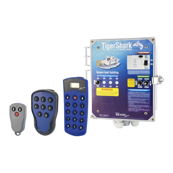
- Page 1 Manual and installation instructions Technology by:...
-
Page 2: Table Of Contents
TigerShark boat lift solutions Table of contents Getting started ..............3 Control panel ........................4 Raise/lower the boat using automatic systems ..............4 Raising/lowering the boat manually ..................5 Adjusting the boat hoist level ....................6 Raising/lowering the boat outside of the boat hoist’s stopping positions....7 Remote control ........................ -
Page 3: Getting Started
Getting started How to use the control panel and the remote control for the boat hoist Explanation of signs: = Quick press = Hold down/up... -
Page 4: Control Panel
TigerShark boat lift solutions OVERIDE BOAT UP Control panel Raise/lower the boat using automatic systems AUTO ON BOAT DOWN OVERIDE BOAT UP You can use the automatic systems to raise or lower the boat to a preset position OVERIDE BOAT UP by briefly pressing the boat up/down lever. -
Page 5: Raising/Lowering The Boat Manually
OVERIDE BOAT UP OVERIDE BOAT UP AUTO ON BOAT DOWN AUTO ON BOAT DOWN Raising/lowering the boat manually OVERIDE BOAT UP You can lower or raise the boat manually without using the automated stopping sys- OVERIDE BOAT UP tem. When the boat has been raised or lowered to its final position, the hoist turns off. -
Page 6: Adjusting The Boat Hoist Level
OVERIDE BOAT UP TigerShark boat lift solutions AUTO ON BOAT DOWN Adjusting the boat hoist level AUTO ON BOAT DOWN You can adjust the level of the hoist motors using the control panel. Do this by OVERIDE BOAT UP turning off one of the motors using the LEVEL breaker. This may be necessary if OVERIDE BOAT UP the boat hoist is on a slant or if a level adjustment must be performed for other... -
Page 7: Raising/Lowering The Boat Outside Of The Boat Hoist's Stopping Positions
Raising/lowering the boat outside of the boat hoist’s stopping positions. You can lower or raise the boat outside of the preset stopping positions for the boat hoist. This can be useful (i.e. at high or low tide), when the hoist doesn’t reach high or low enough. -
Page 8: Remote Control
TigerShark boat lift solutions Remote control Raising/lowering the boat using remote control You can automatically lower or raise the boat to a preset position by briefly pressing either the up or down button. The boat is lowered or raised to the position set as the end point during installation. - Page 9 Lowering the boat automatically: Press both arrow The LED turns buttons to turn transmitter power on. Pressing the down button lowers the boat hoist to the stop position.
-
Page 10: Other Remote Control Functions
TigerShark boat lift solutions Other remote control functions: The remote control can also be used to control other objects on or around the boat. The standard remote control supports the control of two different objects. You will find suggestions below. Your re seller can provide you with a transmitter that allows you to control several objects at once. -
Page 11: Installation
Installation the control panel How to install WARNING! This section of the manual is only for licensed electricians and installers. Interference with high-voltage equipment is illegal for individuals without the required training/authorization. WARNING WARNING Hazardrous voltage Hazardrous voltage Contact may cause Wrongful handling may cause electric shock or burn. -
Page 12: Limit Switch
TigerShark boat lift solutions Limit switch The limit switch is connected to the boat hoist motor. With the help of a micro- breaker, this unit senses how high or how low the boat hoist has been moved. When the boat hoist is in the top position, a high position breaker cuts the power to the motor. -
Page 13: Functional Description Of Limit Switch
Functional description of limit switch The limit switch, which connects to the engine axle, is turned when the engine axle is spinning, turning the breaker handle in turn. The breaker handle should be adjusted so that when the engine axle is spinning enough, (i.e. when the hoist is in the desired top or bottom position), the micro-breakers engage to cut the power to the motor. -
Page 14: Adjustment Of Limit Switch (Hoist)
TigerShark boat lift solutions Adjustment of limit switch (hoist) In order for the limit switch to work properly, it needs to be adjusted upon installation. This is done in two steps, first when the boat hoist is in the top position, and then when it is in the bottom position - this is when the breaker handles are adjusted. -
Page 15: Adjusting The Limit Switch (Lowering)
Adjusting the limit switch (lowering) In order for the limit switch to work properly, it needs to be adjusted upon installation. This is done in two steps, first when the boat hoist is in the top position, and then when it is in the bottom position - this is when the breaker handles are adjusted. -
Page 16: Connection Of Limit Switch To Control Panel
TigerShark boat lift solutions Connection of limit switch to control panel Below, you’ll see how the connections should be drawn from the micro-breakers’ poles to the connection console in the control panel. Connection box in control panel BLUE BLACK WARNING! It is very important that this phase of the installation is carefully thought out and performed with precision. -
Page 17: Installation
Installation How to install the limit switch WARNING! This section of the manual is only for licensed electricians and installers. Interference with high-voltage equipment is illegal for individuals without the required training/authorization. WARNING WARNING Hazardrous voltage Hazardrous voltage Contact may cause Wrongful handling may cause electric shock or burn. -
Page 18: Mounting The Limit Switch Into The Hoist Motor
TigerShark boat lift solutions Mounting the limit switch into the hoist motor The installation of the limit switch may vary depending on the type of boat hoist it is being installed on. Below are some examples. Limit switch Crankshaft Hoist motor In the image, the limit switch is mounted at a 90 degree angle to the crankshaft. - Page 19 Crankshaft Limit switch Crankshaft Limit switch...
- Page 20 TigerShark boat lift solutions Option 2 Limit switch Crankshaft...
- Page 21 Option 3 Limit switch Crankshaft...
- Page 22 TigerShark boat lift solutions Option 4 Limit switch...
- Page 23 Intentionally left blank...
-
Page 24: General Notice
TigerShark boat lift solutions General notice The TigerShark system is delivered in a 230V (2 phase 115V) version. The reason behind this is to minimize the following if the wrong installation is performed: • Possible transformer blowout • Possible contactor blowout •... -
Page 25: Installation
There are a number of different motor solutions on the market. We present the most COMMON ones here. NOTE: Your motor MAY NOT be pictured Read the instructions for your motor for the correct connection. Tele Radio cannot be held responsible for connections made OUTSIDE the TigerShark box. WARNING! This section of the... -
Page 26: Connecting Hoist Motors To The Control Panel
Tele Radio will not be responsible for improper connections. = Cap = Screw... - Page 27 230 V Add WHITE cable and wire together with Motor BLACK Wire together Motor ORANGE with Motor BLUE and TigerShark BLACK Wire together Motor WHITE with Motor BLUE and TigerShark BLACK NOTE: Do this change on both motors! 115 V...
-
Page 28: Standard T-Motor
Tele Radio will not be responsible for improper connections. Standard T-motor A.O. Smith, Baldor, Dayton, Deco, GE,... - Page 29 230 V Add WHITE cable and wire together with Motor T5 Wire together Motor T3 with Motor T1 and TigerShark BLACK Wire together Motor T2 with Motor T4 and TigerShark ORANGE NOTE: Do this change on both motors! 115 V...
-
Page 30: Eastbay Motor
Tele Radio will not be responsible for improper connections. Eastbay motor 230 V... - Page 31 230 V Add a WHITE cable between “N” and “B” Move TigerShark ORANGE cable from “C” to “D” Move TigerShark BLACK cable from “A” to “E” NOTE: Do this change on both motors! Remove the JUMPER WIRE Move TigerShark RED cable from “E”...
-
Page 32: Ao Smith Motor
Tele Radio will not be responsible for improper connections. AO Smith motor 230 V... - Page 33 230 V Add a WHITE cable to “N” and wire together with Motor BLACK Move BLUE jumper from “5” to “4” Move Motor BLACK and wire together with newly added WHITE cable NOTE: Do this change on Move Motor WHITE to position “1”...
-
Page 34: Leeson Balldor Motor
Tele Radio will not be responsible for improper connections. Leeson Balldor motor 230 V... - Page 35 230 V Add a WHITE cable to “N” and wire together with Motor T5 NOTE: Do this change on both motors! Wire together cable T3 with cable T1 and TigerShark BLACK Wire together cable T2 with cable T4 and TigerShark ORANGE 115 V...
-
Page 36: General Electric Motor
Tele Radio will not be responsible for improper connections. General Electric motor 230 V... - Page 37 230 V Add a WHITE cable to “N” and wire together with Motor RED Move and connect TigerShark BLACK to “1” and “5” NOTE: Do this change on both motors! Move Motor WHITE and wire together with Motor YELLOW and TigerShark ORANGE Move Motor RED cable and wire together with newly added TigerShark WHITE 115 V...
-
Page 38: Century Magnatech Motor
Tele Radio will not be responsible for improper connections. Century Magnatech motor 230 V... - Page 39 230 V Add a WHITE cable to “5” Move Motor ORANGE to “1” Move Motor WHITE to “6” NOTE: Do this change on both motors! 115 V...
-
Page 40: Emerson Motor
Tele Radio will not be responsible for improper connections. Emerson motor 230 V... - Page 41 230 V Add a WHITE cable to “4” Move Motor ORANGE to “3” Move Motor WHITE to “1” NOTE: Do this change on both motors! 115 V...
-
Page 42: Leeson Motor
Tele Radio will not be responsible for improper connections. Leeson motor 230 V... - Page 43 230 V Add a WHITE cable to “N” and “5” Move Motor BROWN to “2” Move Motor PURPLE to “1” NOTE: Do this change on both motors! 115 V...
-
Page 44: Baldor Motor
Tele Radio will not be responsible for improper connections. Baldor motor 230 V... - Page 45 230 V Add a WHITE cable to “N” wire together with Motor BLACK / T5 Move Motor WHITE / T2 to “L2” Move Motor Wire together with BROWN / J to “4” TigerShark WHITE NOTE: Do this change on both motors! 115 V...
-
Page 46: Appendix
TigerShark boat lift solutions Appendix Internal connection schematic and wiring charts Your TigerShark unit has been delivered how it appears on the following page (Delivery design). Before connecting power you must first determine what AC voltage your boat lift requires and then proceed to change the wiring accordingly. In the following pages you will find all the different voltages that can be available at your location. -
Page 47: Connection Schematics
Connection schematics Delivery design WARNING WARNING Hazardrous voltage Hazardrous voltage US 230 VAC Contact may cause Wrongful handling may cause electric shock or burn. electric shock or burn. (2 phase, 115 VAC) Can only be installed Disconnect power by licensed electrician. before servicing. - Page 48 TigerShark boat lift solutions Change instructions Delivery design, US 230 VAC -> US 115 VAC (1 phase, 115 VAC) Remove this conductor. Move the red and blue conductor bundle to the 230V connection box 115V labelled N on the lower row of the GFIC.
- Page 49 WARNING WARNING Connection schematic Hazardrous voltage Hazardrous voltage US 115 VAC Contact may cause Wrongful handling may cause electric shock or burn. electric shock or burn. Can only be installed Disconnect power (1 phase, 115 VAC) by licensed electrician. before servicing. 115V 230V INCOMING NEUTRAL (N)
- Page 50 TigerShark boat lift solutions Change instructions Delivery design US 230 VAC -> 3 phase, 115 VAC Move the red conductor from box 5 down to L2 on the terminal strip 230V 115V Disconnect the brown 230V Move the black conductor and isolate. Connect conductor from L2 the black 115V conductor to to L3.
- Page 51 WARNING WARNING Connection schematic Hazardrous voltage Hazardrous voltage 3 phase, 115 VAC Contact may cause Wrongful handling may cause electric shock or burn. electric shock or burn. Can only be installed Disconnect power by licensed electrician. before servicing. 230V ISOLATE 115V INCOMING NEUTRAL (N) INCOMING PHASE 1 (115VAC)
- Page 52 TigerShark boat lift solutions Change instructions Delivery design, US 230 VAC -> EU 230 VAC (1 phase, 230 VAC) Remove this conductor. Move the red and blue conductor bundle to the 230V 115V connection box labelled N on the lower row of the GFIC.
- Page 53 WARNING WARNING Connection schematic Hazardrous voltage Hazardrous voltage EU 230 VAC Contact may cause Wrongful handling may cause electric shock or burn. electric shock or burn. Can only be installed Disconnect power (1 phase, 230 VAC) by licensed electrician. before servicing. 230V 115V INCOMING NEUTRAL (N)
- Page 54 TigerShark boat lift solutions Change instructions Delivery design, US 230 VAC -> 380 VAC (3 phase, 380 VAC) Move the red conductor from box 5 down to L2 on the main box 230V 115V Move the black Move the brown 230V conductor from L2 conductor to box N on to L3.
- Page 55 WARNING WARNING Connection schematic Hazardrous voltage Hazardrous voltage 3 phase, 380 VAC Contact may cause Wrongful handling may cause electric shock or burn. electric shock or burn. Can only be installed Disconnect power by licensed electrician. before servicing. 115V ISOLATE 230V INCOMING NEUTRAL (N) INCOMING PHASE 1 (L1)
-
Page 56: Wire Size Recommendation Chart
TigerShark boat lift solutions Wire size recommendation chart WARNING! Use the below chart for proper wire size. Using the wrong sized wires might damage your motors and the TigerShark unit. 115 V AC - 1 phase 15 m 30 m 60 m 90 m 120 m... - Page 57 230 V AC - 2 phase 15 m 30 m 60 m 90 m 120 m 240 m 50 feet 100 feet 200 feet 300 feet 400 feet 800 feet ½ 5A (4,4A) 10A (5,4A) 20A (17,6A) 10A (5,4A) ¾ 15A (10,8A) 25A (21,3A) 10A (6,4A)
-
Page 58: Pairing A Transmitter To The Tigershark
TigerShark boat lift solutions Pairing a transmitter to the TigerShark Situations might arise where you want to add a transmitter to the TigerShark boat lift (i.e. if you have lost a transmitter or you want to add another transmitter). Pairing a transmitter (performed in the TigerShark control box and with a transmitter) Locate the radio Press and hold the unit in the box. - Page 59 Intentionally left blank...
- Page 60 TigerShark boat lift solutions 14895 NE 20th Ave Toll free phone 1-866-629-0780 North Miami FL 33181 Toll free fax 1-866-254-5850 usa@tele-radio.com www.tele-radio.com...
Need help?
Do you have a question about the Tiger Shark and is the answer not in the manual?
Questions and answers