Table of Contents
Advertisement
MOUNTING AND WIRING INSTRUCTIONS
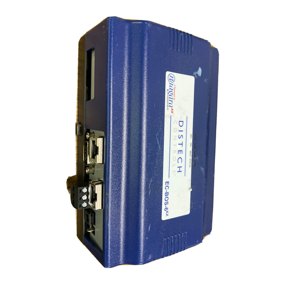
This document covers the mounting and wiring of the EC-BOS-6
series controller. It assumes that you are an engineer, technician, or
service person who is performing control system installation.
Instructions in this document apply to the following products:
Models
Models
Models
Models
Description
Description
Description
Description
AX
EC-BOS-6
EC-BOS-6
(either):
EC-NPB-PWR
DIN-mountable 24V power module
EC-NPB-PWR-UN DIN-mountable 90-263VAC power module
EC-WPM-XX
Wall-mount universal AC power adapter, with
different models available, where -XX is either:
-US, -EU, or -UK (vary by AC wall plug).
Not covered in this document is the Niagara
Note
fully functioning unit. This includes setting host IP address and password, serial port configuration, and
other parameters. Refer to the EC-BOS
In addition, the mounting and wiring of EC-BOS-6
documents. See sections
These are the main topics included in this document:
Preparation,
page 2
•
Precautions,
page 4
•
Mounting,
page 5
•
Board Layout,
page 7
•
About Expansion Options,
•
Wiring Details,
page 11
•
Power Up and Initial Checkout,
•
Also included in this document are several appendixes, as follows:
Using Status LEDs,
•
Maintaining the EC-BOS-6
•
Replacement Parts,
•
Certifications,
page 24
•
Declaration of Conformity,
•
Information and specifications published here are current as of the date of publication of this document. Distech Controls, Inc. reserves the right to change or
modify specifications without prior notice. The latest product specifications can be found by contacting our corporate headquarters. Products or features con-
tained herein may be covered by one or more U.S. or foreign patents. LON and L
work is a trademark of Tridium Inc. © 2008 Distech Controls, Inc.
AX
EC-BOS-6
Mounting and Wiring Instructions
Part Number: 05DI-HIBS6AX-10
EC-BOS-6
AX
base unit controller, powered by
AX
Install and Startup Guide for this information.
"About Expansion Options,"
page 8
page 16
page 19
AX
,
page 20
page 21
page 25
Revised: February 2008
AX
AX
AX
software installation and configuration required for a
AX
expansion options are covered in separate
page 8, and
"Related Documentation,"
W
are registered trademarks of the Echelon Corp. Niagara
ON
ORKS
page 18.
AX
Frame-
1
Advertisement
Table of Contents

Related Manuals for Distech Controls EC-BOS-6AX


Summary of Contents for Distech Controls EC-BOS-6AX
- Page 1 • Information and specifications published here are current as of the date of publication of this document. Distech Controls, Inc. reserves the right to change or modify specifications without prior notice. The latest product specifications can be found by contacting our corporate headquarters. Products or features con- tained herein may be covered by one or more U.S.
-
Page 2: Included In This Package
Preparation Included in this Package Preparation Unpack the EC-BOS-6 and power module (either EC-NPB-PWR, EC-NPB-PWR-UN or EC-WPM-XX) and inspect the contents of the packages for damaged or missing components. If damaged, notify the appropriate carrier at once and return any damaged components for immediate repair or replacement. See “Federal Communications Commission (FCC)”... - Page 3 Preparation Material and Tools Required Suitable screws and screwdriver for mounting DIN rail, or if DIN rail not used, for mounting bases of • EC-BOS-6 controller and power module (if used). #2 phillips screwdriver: used to install and remove optional communications modules. •...
-
Page 4: Safety Precautions
Precautions Safety Precautions Precautions This document uses the following warning and caution conventions: Cautions remind the reader to be careful. They alert readers to situations where there is a chance Caution that the reader might perform an action that cannot be undone, might receive unexpected results, or might lose data. -
Page 5: Environmental Requirements
Mounting Environmental Requirements Mounting Mount the EC-BOS-6 controller in a location that allows clearance for wiring, servicing, and module removal. Additional mounting information applies, as follows: Environmental Requirements • Physical Mounting • Environmental Requirements Note the following requirements for the EC-BOS-6 mounting location: This product is intended for indoor use only. -
Page 6: Mounting On Din Rail
Mounting Physical Mounting Slide the accessory along the DIN rail to connect its 20-position plug into the EC-BOS-6 Step 5 Repeat this for all accessories, until all are mounted on the DIN rail and firmly connected to each other. Step 6 To keep the final assembly together, secure at both ends with DIN rail provided by the DIN Step 7... -
Page 7: Removing And Replacing The Cover
Board Layout Removing and Replacing the Cover Removing and Replacing the Cover You must remove the EC-BOS-6 cover to connect the battery (new unit) or to replace the battery, and to install any option boards. The cover snaps onto the base with four plastic tabs (two on each end). To remove the cover, press in the four tabs on both ends of the unit, and lift the cover off. -
Page 8: About Expansion Options
About Expansion Options About Option Cards About Expansion Options The EC-BOS-6 provides for field-installable expansion with two kinds of options: Option cards—Install on connectors inside the EC-BOS-6 base unit. See “About Option Cards” below. • Accessory modules—To “chain” onto the EC-BOS-6 ’s 20-pin connector. - Page 9 About Expansion Options About Accessory Modules Carefully insert the pins of the option card into the socket of the appropriate option card slot. Step 5 The mounting holes on the option board should line up with the standoffs on the base board. If they do not, the connector is not properly aligned.
- Page 10 About Expansion Options About Accessory Modules Table 2 EC-BOS-6 accessory modules. Model Model Description Description Notes Notes Model Model Description Description Notes Notes EC-Net IO-16 DIN-mountable, 16 points I/O module, Provides the following I/O points: used to provide I/O points as noted. •...
-
Page 11: Wiring Details
Wiring Details Grounding Wiring Details Figure 2 on page 7 to locate connectors and other components on the EC-BOS-6 controller. Make connections to the EC-BOS in the following order. Install any option boards (LON, RS-485, or modem) in option slots 1 and 2. See “Mounting Option Cards,”... - Page 12 Wiring Details Power Wiring Do not connect both the EC-WPM-XX and EC-NPB-PWR/-UN supplies at the same time, or Caution equipment damage may result. If desired, you can use the wall mount EC-WPM-XX in your office (to initially commission the EC-BOS-6 and then install the EC-BOS-6 at the job using an EC-NPB-PWR/-UN module.
- Page 13 Wiring Details Power Wiring Figure 3 EC-NPB-PWR module wiring connections. Power Module (cover shown removed) EC-BOS-6 Earth Ground Dedicated 24Vac Transformer 24Vdc Power Supply neither side of secondary tied (Polarity Not Critical) to earth ground neither side tied to earth Line Voltage 24Vac 24Vdc...
-
Page 14: Communications Wiring
Wiring Details Communications Wiring Figure 4 EC-NPB-PWR-UN module wiring connections. Remove cover 6-pin connector EC-BOS-6 not used or EC-Net IO-16 Note: The 6-pin connector of the EC-NPB-PWR-UN is not used with an EC-BOS-6 series controller. AC Input 120 or 240Vac 50-60Hz Single Phase Line... - Page 15 Wiring Details Communications Wiring Prior to connecting cables, provide strain relief for them to prevent damage to the controller. Note Figure 5 EC-BOS-6 bottom side (cover removed). Ethernet (RJ-45) Primary Ethernet (RJ-45) LAN 2 LAN 1 Battery in bracket (on top of option cards, if any) 20 Pin Connector s + –...
-
Page 16: Power Up And Initial Checkout
Power Up and Initial Checkout Communications Wiring If a modem option card (EC-NPB-MDM) is installed, this port becomes disabled—except if rebooted Note with the mode jumper (see Figure 2 on page 7) in the “Serial Shell” position. Table 3 Serial port (RS-232 and RS-485) pinouts. Base RS-232 DB-9 Port (COM1) Base RS-232 DB-9 Port (COM1) Base RS-232 DB-9 Port (COM1) -
Page 17: Connect The Backup Battery
Power Up and Initial Checkout Connect the Backup Battery Connect the Backup Battery With the cover removed from the EC-BOS-6 (see “Removing and Replacing the Cover,” page 7), locate the red and black wires coming from the backup battery, with 2-position connector plug. Insert the plug into the battery connector on the bottom board (below option slot 2 area), as shown in Figure Figure 6... -
Page 18: About The Battery
Related Documentation About the Battery About the Battery The EC-BOS-6 is provided with a custom 10-cell NiMH battery pack mounted to the unit (under the cover). This battery allows the EC-BOS to continue operation through very short power bumps (a few seconds in duration). -
Page 19: Using Status Leds
Using Status LEDs Ethernet Ports Using Status LEDs The EC-BOS-6 controller includes several LEDs that can help determine the status of the unit. They are located in two places: the top of the controller (visible through the cover), and for serial ports, on the bottom board (only with cover removed). -
Page 20: Replacing The Battery
Maintaining the EC-BOS-6 Cleaning The green receive LED indicates that the EC-BOS-6 is receiving data from a connected device. • These LEDs provide a fixed on-time when data is detected on the port. If these LEDs are on constantly, this indicates a problem with the communications channel, such as a shorted wire or reversed wiring. -
Page 21: Replacement Parts
This fuse provides protection from internal shorts or connection to incorrect power supplies. If the fuse circuitry is suspect, contact Distech Controls office for technical support. See the “Federal Communications Commission (FCC)”... -
Page 22: Standard Replacement Parts
If the faulty EC-BOS-6 is still in warranty, you can receive credit by returning it to Distech Controls. Be sure to contact Distech Controls for a return authorization (RMA) number before shipping an item for return credit. “Federal Communications Commission (FCC),”... - Page 23 Replacing the base assembly New Replacement Units Unplug all Ethernet, serial, LON, and modem connectors from the EC-BOS-6 , and unplug its earth Step 4 ground wire. If I/O accessory modules are installed: Step 5 If DIN rail mounting with DIN end-clips was used, you may be able to remove the DIN rail end clip –...
-
Page 24: Federal Communications Commission (Fcc)
Certifications Federal Communications Commission (FCC) Certifications Federal Communications Commission (FCC) This equipment generates, uses, and can radiate radio frequency energy, and if not installed and used in accordance with the instruction manual, may cause interference with radio communications. It has been tested and found to comply with the limits for a Class A computing device pursuant to Subpart J of Part 15 of FCC Rules, which are designed to provide reasonable protection against such interference when operated in a commercial environment. -
Page 25: Declaration Of Conformity
Application of Council Directive: Application of Council Directive: Application of Council Directive: 89/336/EEC, 92/31/EEC, 73/23/EEC, 93/68/EEC Manufacturer’s Name: Manufacturer’s Name: Manufacturer’s Name: Manufacturer’s Name: Distech Controls, Inc. Manufacturer’s Address: Manufacturer’s Address: Manufacturer’s Address: Manufacturer’s Address: 4005-B Matte Boulevard Brossard, Quebec J4Y 2P4 Canada... - Page 26 Tab Mounting Dimensions 4.32mm Dia. 170.66mm (6.719”) (0.170”) EC-BOS-6 95.25mm (3.75”) 63.50mm 101.6mm Note: Electronic and printed versions of this (2.50”) (4.00”) guide may not show the dimensions to scale. DIN mounting is recommended over tab mounting. EC-Net IO-16 or EC-Net EC-NPM-PWR or EC-BOS-6...
- Page 28 Distech Controls Inc. 05DI-HIBS6AX-10 4005-B Boul. Matte Brossard, QC J4Y 2P4 Tel.: 1-800-404-0043 (North America) 05DI-HIBS6AX-10 Tel.: 1-450-444-9898 (International)
Need help?
Do you have a question about the EC-BOS-6AX and is the answer not in the manual?
Questions and answers