Table of Contents
Advertisement
Quick Links
Advertisement
Table of Contents

Related Manuals for Dell EMC PowerEdge MX7000


Summary of Contents for Dell EMC PowerEdge MX7000
- Page 1 Dell EMC VMware Cloud Foundation for PowerEdge MX7000 Deployment Guide...
- Page 2 Notes, cautions, and warnings NOTE: A NOTE indicates important information that helps you make better use of your product. CAUTION: A CAUTION indicates either potential damage to hardware or loss of data and tells you how to avoid the problem. WARNING: A WARNING indicates a potential for property damage, personal injury, or death.
-
Page 3: Table Of Contents
Option 1—single PowerEdge MX7000 enclosure....................22 Option 2—single PowerEdge MX7000 with MX5016s storage sled..............22 Option 3—two PowerEdge MX7000 enclosures....................23 Option 4—two PowerEdge MX7000 with MX5016s storage sled..............23 Option 5—two PowerEdge MX7000 enclosures using Fabric Switching Engine..........24 Contents... - Page 4 Cabling for a single PowerEdge MX7000 enclosure configuration..............25 Cabling for a dual MX7000 enclosure configuration..................... 26 Cabling for a dual PowerEdge MX7000 enclosure configuration using Fabric Switching Engines....28 7 Cloud Foundation and SDDC design considerations..................32 External services overview............................. 32 Active Directory................................33...
- Page 5 Configure jumbo frames..............................59 Server templates................................60 Create a server template............................60 Associate server template with a VLAN......................... 60 Deploy the server template............................61 11 Map PowerEdge MX5016s storage sled drives....................62 Assumptions..................................62 Prerequisites..................................62 Map drives to compute sleds............................62 12 Deploy ESXi to cluster nodes........................66 Prerequisites..................................
-
Page 6: Audience And Scope
The scope of this document excludes existing infrastructure components outside of the specific hardware and software that is mentioned in this guide. Dell EMC takes no responsibility for any issues that may be caused to existing infrastructure during deployment. Audience and scope... -
Page 7: Overview
Foundation software on the Dell EMC PowerEdge MX7000 hardware that is described in this document has been validated in Dell EMC labs and certified by VMware. The PowerEdge MX7000 systems that are described within are certified as vSAN Ready Nodes, as shown in VMware Compatibility Guide (VCG). - Page 8 Figure 1. Cloud Foundation deployment workflow Overview...
-
Page 9: Pre-Deployment Requirements
Pre-deployment requirements Management host The deployment of VMware Cloud Foundation is executed by a Cloud Builder VM that is deployed using an Open Virtualization Appliance (OVA). The virtual machine must be deployed on an ESXi host or cluster that is not a part of the Cloud Foundation cluster. If the management network is a private network (as it is in this example), then deploy an NTP server and a DHCP server on a management host. -
Page 10: Domain Name Service
NOTE: Misconfiguration or lack of one of these services causes the validation portion of the installation to fail. The information pertaining to the network services are inserted into the Cloud Builder Deployment Parameter Sheet. The parameter sheet is a spreadsheet that contains the details of the deployment and information specific to these prerequisites. Domain Name Service Domain Name Service (DNS) is required to provide both forward and reverse name resolution. -
Page 11: Validated Components
The number of capacity drives in a host is cleanly divisible by the number of cache drives (that is, the result is a whole number) Table 1. Hardware components Manufacturer Model Description Specifications Dell EMC PowerEdge MX7000 Chassis Dell EMC PowerEdge MX740c Compute sled 2x Xeon Gold processor, 256 GB RAM, Cache drives... -
Page 12: Software And Firmware
Software and firmware NOTE: VMware Compatibility Guide (VCG) is the system of record for versions of certain types of firmware and drivers which are certified to be compatible with vSphere and vSAN. These include server platform, vSAN disk controllers, and network interface cards. -
Page 13: Software
1.6.13 iDRAC 3.30.30.30 QLogic 2x25 GbE and 14.07.07 3.7.9.1 QL41232HMKR HBA 330 MX 16.17.00.03 lsi_msgpt3 version 17.00.01.00-1OEM.670 HBA 330 MMZ 16.17.00.03 lsi_msgpt3 version 17.00.01.00-1OEM.670 PowerEdge MX7000 chassis 1.00.10 PowerEdge MX5016s storage sled 2.40 PowerEdge MX5000s storage IOM 1.0.9.6 Validated components... -
Page 14: Hardware Overview
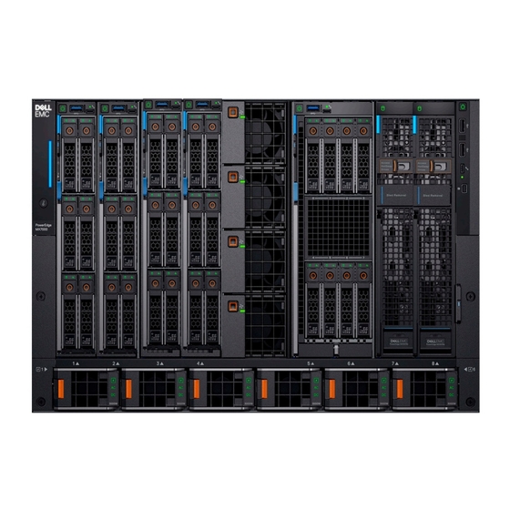
High-speed technology connections, now and into the future, with no mid-plane upgrade. Front view of the PowerEdge MX7000 chassis The front of the PowerEdge MX7000 chassis provides access to compute and storage sleds, fans, KVM, and power supplies. The configuration in the image below includes the following components: •... -
Page 15: Back View Of The Poweredge Mx7000 Chassis
Figure 3. PowerEdge MX7000 chassis—front view Back view of the PowerEdge MX7000 chassis The back of the PowerEdge MX7000 chassis provides access to network and storage fabrics, management modules, fans, and power connections. The configuration in the image below includes the following components: •... -
Page 16: Dell Emc Poweredge Mx740C Compute Sled
Dell EMC PowerEdge MX740c compute sled Dell EMC PowerEdge MX740c is a two-socket, full-height, single-width compute sled that offers high performance and scalability. It is ideal for dense virtualization environments and can serve as a foundation for collaborative workloads. The PowerEdge MX7000 chassis supports up to eight PowerEdge MX740c sleds (if no other sleds are used, such as PowerEdge MX5016s storage sleds) •... -
Page 17: Dell Emc Poweredge Mx5016S Storage Sled
MX740c and the PowerEdge MX840c compute sleds can share drives with the PowerEdge MX5016s sled using the PowerEdge MX5000s SAS module. Internal server drives may be combined with up to seven PowerEdge MX5016s sleds in one chassis for extensive scalability. The PowerEdge MX7000 chassis supports up to seven PowerEdge MX5016s storage sleds. NOTE: SATA and NVMe devices are not supported in the PowerEdge MX5016s storage sled (it is SAS only). -
Page 18: Dell Emc Poweredge Mx9002M Management Module
The Dell EMC PowerEdge MX9002m management module controls the overall chassis power, cooling, and hosts the OpenManage Enterprise-Modular (OME-M) console. Two external 1G-BaseT Ethernet ports are provided to enable management connectivity and to connect more PowerEdge MX7000 chassis into a single logical chassis. The PowerEdge MX7000 chassis supports two PowerEdge MX9002m management modules for redundancy. -
Page 19: Dell Emc Networking Mx9116N Fabric Switching Engine
Expander Module. The QSFP28-DD ports also provide capacity for extra uplinks, VLTi links, and connections to rack servers at 10 GbE or 25 GbE using breakout cables. The PowerEdge MX7000 chassis supports up to four MX9116n FSEs in Fabric A or B, or both. -
Page 20: Dell Emc Networking Mx5108N Ethernet Switch
Dell EMC Networking MX5108n Ethernet switch The Dell EMC Networking MX5108n Ethernet switch is targeted at small PowerEdge MX7000 deployments of one or two chassis. Although not a scalable switch, it still provides high-performance and low latency with a non-blocking switching architecture. The MX5108n switch provides line-rate 25 Gbps Layer 2 and Layer 3 forwarding capacity to all connected servers with no oversubscription. - Page 21 PCIe slot. The PowerEdge MX5000s switches are deployed as redundant pairs to offer multiple SAS paths to the individual SAS disk drives. The PowerEdge MX7000 chassis supports redundant PowerEdge MX5000s in Fabric C. Figure 12. Dell EMC PowerEdge MX5000s storage sled...
-
Page 22: Physical Layout
Physical layout There are multiple configurations of Cloud Foundation on PowerEdge MX7000 chassis that are described in this document. The Cloud Foundation software addresses the host servers using their IP Address. Deploying compute sleds across multiple PowerEdge MX7000 chassis has no impact on the software as long as the networking is configured properly on the Networking IO modules and the switches to which the PowerEdge MX7000 chassis connects. -
Page 23: Option 3-Two Poweredge Mx7000 Enclosures
Figure 14. Single PowerEdge MX7000 with MX5016s storage sled Option 3—two PowerEdge MX7000 enclosures • Two Dell EMC PowerEdge MX7000 enclosures • Four Dell EMC PowerEdge MX740c compute sleds • Four Dell EMC Networking MX5108n Ethernet switches Figure 15. Two PowerEdge MX7000 enclosures Option 4—two PowerEdge MX7000 with MX5016s storage... -
Page 24: Option 5-Two Poweredge Mx7000 Enclosures Using Fabric Switching Engine
Figure 16. Two PowerEdge MX7000 with MX5016s storage Option 5—two PowerEdge MX7000 enclosures using Fabric Switching Engine • Two or more (up to a maximum of 10) Dell EMC PowerEdge MX7000 enclosures • Four Dell EMC PowerEdge MX740c compute sleds •... -
Page 25: Cabling
The following figure shows the external cabling for a single PowerEdge MX7000 enclosure configuration. The Customer Network Link Aggregation is shown here as an example as the upper layer connection is not specified but it must use an LACP enabled Link Aggregation (LAG). -
Page 26: Cabling For A Dual Mx7000 Enclosure Configuration
Cabling for a dual MX7000 enclosure configuration The following figure shows the external cabling for a multiple PowerEdge MX7000 enclosure configuration. The Customer Network Link Aggregation is shown as an example as the upper layer connection is not specified except that it must use an LACP enabled Link Aggregation (LAG). - Page 27 Figure 19. Dual PowerEdge MX7000 enclosure configuration Physical layout...
-
Page 28: Cabling For A Dual Poweredge Mx7000 Enclosure Configuration Using Fabric Switching Engines
LACP enabled Link Aggregation (LAG). You can add more enclosures (up to a maximum of 10) that connect back to the upper level devices in the infrastructure. Additional PowerEdge MX7000 enclosures require only two MX7116n Fabric Expansion Modules whose ports appear as additional ports on the MX9116n Fabric Switching Engines on the first two PowerEdge MX7000 enclosures. - Page 29 Figure 20. MX9002m Management module cabling Physical layout...
- Page 30 Figure 21. Connectivity between FSE modules and FEM modules Physical layout...
- Page 31 Figure 22. Uplinks to customer network environment Physical layout...
-
Page 32: Cloud Foundation And Sddc Design Considerations
Cloud Foundation and SDDC design considerations VMware Cloud Foundation relies on a set of key infrastructure services to be made available externally. You must configure these external services before you begin deployment. NOTE: This section is universal for Cloud Foundation deployments regardless of hardware platform. The content in this section is also available in the VMware Cloud Foundation Planning and Preparation Guide, and is included here for reference. -
Page 33: Active Directory
Active Directory Cloud Foundation uses Active Directory (AD) for authentication and authorization to resources. The Active Directory services must be reachable by the components that are connected to the management and vRealize networks. You must configure user and group accounts in AD before adding them to the SDDC manager and assigning privileges. NOTE: If you plan to deploy vRealize Automation, Active Directory services must be available. -
Page 34: Certificate Authority (Optional)
Certificate Authority (optional) The components of the SDDC require SSL certificates for secure operation. During deployment, self-signed certificates are used for each of the deployed components. These certificates can be replaced with certificates that are signed by an internal enterprise CA or by a third- party commercial CA. -
Page 35: Host Names And Ip Addresses
Table 5. VLANs and IP subnets for a sample deployment Workload Domain Cluster VLAN Function VLAN ID Subnet Gateway Management Cluster-01 Management 1611 172.16.11.0/24 172.16.11.253 vMotion 1612 172.16.12.0/24 172.16.12.253 vSAN 1613 172.16.13.0/24 172.16.13.253 VXLAN (NSX VTEP) 1614 172.16.14.0/24 172.16.14.253 vRealize Suite 1616 172.16.16.0/24 172.16.16.253... -
Page 36: Host Names And Ip Addresses For The Virtual Infrastructure Layer
Table 6. Configuration for external services Component Group Hostname IP Address Description sfo01.rainpole.local Round-robin DNS pool containing the NTP servers 0.ntp sfo01.rainpole.local 172.16.11.251 First NTP Server 1.ntp sfo01.rainpole.local 172.16.11.252 Second NTP Server AD or DNS or CA dc01rpl rainpole.local 172.16.11.4 Windows 2012 R2 host that contains the AD configuration, the DNS... -
Page 37: Host Names And Ip Addresses For The Operations Management Layer
Workload Domain Hostname DNS Zone IP Address Description sfo01m01esx03 sfo01.rainpole.local 172.16.11.103 ESXi host 03 sfo01m01esx04 sfo01.rainpole.local 172.16.11.104 ESXi host 04 sfo01m01nsx01 sfo01m01nsxc01 sfo01m01nsxc02 sfo01m01nsxc03 Host names and IP addresses for the operations management layer The operations management layer focuses on the components used for day-to-day management of the Cloud Foundation environment. Cloud Foundation automatically deploys vRealize Log Insight in the management domain during deployment. -
Page 38: Networking Requirements
This section covers the networking requirements from both the Cloud Foundation software perspective and from a networking hardware connectivity perspective. This section also briefly describes the configuration options for configuring networks on a Dell EMC PowerEdge MX7000 chassis. The actual networking configuration procedures are described in the later sections. -
Page 39: Network Configuration Options
The FSEs are installed into the A1 fabric of the first chassis and the A2 fabric of the second chassis. The FEMs are distributed across both PowerEdge MX7000 chassis in the remaining A fabric slots. The FEMs connect back to the FSEs using a double data rate, 200 Gbps cable. - Page 40 Figure 23. Single PowerEdge MX7000 chassis—network connectivity using MX5108n Ethernet switches When deploying multiple PowerEdge MX7000 chassis, the network connectivity is as shown in the following figures. Networking requirements...
- Page 41 Figure 24. Multiple PowerEdge MX7000 chassis—network connectivity using MX5108n Ethernet switches Networking requirements...
- Page 42 Figure 25. MX9002m Management Module cabling Networking requirements...
- Page 43 Figure 26. Connectivity between FSE modules and FEM modules Networking requirements...
- Page 44 Figure 27. Uplinks to customer network environment Networking requirements...
-
Page 45: Vlan And Subnets For Networking Configuration
Configuring jumbo frames is a best practice for both vMotion and vSAN networks, both of which are core components of Cloud Foundation. All the switch ports on the modular switches and up to the aggregation switches used to connect multiple PowerEdge MX7000 enclosures together must be configured for jumbo frames. -
Page 46: Manual Switch Configuration
Manual switch configuration This section describes the configuration of the MX5108n switches. Each PowerEdge MX7000 chassis has two MX5108n switches in the A fabric (A1 and A2). Each of the two switches gets the same configuration except for the IP address and the VLT Backup Destination IP Address. -
Page 47: Uplink And Vlti Ports
VLT synchronizes Layer 2 table information between the switches and enables them to display as a single logical unit from outside the VLT domain. The VLT interconnect (VLTi) between the two Dell EMC MX5108n switches is a port group that is generated by configuring a VLT domain and specifying the discovery interfaces. -
Page 48: Configure The Ports For Vlti
Eth 1/1/14 down full Eth 1/1/15 down full ------------------------------------------------------------------------------- MX7K-IOM-A2# configure terminal MX7K-IOM-A2(config)# interface breakout 1/1/10 map 40g-1x Configure the ports for VLTi The VLTi ports for this example are Ethernet 1/1/9 and Ethernet 1/1/10:1. These ports are placed into a link aggregation by the VLT configuration process. -
Page 49: Verify The Vlti (Port-Channel)
Protocol After the VLT is enabled, create the uplink to the network layer above the PowerEdge MX7000 enclosure. The connection should be an Link Aggregation Control Protocol (LACP) active link aggregation of two ports. The MX5108n switches support uplink speeds of 100 GbE, 40 GbE, or 25 GbE on Ethernet port 1/1/11. -
Page 50: Configure The Server Facing Ports
Configure the server facing ports To support multiple VLANs, you must place the server facing ports in trunk mode. All the VLANs assigned to the ports are tagged to allow the port groups to identify and direct traffic appropriately. MX7K-IOM-A2# configure terminal MX7K-IOM-A2(config)# interface range ethernet 1/1/1-1/1/8 MX7K-IOM-A2(conf-range-eth1/1/1-1/1/8)# switchport trunk allowed vlan 96,1611-1614,2711-2712 MX7K-IOM-A2(conf-range-eth1/1/1-1/1/8)# mtu 9216... - Page 51 no shutdown mtu 9216 interface vlan 2712 description Edge-Uplink no shutdown mtu 9216 interface vlan4020 mgmt no shutdown ip address dhcp ipv6 address autoconfig interface port-channel1 description VLT-uplink no shutdown switchport mode trunk switchport access vlan 1 switchport trunk allowed vlan 96,1611-1614,2711-2712 mtu 9216 vlt-port-channel 1 interface ethernet1/1/1...
- Page 52 mtu 9216 interface ethernet1/1/7 no shutdown fec off switchport mode trunk switchport access vlan 1 switchport trunk allowed vlan 96,1611-1614,2711-2712 mtu 9216 interface ethernet1/1/8 no shutdown fec off switchport mode trunk switchport access vlan 1 switchport trunk allowed vlan 96,1611-1614,2711-2712 mtu 9216 interface ethernet1/1/9 description VLTi...
- Page 53 class-map type qos class-trust class-map type qos CM1 match vlan 1 vlt-domain 101 backup destination 100.71.96.121 discovery-interface ethernet1/1/9,1/1/10:1 vlt-mac 00:11:22:33:55:66 Manual switch configuration...
-
Page 54: Smartfabric Network Configuration
SmartFabric topologies is facilitated using the OME-Modular console. SmartFabric is a web-based mechanism to create a reusable networking template that can be applied to a PowerEdge MX7000 chassis, the IO modules (switches) and the compute sleds. SmartFabric creates and configures the switches based on networking best practices. By selecting the topology, SmartFabric creates the VLT domain and VLTi connections and creates the uplink LACP enabled link aggregations. - Page 55 Figure 28. Chassis PowerEdge MX9002m cabling Steps After the PowerEdge MX9002m modules have been cabled together, log in to the OME-Modular web interface of the chassis that will be the lead chassis of the new chassis group. From the Chassis Overview menu, click Configure, and then select Create Chassis Group. Enter the group name and group description.
-
Page 56: Define Networks
Figure 30. Group topology Define networks Prerequisites Networks or subnets should be defined to meet the Cloud Foundation requirements. The prerequisites to define networks are as follows: Create chassis groups Cloud Foundation management network vMotion network vSAN network VXLAN network Uplink1 network Uplink2 network To define networks using the OME-Modular console, perform the following steps:... -
Page 57: Create Smartfabric
Create SmartFabric Creation of the SmartFabric depends on the IOM selected and the number of PowerEdge MX7000 chassis to be installed. The devices eligible for SmartFabric deployment are: • MX5108n Ethernet switch • MX9116n Fabric Switching Engine • MX7116n Fabric Expansion Module When deploying the MX5108n switch, create chassis groups for improved management but the IOMs in each chassis function independently of the IOMs in other chassis. -
Page 58: Create Smartfabric Using Mx9116N Fabric Switching Engine Ioms
2x MX9116n Fabric Switching Engines in different chassis Figure 33. Create SmartFabric using MX9116n Fabric Switching Engine IOMs From the Chassis-X list, select the first PowerEdge MX7000 chassis containing an MX9116n FSE. From the Switch-A list, select Slot-IOM-A1. From the Switch-B list, select Slot-IOM-A2. -
Page 59: Configure Jumbo Frames
In the Add Uplink window, complete the following steps: Enter the name in the Name box. b Enter the description in the Description box. From the Uplink Type list, select Ethernet. d Click Next. From the Switch Ports list, select the appropriate Ethernet ports: Ethernet 1/1/11 from both MX5108n IOMs Ethernet 1/1/41 and Ethernet 1/1/42 from both MX9116n IOMs From the Tagged Networks list, select all four Cloud Foundation VLANs. -
Page 60: Server Templates
Select ports Ethernet 1/1/1-Ethernet 1/1/8 and the uplink port channel. Click Configure MTU and set MTU to 9216. Click Finish. Jumbo frames that are required for the Cloud Foundation are configured. Server templates A server template contains the parameters that are extracted from a server and allows the parameters to be quickly applied to multiple compute sleds. -
Page 61: Deploy The Server Template
Click Finish. The server template is associated with the VLAN network. Deploy the server template Prerequisite Before deploying the server template, you must associate the server template with a VLAN. About this task To deploy the server template, perform the following steps: Steps In the Deploy pane, select the MX740c with Intel mezzanine server template, and then click Deploy Template. -
Page 62: Map Poweredge Mx5016S Storage Sled Drives
There are multiple configurations covered as part of this deployment guide. This section covers one specific example (listed below) out of these possible configurations. The process for other configurations which include PowerEdge MX5016s would be very similar. Following is the example configuration for PowerEdge MX7000: •... - Page 63 Figure 35. OME-Modular web interface—Devices and storage page Select Edit Assignments. Select the check boxes for slots 0,1,2, and 3 and then click Assign Drive to Slot. Map PowerEdge MX5016s storage sled drives...
- Page 64 Figure 36. OME-Modular web interface—Edit assignment page In the Assign Hard Drive to Compute window, select Slot 1 / Sled 1, and then click Assign. Assignment for slots 0-3 is set to compute Slot 1 / Sled 1. Map PowerEdge MX5016s storage sled drives...
- Page 65 Figure 37. Assign Hard Drive to Compute page Repeat steps 4-7 to map the remaining drives as shown in the following table: Table 11. Mapping of PowerEdge MX5016s drive to storage sled Chassis PowerEdge MX5016s Drives Assign to Sled/Slot 4–7 0–3 4–7 Map PowerEdge MX5016s storage sled drives...
-
Page 66: Deploy Esxi To Cluster Nodes
The virtual console should be in HTML5 mode, which is the default setting. • The location of the Dell EMC customized ESXi image (ISO image) file should not be changed during the installation process. Steps Using a web browser, go to Open Manage Enterprise Modular (embedded chassis management) web interface at https://<OME Modular Address>. - Page 67 The mapping screen for the virtual media is displayed on the Virtual Media menu. In the Map CD/DVD section, click Choose File. Browse and select the required Dell EMC customized ESXi image (ISO image) file. Click Map Device and then click Close.
-
Page 68: Install Vmware Esxi
Figure 39. Virtual media mapping page From the Virtual Console menu, click Boot, and then click Virtual CD/DVD/ISO. Click Yes. From the Power menu, click Power on System. If the system is not turned on, click Power on System. If the system is ON, click Power Cycle System (cold boot). The server is connected to the iDRAC devices and boots into the ESXi installer. -
Page 69: Configure Esxi Settings-Using Dcui
Figure 40. ESXi disk partition page Select the required keyboard layout, and then press Enter. Enter the root password, and then press Enter. In the Confirm Install window, press F11 to install the VMware ESXi. In the Installation Complete window, press Enter to reboot the server. The installation completes and the server boots into ESXi. -
Page 70: Configure Esxi Settings Using Web Interface
Figure 41. IPv4 configuration page Enter the IPv4 Address,Subnet Mask, and the Default Gateway, and then press Enter to confirm. Select DNS Configuration, and then press Enter. Enter the IP addresses of the DNS servers and FQDN of the host. Press Esc to return to the main menu, and then press Y to confirm the changes and restart the management network. - Page 71 Figure 42. ESXi web interface—Edit settings page In the Edit Port Group window, enter the Management VLAN ID, and then click Save. CAUTION: Leaving the VLAN ID at default setting causes pre-deployment validation to fail during a later step. In the Navigator pane, click Manage to set up the NTP. In the right pane, click Time &...
- Page 72 Figure 43. ESXi web interface—Edit time configuration page In the Manage pane, select Actions > NTP Service > Start. The resulting page is as shown in the following figure: Figure 44. ESXi settings web interface—Manage pane Next step Repeat all the steps for each host targeted for Cloud Foundation management domain deployment. Validate that each ESXi host can access the NTP servers by establishing an SSH connection to each host and executing the ntpq -p command.
-
Page 73: Cloud Builder Ova Deployment
Cloud Builder OVA deployment The primary software installation tool for Cloud Foundation 3.x is Cloud Builder. It is delivered as a virtual appliance in the standard OVA format. This section describes the steps to deploy the OVA. The Cloud Builder VM is a temporary tool to facilitate deployment of Cloud Foundation. - Page 74 Figure 45. ESXi—Hosts and Clusters page Locate the OVA file locally or from the URL, and then click Next. Select the required ESXi server to host the Cloud Builder VM, and then click Next. NOTE: The selected EXSi server should not be targeted for Cloud Foundation deployment. Click Next.
- Page 75 Figure 46. OVF customize template page Review the Ready to Complete final configuration page, and then click Finish. In the Recent Tasks pane, check the OVA deployment status. When the OVA deployment is complete, turn on the Cloud Builder VM. Cloud Builder OVA deployment...
-
Page 76: Running Cloud Builder
Running Cloud Builder In the previous section, you deployed the Cloud Builder virtual appliance. In this section, the software within the virtual machine is used to validate the target environment and deploy the entire Cloud Foundation stack. IMPORTANT: Before proceeding with the Cloud Builder validation process, take a snapshot of your Cloud Builder VM. Topics: •... -
Page 77: Cloud Builder Deployment Parameter Sheet
Figure 47. Cloud Builder web interface Log in using the credentials that you specified during OVA deployment. Click Check All to review the checklist of pre-bring-up steps and confirm that all the steps that are completed, and then click Next. Review the EULA, and if you agree, click Agree to End User License Agreement, and then click Next. -
Page 78: Management Workload Tab
• Users and Groups tab • Hosts and Networks tab • Deploy Parameters tab Management Workload tab License keys are required for the following items: • ESXi hosts • vSAN • • Platform Services Controller Users and Groups tab In the Users and Groups tab, you can set the passwords for your initial Cloud Foundation components. CAUTION: Do not make a mistake on this page because if any of the passwords do not meet the indicated specifications, you must redeploy your Cloud Builder VM, unless you elected to create a snapshot after you created your VM. -
Page 79: Configure Cloud Builder Validation
Configure Cloud Builder validation About this task The Cloud Builder validator is a critical step in the Cloud Foundation deployment process. It probes your target servers, required services, and network environment to detect potential issues. NOTE: The validation may fail initially and can be run as many times as necessary to address any issues. Steps After you have completed the deployment parameter spreadsheet, click Upload, select the file, and then click Open. - Page 80 Steps In the Bringing Up the SDDC page, click Next to start the deployment of Cloud Foundation. NOTE: You can monitor the deployment progress on the Bringing Up the SDDC page and this deployment process may require two hours or more, depending on your environment. If a bring-up failure occurs, expand the failed line item, review the detailed error messages.
-
Page 81: Post-Install Validation
Post-install validation Cloud Foundation Cluster Verification After installing Cloud Foundation, perform the steps in the following sections to verify that the components are installed and available. SDDC Manager Log in to SDDC Manager using a web browser at: https://<ip address or DNS name>. The SSO user ID is administrator@vsphere.local and the password is the one you specified during installation. -
Page 82: Cluster And Vms
Cluster and VMs From the vCenter console, review the virtual machines created by CloudBuilder. You should see 11 VMs running with their Status indicating Normal. Figure 51. Cluster and VMs vSAN About this task Review the vSAN Disk Groups in vCenter by performing the following steps: Steps On the Hosts and Clusters tab, select the management cluster. - Page 83 Steps In the vCenter interface, select the Home menu. Select Network and Security from the drop-down list. The NSX dashboard is displayed as shown in the following figure: Figure 53. NSX dashboard Post-install validation...
Need help?
Do you have a question about the PowerEdge MX7000 and is the answer not in the manual?
Questions and answers