Table of Contents
Advertisement
Quick Links
See also:
Manual
Advertisement
Table of Contents
Troubleshooting

Related Manuals for WEIHONG NK280


Summary of Contents for WEIHONG NK280
- Page 1 NK280 Integrated CNC System Manufacturers’ Manual 2nd Edition Weihong Electronic Technology Co., Ltd.
- Page 2 The copyright of this manual belongs to Weihong Electronic Technology Co., Ltd. (hereinafter referred to as Weihong Company). This manual and any image, table, data or other information contained in this manual may not be reproduced, transferred, or translated without any prior written permission of Weihong Company.
- Page 3 Appendix part, including chapter 7 and 8. Chapter 7 lists all the parameters while chapter 8 contains the software license agreement. Applicable Product Models This manual is applicable to NK280 integrated CNC system. Refer to the table below for details. Product Model Remarks Abbreviated as NK280;...
- Page 4 上海维宏电子科技股份有限公司 Weihong Electronic Technology Co., Ltd. Revision History You can refer to the following table for the revision records of each edition. Please note that content in this manual is subjected to change. Date Edition Revision 2016.02 Contact information updated.
- Page 5 上海维宏电子科技股份有限公司 Weihong Electronic Technology Co., Ltd. WARNING Precautions Related to Storage and Transportation The products should be transported properly in terms of the weight; An excess of specified quantity of stacking products is prohibited; Climbing, standing or placing heavy loads on the products is prohibited;...
- Page 6 上海维宏电子科技股份有限公司 Weihong Electronic Technology Co., Ltd. WARNING It is prohibited to plug or open the chassis of CNC device when power on. Precautions Related to Running & Debugging Parameters setting should be checked before running, since wrong setting may lead to accidental movements;...
-
Page 7: Table Of Contents
Contents SUMMARIZATION ........................... - 5 - .......................... - 6 - ARDWARE NTRODUCTION 1.1.1 A Picture of NK280 ..........................- 6 - 1.1.2 System configuration ......................... - 6 - 1.1.3 Mounting Dimension ......................... - 6 - 1.1.4 Host of NK280 ............................ - 7 - 1.1.5... - Page 8 Connection Verification Setup ..................... - 83 - 3.16.3 NK280 Network Files Management by PC via FTP............... - 84 - 3.16.4 NK280 Network Files Management by PC via Network Sharing ..........- 84 - 3.17 ..........................- 86 - UXILIARY UNCTION 3.17.1...
- Page 9 Auto Tool Change of Linear Tool Magazine ................. - 90 - 3.18.2 Auto Tool Change of Circular Tool Magazine ................- 91 - 3.18.3 Related Parameters ........................- 92 - NK280 FOR DUAL Z-AXES MACHINE ...................... - 93 - ........................- 94 - ULTIPLE AXES ONTROL 4.1.1...
- Page 10 上海维宏电子科技股份有限公司 Weihong Electronic Technology Co., Ltd. 6.3.1 Wiring Diagram of WISE Servo Driver ................... - 134 - 6.3.2 Wiring Diagram of YASKAWA AC Servo Driver ................- 135 - 6.3.3 Wiring Diagram of PANASONIC AC Servo Driver................- 136 - 6.3.4...
-
Page 11: Summarization
Weihong Electronic Technology Co., Ltd. 1 Summarization .......................... - 6 - ARDWARE NTRODUCTION 1.1.1 A Picture of NK280 ..........................- 6 - 1.1.2 System configuration ......................... - 6 - 1.1.3 Mounting Dimension ......................... - 6 - 1.1.4 Host of NK280 ............................ - 7 - 1.1.5... -
Page 12: Hardware Introduction
The extended terminal board EX26A is optional. 1.1.3 Mounting Dimension After NK280 is installed on the machine tool, 100 mm space should be preserved in its surrounding for wiring convenience. Please ensure ventilation in the cabinet. And the mounting dimension is shown in Fig. 1-2:... -
Page 13: Host Of Nk280
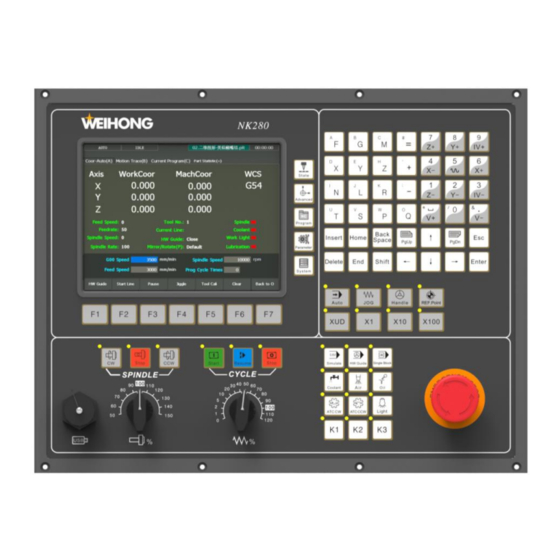
上海维宏电子科技股份有限公司 Weihong Electronic Technology Co., Ltd. 112,2 Fig. 1-2 Mounting dimension of NK280 integrated system 1.1.4 Host of NK280 Front View of NK280 User Interface Function Buttons Keyboard Operation Buttons Manipulation Mode Buttons Buttons Auxiliary Buttons E-stop Button USB Interface... - Page 14 上海维宏电子科技股份有限公司 Weihong Electronic Technology Co., Ltd. User interface: interactive, simple and user-friendly design, featuring convenient operation. Operation buttons: including ―State‖, “Advanced‖, ―Program‖, ―Parameters‖, and ―System‖. Keyboard: each letter key contains one bigger letter and smaller letter, the smaller locating at the top left while bigger one, which supports capital entering only, at the lower right.
- Page 15 Note: When the indicator light at the top left is on, it means the corresponding function is activated. Rear View of NK280 The rear view of NK280 with its interface definition is shown as below. To X To Z...
- Page 16 上海维宏电子科技股份有限公司 Weihong Electronic Technology Co., Ltd. To 4-axis driver: connected to the driver of the fourth axis; To 5-axis driver: connected to the driver of the fifth axis. To I/O board: connected to the terminal board. Refer to chapter 2.2 for the terminal board specifications.
-
Page 17: Connection Schematic Diagram
上海维宏电子科技股份有限公司 Weihong Electronic Technology Co., Ltd. 1.1.5 Connection Schematic Diagram The connection of Y/Z/4-axis/5- Servo axis port is Driver similar to that of X axis. 端子板接口 手轮(MPG) (I/O Board 网口(LAN0) 4Axis 5Axis Interface) DC INPUT 24V2A To 24V Servo Motor... -
Page 18: Software Introduction
Weihong Electronic Technology Co., Ltd. Software Introduction Based on embedded operating system, NK280 can be used as 4-axis system, dual Z axes system, system for key cutting machine and system for knife grinder machine respectively according to different hardware configurations and software versions. This manual takes the standard 4-axis system as an example as a whole, and the unique features of other systems will be introduced separately. -
Page 19: Wiring
上海维宏电子科技股份有限公司 Weihong Electronic Technology Co., Ltd. 2 Wiring ........................- 14 - ASIC ONCEPTS OF IGNAL 2.1.1 Signal Types ............................. - 14 - 2.1.2 Binary Input ............................. - 15 - 2.1.3 Binary Output ..........................- 15 - 2.1.4 Analog Output ..........................- 17 - .................... -
Page 20: Basic Concepts Of Signal
EX6A4; at this time, conducting to 24V in NO connection means signal detected, and disconnecting with 24V in NC connection means signal detected. NK280 dual Z system, system for key cutting machine and system for knife grinder machine do not support high level effective. -
Page 21: Binary Input
上海维宏电子科技股份有限公司 Weihong Electronic Technology Co., Ltd. Terminal Board +24V Analog 47Ω Fig. 2-2 Electric circuit of analog output signal 2.1.2 Binary Input Connection of Binary Input and External Circuit The wiring method between binary input signal and a mechanical switch is shown in Fig. 2-3: I/O Board Card Fig. - Page 22 上海维宏电子科技股份有限公司 Weihong Electronic Technology Co., Ltd. OUTX Fig. 2-5 Equivalent circuit of binary output interface Technical Parameter 1) Supply voltage: 24VDC 2) Binary open-collector output OC (open-collector) outputs drive capability with maximum allowable operating voltage 30VDC and maximum allowable current 20mADC; so when the output terminal is active low, the maximum allowable sucked current is 20mA.
-
Page 23: Analog Output
Wiring Specification of Terminal Board EX9A4 is the terminal board for NK280 standard 4-axis system while EX24A2 for dual Z system, system for key cutting machine and system for knife grinder machine. Another option is EX26A3, used for I/O ports expansion. -
Page 24: Wiring Diagram Of Terminal Board
上海维宏电子科技股份有限公司 Weihong Electronic Technology Co., Ltd. 2.2.1 Wiring Diagram of Terminal Board The wiring diagrams between NK280 and terminal board are shown as follows: Standard 4-axis system NK280 Host Host Interface of Next I/O Interface Terminal Board 24VDC +24V... - Page 25 上海维宏电子科技股份有限公司 Weihong Electronic Technology Co., Ltd. Dual Z System NK280 Host Host Interface of I/O Interface Next Terminal Board 24VDC +24V Power Input MASTER PORT SLAVE PORT 主机接口 从机接口 Inverter Terminal Analog Voltage Analog GND Z1 Axis Brake Output...
- Page 26 上海维宏电子科技股份有限公司 Weihong Electronic Technology Co., Ltd. Extended terminal board Host Interface Slave Interface 24VDC +24V Power Input MASTER PORT SLAVE PORT 主机接口 从机接口 GX01 GX02 GX03 GX04 GX05 Load Range: GX06 AC 250V 10A GX07 DC 30V 10A GX08...
-
Page 27: Port Specification Of Terminal Board
上海维宏电子科技股份有限公司 Weihong Electronic Technology Co., Ltd. 2.2.2 Port Specification of Terminal Board 2.2.2.1 Standard 4-axis System Silk-printed Software Group Description Name Definition External +24V Terminal board should be powered by external DC 24V power power power supply. Binary input, low level effective; connected to X machine origin home switch of X-axis. -
Page 28: Dual Z System
上海维宏电子科技股份有限公司 Weihong Electronic Technology Co., Ltd. Silk-printed Software Group Description Name Definition Connected to the brake output signal of the BRAKE Brake control Z-axis servo driver. brake Two ends of brake Controlling the 24V on/off of the motor brake BK+, BK- input line. - Page 29 上海维宏电子科技股份有限公司 Weihong Electronic Technology Co., Ltd. Silk-printed Software Group Description Name Definition Binary input, low level effective; connected to Z1LAM+ Z1 positive limit positive limit switch of Z1-axis. Binary input, low level effective; connected to Z1LAM- Z1 negative limit negative limit switch of Z1-axis.
-
Page 30: Port Definition And Wiring Specification
Port Definition and Wiring Specification 2.3.1 Driver Interface Definition NK280 host provides 4 pulse-feed driver interfaces, i.e. X, Y, Z and A axes driver interfaces. The type of driver interface is 15-core D socket (DB15 pins). The pin definition is as follows: 15: GND... - Page 31 上海维宏电子科技股份有限公司 Weihong Electronic Technology Co., Ltd. Name Definition Input /Output Description Feedback signal of Input, differential signal A+, A- encoder phase A transmission mode Receive the differential output of Feedback signal of Input, differential signal encoder signal (phase A, B, C)
-
Page 32: Handwheel Interface Definition
Weihong Electronic Technology Co., Ltd. 2.3.2 Handwheel Interface Definition NK280 can be externally connected with a manual pulse generator (MPG, also called handwheel), supporting 6-axis MPG at most, via the DB15 core dual-in-line holes interface. Its pin definition is as shown in Fig. 2-12. -
Page 33: Manipulation
上海维宏电子科技股份有限公司 Weihong Electronic Technology Co., Ltd. 3 Manipulation ............................ - 29 - EBUGGING TEPS ................- 30 - DJUSTMENT OF XIAL IRECTION AND ULSE QUIVALENT 3.2.1 Axial Direction Adjustment ......................- 30 - 3.2.2 Pulse Equivalent Adjustment ......................- 30 - 3.2.3... - Page 34 Connection Verification Setup ..................... - 83 - 3.16.3 NK280 Network Files Management by PC via FTP............... - 84 - 3.16.4 NK280 Network Files Management by PC via Network Sharing ..........- 84 - 3.17 ..........................- 86 - UXILIARY UNCTION 3.17.1...
-
Page 35: Debugging Steps
上海维宏电子科技股份有限公司 Weihong Electronic Technology Co., Ltd. Debugging Steps Debugging starts (1) Refer to Chapter 3.5 “Adjustment of Port Polarity” for adjusting polarity of I/O ports Port detecting is correct or not? False True (2) Refer to Chapter 3.2 “Adjustment of Axial Direction &... -
Page 36: Adjustment Of Axial Direction And Pulse Equivalent
The relationship between Max. feedrate and pulse equivalent is as following: Max. Feedrate= pulse equivalent X 60 X frequency For example, the hardware frequency of NK280 is 320 KHz and provided the pulse equivalent is 0.001 mm/p, then: Max. feedrate=0.001 X 60 X 320000= 19.2m/min... - Page 37 上海维宏电子科技股份有限公司 Weihong Electronic Technology Co., Ltd. the teeth number of driven wheel to that of driving wheel. When applied in CNC machines, it specifies the ratio of motor speed to screw speed. Reducer input speed Driven wheel teeth number Motor speed...
-
Page 38: Upper & Lower Limit Setting Of Workbench Stroke
上海维宏电子科技股份有限公司 Weihong Electronic Technology Co., Ltd. Motor Type: TYPE SGMSH-1 0 A C A 2 1 (The 4th character) The 4th character: serial encoder spec. Sign Spec. Remark 17-bit absolute Standard 17-bit increment Standard Fig. 3-3 Name plate of servo motor-encoder resolution For instance: (an example of YASKAWA servo) screw pitch of a certain type of machine is 5mm, with 17 bit encoder resolution, ―0.0001mm/p‖... - Page 39 上海维宏电子科技股份有限公司 Weihong Electronic Technology Co., Ltd. Related Parameters Definition Parameter Setting Range Workbench range upper limit (X) Workbench range upper They set the allowable machine limit (Y) Related actual coordinate values for the upper limit of specifications of the machine Workbench range upper the worktable.
-
Page 40: Returning To Machine Origin
上海维宏电子科技股份有限公司 Weihong Electronic Technology Co., Ltd. Returning to Machine Origin Origin of Machine Coordinate System (inherent coordinate system of machine tool), also called mechanical origin or mechanical zero, is fixed after design, manufacturing and debugging before machine tool leaving factory. After startup of control system, it is necessary to execute the operation of returning to machine origin automatically or manually. - Page 41 上海维宏电子科技股份有限公司 Weihong Electronic Technology Co., Ltd. Coarse Positioning Stage Legend: C’ Initial stage Stop position after receiving signal Enter into signal zone reversely Leave signal zone reversely Arrow tip indicates the machine stop position Distance Fig. 3-5 Sketch map of coarse positioning (stopping within the signal belt after receiving coarse positioning signal) Legend: C’...
- Page 42 上海维宏电子科技股份有限公司 Weihong Electronic Technology Co., Ltd. C’ Distance Fig. 3-7 The process of fine positioning Retracting Stage After finishing the fine positioning stage, system will execute retracting motion once with the recommended retract distance as half of the screw pitch. The sketch map is shown in Fig. 3-8.
-
Page 43: Parameters Specifications
上海维宏电子科技股份有限公司 Weihong Electronic Technology Co., Ltd. 3.3.2 Parameters Specifications Related Parameters of Safe Operations: Parameter Definition Setting Range Back to reference point Whether backing to machine origin Yes: Required before machining before machining is a must or not. No: Not required... -
Page 44: Faq & Troubleshooting
上海维宏电子科技股份有限公司 Weihong Electronic Technology Co., Ltd. Parameter Definition Setting Range establish the machine coordinate system. Machine reference point can be coincident with the machine origin (in the default system setting), or not. When home switch works normally, if spindle moves away from home switch direction in the process of returning to the machine origin, the value of ―X/Y/Z/A direction in backing to reference... - Page 45 上海维宏电子科技股份有限公司 Weihong Electronic Technology Co., Ltd. Detect no REF. point signal in returning to machine origin Touch the home switch artificially Whether the circle points ahead of related ports under "port" screen of True software interface turn green False Check the related indicators of "X0, Y0, Z0, W0"...
-
Page 46: Spindle Parameters Adjustment
上海维宏电子科技股份有限公司 Weihong Electronic Technology Co., Ltd. Spindle Parameters Adjustment Users can directly set spindle speed on the system interface. In auto mode, press function button [State] to enter the default sub-function screen [Coor-Auto] of [State], shown in Fig. 3-10. Fig. 3-10 Coordinate-auto screen Users can directly set the spindle speed in the parameters setting region above the manipulation button bar, shown in Fig. - Page 47 上海维宏电子科技股份有限公司 Weihong Electronic Technology Co., Ltd. spindle override is ―50% ~ 150%‖. Related Parameters Parameter Definition Setting Range The max. allowable rotation speed of MAX Spindle Speed spindle (matched with the setting 10000~ 999999 (r/min) value of inverter) The value of ―Spindle Speed‖ must be less than that of Para. ―Max spindle speed‖; the max. setting value of rotary speed of the parameter is corresponding to analog SVC 10V;...
-
Page 48: Port Polarity Adjustment
上海维宏电子科技股份有限公司 Weihong Electronic Technology Co., Ltd. Port Polarity Adjustment The polarity of input/ output ports in software is specified in terms of the switch type: the polarity of normally closed-type switch is ―P‖; the polarity of normally open-type switch is ―N‖. In the software... - Page 49 上海维宏电子科技股份有限公司 Weihong Electronic Technology Co., Ltd. Pressing down F2 or F3 will make indicator light before the port selected shift between green and red. And green light means there is signal in the port; red light means there is no signal in the port.
-
Page 50: Tool Measurement
上海维宏电子科技股份有限公司 Weihong Electronic Technology Co., Ltd. Tool Measurement The process of tool measurement refers to the process of establishing the concrete position of workpiece coordinate system (WCS) in the machine coordinate system (MCS). With the help of a tool presetter (also called tool sensor or calibration block), tool measurement is realized. -
Page 51: Mobile Calibration
上海维宏电子科技股份有限公司 Weihong Electronic Technology Co., Ltd. Fig. 3-16 Sub-screen of tool calibration 3.6.2 Mobile Calibration Mobile calibration can be used to set the workpiece origin of Z-axis, and the thickness of tool presetter is determined by parameter ―Cali Block Thickness‖. System will automatically set the workpiece offset after mobile calibration. -
Page 52: Fixed Calibration
上海维宏电子科技股份有限公司 Weihong Electronic Technology Co., Ltd. Parameter Definition Setting Range coordinate Z2 of Z-axis Subtract Z1 from Z2, and its result equals to the thickness of tool presetter. Manually enter this value into this parameter. 3.6.3 Fixed Calibration Fixed calibration refers to the calibration operation on a certain fixed position of machine tool due to tool damage or other causes, frequently used in multi-tool mode. -
Page 53: First Calibration/ Tool Calibration After Tool Change
上海维宏电子科技股份有限公司 Weihong Electronic Technology Co., Ltd. Parameter Definition Setting Range block presetter position in fixed calibration Positive Travel Limit (MCS) Y coordinate of fixed cali block Z coordinate of fixed cali block The measurement method for parameter ―Cali Block Thickness‖ is as below: ... - Page 54 上海维宏电子科技股份有限公司 Weihong Electronic Technology Co., Ltd. Back to upper side of workpiece origin 2 To machine coordinate of tool presetter Workpiece Origin Resume current Z axis workpiece coordinate Up 1mm Fig. 3-21 Calibration after tool change Tool calibration ends and workpiece machining begins.
-
Page 55: Offset Setting
上海维宏电子科技股份有限公司 Weihong Electronic Technology Co., Ltd. Offset Setting 3.7.1 WCS (Workpiece Coordinate System) In programming, programmers select one certain given point on workpiece as origin (also called programming origin) to establish a new coordinate system (i.e. workpiece coordinate system), also a set of right-hand coordinate system. -
Page 56: Extended Wcs
3.7.2 Extended WCS The NK280 system offers as many as 20 groups of extended WCSs, also called additional WCSs. That means, totally 26 (6+20) WCSs can be supported. To put it in other words, there are 26 WCSs can be defined in programming. Besides, the extended WCSs is additional WCSs for G54, from G54 P0 to G54 P19. - Page 57 Fig. 3-24 Coor-Manage screen NK280 altogether supports 26 WCSs, i.e. G54 ~ G59 and G154 ~ G173. In [Coor-Manage] screen, the displayed WCSs are G54 ~ G59 by default. To switch to G154 ~ G173, you can press the PgUp and PgDn keys.
- Page 58 上海维宏电子科技股份有限公司 Weihong Electronic Technology Co., Ltd. Press F7 to return to the previous screen. SelectDistance, Deepen, Lift Pressing the shortcut key F5 of ―SelectDistance‖ in Fig. 3-24 will change the value of ―Lift and Deepen Height of Z-axis‖, with five options, which are 0.01mm, 0.10mm, 0.50mm, 1.00mm and 5.00mm.
-
Page 59: Centering
Weihong Electronic Technology Co., Ltd. Centering NK280 system only supports line centering. Line centering, i.e. two-point centering, refers to the process of locating the midpoint of a line connected by two points, mainly used for locating the center of a regular workpiece and make it the part origin (also called workpiece origin) in machining. -
Page 60: Adjustment Of Velocity & Acceleration
上海维宏电子科技股份有限公司 Weihong Electronic Technology Co., Ltd. Adjustment of Velocity & Acceleration 3.9.1 Feedrate Setting Feedrate can be set directly on the system interface, or through changing the value of parameter ―Machining Speed (GXX)‖. In the function area of [State] in auto mode, the feed rate can be directly specified on the parameters setting region above the manipulation button bar, shown in Fig. - Page 61 上海维宏电子科技股份有限公司 Weihong Electronic Technology Co., Ltd. following 4 types: velocity, acceleration, reference circle & circular speed limit, and interpolation algorithm. Related Parameters of Velocity Parameter Definition Setting Range There are two speed modes for option under Manual Low Speed ~...
- Page 62 上海维宏电子科技股份有限公司 Weihong Electronic Technology Co., Ltd. Parameter Definition Setting Range Parameter confirmation method: set a lower value at first, and repeatedly make the machine execute typical motion & multi-axis synchronization motion, gradually increase this value until fix the max. startup speed. The actual setting value of this parameter is half of the max. startup speed, with general setting range ―300 ~ 400‖.
-
Page 63: Simulation & Track
上海维宏电子科技股份有限公司 Weihong Electronic Technology Co., Ltd. 3.10 Simulation & Track 3.10.1 Simulation The function of simulation provides a fast but lifelike simulated processing environment for users. Running in the mode of simulating, the system will not drive the machine tool to do the relative actions but only show the processing trace of the cutter in high speed in the trace window. -
Page 64: Motion Trace
上海维宏电子科技股份有限公司 Weihong Electronic Technology Co., Ltd. Fig. 3-31 Simulation track Fig. 3-32 Current program screen Pressing F7 [Quit Simulation] will exit from simulation. 3.10.2 Motion Trace [Motion Trace] screen can give a 3D display on the processing track followed in real time, with which users can view the tool path more intuitionally so as to ensure the accuracy of processing program. -
Page 65: Compensation
上海维宏电子科技股份有限公司 Weihong Electronic Technology Co., Ltd. 3.11 Compensation 3.11.1 Screw Error Compensation Related parameters are: Parameter Meaning Setting Range Decides whether to execute screw 0: No compensation; error compensation, including Screw Error Comp 1: Single compensation; unilateral compensation and two-way 2: Double compensation compensation. - Page 66 上海维宏电子科技股份有限公司 Weihong Electronic Technology Co., Ltd. L (Actual value) Actual move (with pitch error) 1 Ideal move (without pitch error) S (Nominal value) Fig. 3-34 Picture of moving curve Compensation Method In pitch compensation, generally pitch error value isn‘t related to feed direction. That is, when pitch is too small in positive feed, additional feed pulse is needed, and when negative feed passes the same position, the same amount of feed pulse should be added.
- Page 67 上海维宏电子科技股份有限公司 Weihong Electronic Technology Co., Ltd. The popular explanation is: because the slider is generally fixed on the screw whose outer wire and the inner wire on the outer wire cannot be completely matched, backlash compensation compensates the clearance between the screw of last direction that the slider needs to finish after reversing its moving direction.
- Page 68 上海维宏电子科技股份有限公司 Weihong Electronic Technology Co., Ltd. Note: Pay special attention to the sign of nominal mechanical coordinate and actual mechanical coordinate, especially when equipment like laser interferometer is used to measure the length. Calculate after the measured length is converted to the corresponding mechanical coordinates, or a wrong result may occur.
-
Page 69: Tool Compensation
上海维宏电子科技股份有限公司 Weihong Electronic Technology Co., Ltd. needed to validate the modification of backlash data. If the system is not rebooted, the modified value does not take effect, while it is the previous backlash data that still works. Note: The compensation data can be in an ascending or descending order. Positive interval indicates ascending order while negative interval descending order. - Page 70 上海维宏电子科技股份有限公司 Weihong Electronic Technology Co., Ltd. Related Parameters: Parameter Meaning Setting Range Turn radius Setting whether perform tool Yes: Valid compensation compensation No: Invalid Specify the type of tool 1: General mode; 2: Intersect mode; 1,2,3 compensation 3: Insert mode...
-
Page 71: Across Quadrant Error (Aqe) Compensation
上海维宏电子科技股份有限公司 Weihong Electronic Technology Co., Ltd. Compensation value Tool rotary direction Tool rotary direction Left compensation along tool heading direction Right compensation Compensation along tool heading value direction (a) (b) Fig. 3-40 Direction of tool compensation (a: left compensation b: right compensation) Programming for tool radius compensation is as shown in Fig. - Page 72 上海维宏电子科技股份有限公司 Weihong Electronic Technology Co., Ltd. Parameter Meaning Setting Range Enable Whether enable Yes: Valid compensation compensation No: Invalid AQE compensation time 0 ~ 0.3 (sec) compensation 0 ~ 10 (mm) length Delay time 0 ~ 10 (sec) compensation Intensity...
-
Page 73: Log And Diagnosis
上海维宏电子科技股份有限公司 Weihong Electronic Technology Co., Ltd. 3.12 Log and Diagnosis 3.12.1 Log Press ―System‖ function key to enter [System] function area, and then press letter key B to enter [Log] sub-function screen. As shown in Fig. 3-42, [Log] screen under [System] function area records important operations and system events, and users can not only browse the log information since this time start-up but also view the history records. -
Page 74: Program File Management
3.13.1 Program Wizard NK280 offers 5 basic processing program wizards: circular frame, circular pocket, rectangular frame, rectangular pocket and laser measure. Users just need to input some simple parameters to complete the milling operation of circular frame and rectangular frame, etc. Take laser measure as an example in the following: Press ―Program‖... -
Page 75: Part Statistic
上海维宏电子科技股份有限公司 Weihong Electronic Technology Co., Ltd. 3.13.2 Part Statistic This screen mainly displays the statistics of current machining file and previously machined files. Press ―State‖ button in Auto mode, and then press ―=‖ to enter [Part Statistic] screen, as shown in Fig. - Page 76 上海维宏电子科技股份有限公司 Weihong Electronic Technology Co., Ltd. Fig. 3-45 Local program screen Users can find the processing files under the default path of hard disk and execute such operations as loading, editing, deleting and renaming them. In addition, users can create a new processing file under the default path D:\NCFILES and edit it.
- Page 77 上海维宏电子科技股份有限公司 Weihong Electronic Technology Co., Ltd. Fig. 3-46 New program After finishing entering the program, you can press F1 ―Save‖ to save the program. Enter the program name (all in capital letters) in the pop-up dialog, as shown in Fig. 3-47, and then press Enter for confirmation.
- Page 78 上海维宏电子科技股份有限公司 Weihong Electronic Technology Co., Ltd. Fig. 3-48 Find page If you want to replace a certain program block, you can press F5 ―Replace‖. Enter the find content and replace content, and then press ―Enter‖. In the replace page, press F6 ―Replace‖ to replace the find content with the replace content, and then press F5 ―Next‖...
- Page 79 上海维宏电子科技股份有限公司 Weihong Electronic Technology Co., Ltd. Fig. 3-50 USB file screen Involved Parameters are: Translation Parameters of DXF File Parameter Meaning Setting Range It sets the tool lifting height during Tool lifting height 0~99999 (mm) rapid traverse. It specifies the processing depth for...
- Page 80 上海维宏电子科技股份有限公司 Weihong Electronic Technology Co., Ltd. Translation Parameters of ENG File Parameter Meaning Setting Range If this parameter is set as Yes, opening an Eng file will Select tool eject a dialog box asking users to select a tool (the tool...
-
Page 81: Handwheel Operation
Fig. 3-51 Handwheel 3.14.2 Handwheel Guide NK280 system supports handwheel guide. Handwheel guide refers to a way of operation that the automatic execution speed of machining program is manually controlled during auto processing so as to guard against such problem as ―tool damage‖... - Page 82 上海维宏电子科技股份有限公司 Weihong Electronic Technology Co., Ltd. Fig. 3-52 Handwheel guide interface - 76 - Specialized, Concentrated, Focused...
-
Page 83: System Management
C will enter [System Info] function screen. Fig. 3-53 System info screen 3.15.2 Network Connection NK280 supports network connection. For details, refer to chapter 3.16. 3.15.3 Language Press F3 under [System Info] sub-function screen of [System] function area to switch between languages. - Page 84 Note: The ID of NK280 varies with the change of registration times, reflected by the last three figures of serial number. When registration times is ―0‖, the last three figures are ―000‖; when ―1‖, the last three figures are ―001‖.
-
Page 85: Network Connection And Share
3.16 Network Connection and Share To enable network connection function of NK280, the computer and NK280 should be connected in the same local area network via a network cable, ensuring the computer able to ping with NK280. 3.16.1 IP Setup After opening NK280, set IP address to establish a network connection channel between the computer and NK280, requiring the computer in the same subnet with NK280. - Page 86 Default gateway: 192.168.1.1 (the same as that of the computer) After the setting IP address, press ―Enter‖ to confirm modification. The net info is as shown in Fig. 3-61. (For the first time setting, it is necessary to power off and to restart NK280.) - 80 -...
- Page 87 上海维宏电子科技股份有限公司 Weihong Electronic Technology Co., Ltd. Fig. 3-61 System Info screen- new net info PC IP Setup Find ―internet Protocol (TCP/IP) in Fig. 3-62, and then double click it to enter Fig. 3-63. Take ―Use the following IP address‖ as an example.
-
Page 88: Router Connection
Default gateway: 192.168.1.1 (The settings of the first three groups should be the same as those of IP address.) PC IP and NK280 IP must be in the same subnet, which can be completed via manual setting or via - 82 -... -
Page 89: Multiple Nk280 Connection
Multiple NK280 Connection If there are several NK280, the IP address of each of them should not be the same. If the same, manually reset the IP address (the first three groups should be the same). MAC address of each of them should not be the same, either. -
Page 90: Nk280 Network Files Management By Pc Via Ftp
―Enter‖ to access NK280 network sharing interface, in which ―Sharedocs‖ is the NK280 network folder. After opening it by double click, users can transfer files to NK280, or administrate the existing files, like edit, delete, and copy, as convenient as administrating local files. - Page 91 Fig. 3-71 NK280 network files management by PC via network sharing- 2 The above-mentioned steps realize NK280 network files management by PC. The change of network files can also be observed in [Program]→ [Local Program(A)]. Pressing ―Shift + Backspace‖ will refresh the files in the list.
-
Page 92: Auxiliary Function
上海维宏电子科技股份有限公司 Weihong Electronic Technology Co., Ltd. 3.17 Auxiliary Function 3.17.1 Single Block Users can enable single block function for the machining task to be executed, which will facilitate the error diagnosis and trouble shooting. Once the single block function is activated, the program processing will stop the moment axial feedrate is 0. -
Page 93: User Code Input (Mdi)
上海维宏电子科技股份有限公司 Weihong Electronic Technology Co., Ltd. Fig. 3-74 Parameter auto backup 3.17.5 User Code Input (MDI) [User Code Input (C)] screen under [Advanced] function area is as shown in Fig. 3-75. Fig. 3-75 User code input screen On the upper part of the screen, mechanical coordinates and workpiece coordinates of each axis are displayed, while on the lower part, there are 7 items of user command box, in which users can input commands and execute them. - Page 94 上海维宏电子科技股份有限公司 Weihong Electronic Technology Co., Ltd. Fig. 3-76 Coordinate backup interface F1 ―Save‖ can be pressed to save the current workpiece offset. After loading a machining file into the system, you can press ―‖ and ―‖ to select the desired workpiece offset, and then press F2 ―Recover‖...
- Page 95 上海维宏电子科技股份有限公司 Weihong Electronic Technology Co., Ltd. Fig. 3-78 Whether to change Z-axis workpiece offset Specialized, Concentrated, Focused - 89 -...
-
Page 96: Tool Magazine
上海维宏电子科技股份有限公司 Weihong Electronic Technology Co., Ltd. 3.18 Tool Magazine 3.18.1 Auto Tool Change of Linear Tool Magazine Meet T code and enter changetool sub-program Check parameter 4519 True Record workpiece coordinate before tool change Spindle uplifts to upper position, and... -
Page 97: Auto Tool Change Of Circular Tool Magazine
上海维宏电子科技股份有限公司 Weihong Electronic Technology Co., Ltd. 3.18.2 Auto Tool Change of Circular Tool Magazine When machine tool is with function of circular tool magazine and auto tool change is needed during file machining, the process of auto tool change is as follows: Meet T code and enter changetool sub-program Detect whether No. -
Page 98: Related Parameters
上海维宏电子科技股份有限公司 Weihong Electronic Technology Co., Ltd. 3.18.3 Related Parameters Parameter Meaning Setting Range Turn Radius Whether enable tool radius Yes: enable Compensation compensation function or not. No: not enable It specifies the cutter compensation Specify Cutter type. 1 for normal type, 2 for intersect 1;2;3... -
Page 99: Nk280 For Dual Z-Axes Machine
上海维宏电子科技股份有限公司 Weihong Electronic Technology Co., Ltd. 4 NK280 for Dual Z-axes Machine ........................- 94 - ULTIPLE AXES ONTROL 4.1.1 Mode Selection ..........................- 94 - 4.1.2 Tool Measurement ........................... - 95 - ..........................- 95 - PECIAL ARAMETERS Specialized, Concentrated, Focused... -
Page 100: Multiple Zaxes Control
Multiple Z axes Control NK280 can serves as a dual Z axes CNC system for dual Z axes machine. Compared with standard four axes system, dual Z axes system shares a lot in common in terms of interfaces and operations. The main difference between two systems lies in that for standard four axes system, four axes are X/Y/Z/A (A as the rotary axis), while for dual Z axes system, four axes are X/Y/Z1/Z2. -
Page 101: Tool Measurement
上海维宏电子科技股份有限公司 Weihong Electronic Technology Co., Ltd. ―AREAMAX-1‖, then Z2 axis will be activated. In alternative mode, machine will execute the following actions if T command is met. Z1 axis stops; Z1 axis raise to the position ―AREAMAX-1‖; Z1 axis is disabled;... - Page 102 上海维宏电子科技股份有限公司 Weihong Electronic Technology Co., Ltd. Parameter Meaning Setting Range Pulse Equivalent of Z1-axis It sets the pulse equivalent of Z1 axis. 0.0001~999 Pulse Equivalent of Z2-axis It sets the pulse equivalent of Z2 axis. 0.0001~999 Z1-axis Workbench Upper The upper limit of the workbench range in -100~67108.8640...
-
Page 103: Maintenance
上海维宏电子科技股份有限公司 Weihong Electronic Technology Co., Ltd. 5 Maintenance ......................- 98 - PERATING YSTEM AINTENANCE 5.1.1 Updating Mirror Image ........................- 99 - 5.1.2 System update ..........................- 99 - 5.1.3 BOOT Update Interface ........................- 101 - ......................... - 103 -... -
Page 104: Operating System Maintenance
Weihong Electronic Technology Co., Ltd. Operating System Maintenance When users get NK280 integrated system, the system has already been well installed and can be used directly. In case of failure, users can restore it to leaving factory state by system recovery. Please choose corresponding updating method of system recovery according to actual situation. -
Page 105: Updating Mirror Image
1) Insert the USB flash disk with the system mirror image file NK280_NK_Rx.x.x.nb0 and the new software into NK280. 2) Power on NK280 while pressing M key several times until entering system update interface. 3) Press letter key T to select ―Update system‖ under this interface, at this time, the interface will display reading the file NK280_NK_Rx.x.x.nb0 from the USB flash disk. - Page 106 上海维宏电子科技股份有限公司 Weihong Electronic Technology Co., Ltd. Update Software Please select the sofware via Up/Down keys \USB\NK280_BASE_1506110937.weihong Enter PublicFile Backup Restore DelParam Config System Run Old Fig. 5-3 USB list USB device can be used! Updating file: NCInterp.dll... Tip: Press S key to show the current Boot version.
-
Page 107: Boot Update Interface
The above two notes are valid when BOOT version is the latest one (V1.1 or above). If the mirror image is in old version (V1.0 or below), instead of the software of .weihong format, five file portfolios including CHN, Config, ENG, Font, NewNK200 are saved under the root directory of USB flash disk. - Page 108 System It refers to updating the software in nature, upgrading it to the latest version or installing a new one. The new BOOT mirror image can only identify the software files of .weihong format. Run Old Start the pre-updated system, namely the previous system before updating.
-
Page 109: Warning Information
上海维宏电子科技股份有限公司 Weihong Electronic Technology Co., Ltd. Warning Information Warning Content Type Cause Solution Warning message Enter [Port] function screen polarity X-axis under [System], and modify positive limit port is wrong. the port polarity (refer to chapter 3.5.1). Positive (negative) Limit... - Page 110 上海维宏电子科技股份有限公司 Weihong Electronic Technology Co., Ltd. Warning Content Type Cause Solution The system is busy, Some illegal operations are Stop machining, and execute this operation can‘t performed under machining some operations under idle be executed. state. state. It is possible that some...
-
Page 111: Common Troubleshooting
上海维宏电子科技股份有限公司 Weihong Electronic Technology Co., Ltd. Common Troubleshooting 5.3.1 What should users do if the spindle does not rotate? Check if there is an error in software. Press [Spindle Start] button and see if the dot before the ―Spindle‖ in [Port] screen under [Diagnosis] becomes green. If it does, the software works normally. -
Page 112: What Should Users Do If The Machine Tool Motions Upward After Arriving At The Position Of Tool Presetter During Calibration
1) Move the machine manually and check if the encoder zero signal in [Port] activated; 2) See if the servo cable of this axis is well contacted at the joints with NK280 host and servo driver; 3) Check if there is an error in the driver, motor, encoder cable, servo cable or the CNCl system (e.g. -
Page 113: Driver
上海维宏电子科技股份有限公司 Weihong Electronic Technology Co., Ltd. 6 Driver ..........................- 108 - RIVER ARAMETERS 6.1.1 Parameter Setting of WISE Servo Driver ..................- 108 - Ⅱ 6.1.2 Parameter Setting of YASKAWA Σ– Servo Driver ............... - 109 - Ⅴ 6.1.3 Parameter Setting of YASKAWA Σ-... -
Page 114: Driver Parameters
Function Value Description Monitor if the number of sent and received pulses is correct by setting this parameter. In Weihong control Pr528 LED initial status system, the correct quantity of pulse sent by control card is detected by pulse inspection in order to determine whether there is electrical interference. -
Page 115: Parameter Setting Of Yaskawa Σ-Ⅱ Servo Driver
[PnXXX] and part of auxiliary function parameters [FnXXX] prohibited. Monitor if the number of sent and received pulse is LXXXX correct by setting this parameter. In Weihong control Surveillance (Hexadeci- Un00C system, the correct quantity of pulse sent by control... - Page 116 上海维宏电子科技股份有限公司 Weihong Electronic Technology Co., Ltd. Para. Function Value Description connection between motor and screw, pulse equivalent 0.001mm, Pn202=16384; Pn203=625. Electronic gear Need Pn203 ratio Pitch 5mm, encoder 17-bit, coaxial connection Calculation (denominator) between motor and screw, pulse equivalent 0.0005mm, Pn202=8192;...
-
Page 117: Parameter Setting Of Yaskawa Σ-Ⅴ/Σ-7 Servo Driver
上海维宏电子科技股份有限公司 Weihong Electronic Technology Co., Ltd. Parameter Setting of YASKAWA Σ-Ⅴ/Σ-7 Servo Driver 6.1.3 Para. Function Value Description Set [0000]: modification to user parameters [PnXXX] and part of auxiliary function parameters [FnXXX] Parameter input Fn010 0000 permitted. Set [0001]: modification to user parameters... -
Page 118: Parameter Setting Of Panasonic Minas A4 Servo Driver
Function Value Description Monitor if the number of sent and received pulse is correct by setting this parameter. In Weihong control Pr01 LED initial status system, the correct quantity of pulse sent by control card is detected by pulse inspection in order to determine whether there is electrical interference. -
Page 119: Parameter Setting Of Panasonic Minas A5 Servo Driver
Function Value Description Monitor if the number of sent and received pulse is correct by setting this parameter. In Weihong control Pr5.28 LED initial status system, the correct quantity of pulse sent by control card is detected by pulse inspection in order to determine whether there is electrical interference. - Page 120 上海维宏电子科技股份有限公司 Weihong Electronic Technology Co., Ltd. Attached List: the relationship among parameters Pr0.08, Pr0.09 and Pr0.10. Pr0.08 Pr0.09 Pr0.10 Description Command Position Encoder Resolution Pulse Input Command — — Setting Value of Pr0.08 The process shown above is undergone in terms of the setting...
-
Page 121: Parameter Setting Of Mitsubishi Mr-Je Servo Driver
上海维宏电子科技股份有限公司 Weihong Electronic Technology Co., Ltd. 6.1.6 Parameter Setting of MITSUBISHI MR-JE Servo Driver Para. Code Function Value description Operation PA01 *STY XXX0 _ _ _x: select position control mode. mode Output _ _ xx: select MBR (electromagnetic brake PD24 MBR... -
Page 122: Parameter Setting Of Mitsubishi Mr-E Servo Driver
Status display *DMD 00XX setting this parameter. In Weihong control system, selection the correct quantity of pulse sent by control card is detected by pulse inspection to determine if there is electrical interference. -
Page 123: Parameter Setting Of Delta Asda-A Servo Driver
上海维宏电子科技股份有限公司 Weihong Electronic Technology Co., Ltd. 6.1.8 Parameter Setting of DELTA ASDA-A Servo Driver Para. Format & Function Value Description Range Monitor if the number of sent and received pulse is correct by setting this parameter. In Driver status Weihong... - Page 124 上海维宏电子科技股份有限公司 Weihong Electronic Technology Co., Ltd. Para. Format & Function Value Description Range open) a-contact point; X2=0: set DO4 output as NC (normally closed) b-contact point; X1X0=08: set pin 1 and pin 26 as BK+ and BK- respectively. DO5 corresponds to pin 28 & pin 27, used as servo alarm signal.
-
Page 125: Parameter Setting Of Delta Asda-B Servo Driver
上海维宏电子科技股份有限公司 Weihong Electronic Technology Co., Ltd. 6.1.9 Parameter Setting of DELTA ASDA-B Servo Driver Para. Format & Function Value Description Range Monitor if the number of sent and received pulse is correct by setting this parameter. In Weihong control system,... -
Page 126: Parameter Setting Of Delta Asda-A2 Servo Driver
上海维宏电子科技股份有限公司 Weihong Electronic Technology Co., Ltd. 6.1.10 Parameter Setting of DELTA ASDA-A2 Servo Driver Para. Format & Function Value Description Range Monitor if the number of sent and received pulse is correct by setting this parameter. In Weihong control system,... - Page 127 上海维宏电子科技股份有限公司 Weihong Electronic Technology Co., Ltd. Para. Format & Function Value Description Range output as NC (normally closed) b-contact point; X1X0=08: set pin 1 and pin 26 as BK+ and BK- respectively. DO5 corresponds to pin 28 & pin 27, used as servo alarm signal.
-
Page 128: Parameter Setting Of Delta Asda-B2 Servo Driver
上海维宏电子科技股份有限公司 Weihong Electronic Technology Co., Ltd. 6.1.11 Parameter Setting of DELTA ASDA-B2 Servo Driver Para. Format & Function Value Description Range Monitor if the number of sent and received pulse is correct by setting this parameter. In Weihong control system,... - Page 129 上海维宏电子科技股份有限公司 Weihong Electronic Technology Co., Ltd. Para. Format & Function Value Description Range DO5 corresponds to pin 28 & pin 27, used as servo alarm signal. Function setting X2=0: set DO5 output as NC b-contact P2-22 for digital output X2X1X0 point.
-
Page 130: Parameter Setting Of Sanyo Py Servo Driver
上海维宏电子科技股份有限公司 Weihong Electronic Technology Co., Ltd. 6.1.12 Parameter Setting of SANYO PY Servo Driver Para. Standard Setting Abbr. Name Unit Remark Value Range Depends on the specific encoder resolution. formula electronic gear ratio of servo driver is as below: Electronic gear ratio numerator =mechanical deceleration ratio ×... - Page 131 上海维宏电子科技股份有限公司 Weihong Electronic Technology Co., Ltd. Para. Standard Setting Abbr. Name Unit Remark Value Range PMOD When bit 7=0 Command Pulse Input Digital Filter Min. Pulse Width 0.8µs 0.2µs 0.4µs 1.6µs When bit 7=1 Command Pulse Input Digital Filter Min. Pulse Width 3.2µs...
-
Page 132: Parameter Setting Of Sanyo R Servo Driver
×4=8000 pulses per circle. And pulse equivalent of Setting electronic Weihong control card is 0.001mm/p, it needs 1000 gear pulses to move 1mm along line, in other words, if the screw pitch is 5, so, to move 5mm along line needs 5000 pulses, so F=8000/5000=8/5. -
Page 133: Parameter Setting Of Sanyo Q Servo Driver
×4=8000 pulses per circle. And pulse equivalent of Electronic gear ratio GER1 Weihong control card is 0.001mm/p, it needs 1000 pulses to move 1mm along line, in other words, if the screw pitch is 5, so, to move 5mm along line needs 5000 pulses, so F=8000/5000=8/5. -
Page 134: Parameter Setting Of Kt270 Servo Driver
上海维宏电子科技股份有限公司 Weihong Electronic Technology Co., Ltd. 6.1.15 Parameter Setting of KT270 Servo Driver Parameter Para. No. Value Description Name The control mode of the driver can be set through this Control mode parameter: selection 0: position control mode; 1: speed control mode;... - Page 135 上海维宏电子科技股份有限公司 Weihong Electronic Technology Co., Ltd. Parameter Para. No. Value Description Name prohibited will not occur (NO.7). 2: Invalid stroke end of LSP, LSN positive rotation, negative rotation, and SON is forced to be effective. (Note: SON forcedly effective is only used for motor debugging.
-
Page 136: Parameter Setting Of Fuji Faldic-Β Servo Driver
上海维宏电子科技股份有限公司 Weihong Electronic Technology Co., Ltd. 6.1.16 Parameter Setting of FUJI FALDIC-β Servo Driver Para. Name Value Description Need Command pulse numerator and denominator are Command pulse calculation equal to those of the electronic gear ratio. numerator α α/ β=encoder resolution×... -
Page 137: Parameter Setting Of Stone Gs Servo Driver
上海维宏电子科技股份有限公司 Weihong Electronic Technology Co., Ltd. 6.1.17 Parameter Setting of STONE GS Servo Driver Para. Para. Name Value Description Electronic gear ratio Electronic gear ratio of position mode: 4× pulse frequency fed numerator back by servo encoder = command pulse frequency× F0f / Electronic F10;... -
Page 138: Parameter Setting Of Teco Tsda Servo Driver
上海维宏电子科技股份有限公司 Weihong Electronic Technology Co., Ltd. 6.1.18 Parameter Setting of TECO TSDA Servo Driver Para. Function Value Description Control mode Value CN1 Pin12 open CN1 Pin12 closed circuit circuit Speed control Speed control Position control Position control Pn010-1 Set control mode... - Page 139 上海维宏电子科技股份有限公司 Weihong Electronic Technology Co., Ltd. Wiring Diagram of NK280 Host and Differential Input Stepping Driver NK280 Host X-axis Stepping Driver Signal PLU+ PLU- DIR+ DIR- Y-axis Stepping Driver Signal PLU+ PLU- DIR+ DIR- Z-axis Stepping Driver Signal PLU+ PLU-...
-
Page 140: Wiring Diagram Of Driver And Terminal Board
上海维宏电子科技股份有限公司 Weihong Electronic Technology Co., Ltd. Wiring Diagram of Driver and Terminal Board Wiring diagrams in this part are the wiring diagrams of control system-axes control-driver motion. When users want to use one axis of the control system to control the motion of two drivers, the wiring diagram is as shown in Figure 2 in chapter 6.3.2 and Figure 4 in chapter 6.3.6 (take YASKAWA driver... -
Page 141: Wiring Diagram Of Yaskawa Ac Servo Driver
上海维宏电子科技股份有限公司 Weihong Electronic Technology Co., Ltd. Weihong DB15 Driver Interface WISE Servo CN2 50P HD Plug +24V +24VIN SRV-ON ALM+ A-CLR ALM- PULS /PULS SIGN /SIGN /PAO /PBO /PCO BRK-OFF+ Z-axis Brake Line BRK-OFF- Black Figure 2 with brake lines Note: twisted pair for differential signals. -
Page 142: Wiring Diagram Of Panasonic Ac Servo Driver
上海维宏电子科技股份有限公司 Weihong Electronic Technology Co., Ltd. SGDM Servo CN1 50P Weihong DB15 Driver Interface SGDM Servo CN1 50P Signal Signal Pin Signal *PA0 *PA0 *PB0 *PB0 *PC0 *PC0 PLUS PLU+ PLUS *PULS PLU- *PULS SIGN DIR+ SIGN *SIGN DIR- *SIGN... -
Page 143: Wiring Diagram Of Mitsubishi Mr-Je Servo Driver
上海维宏电子科技股份有限公司 Weihong Electronic Technology Co., Ltd. 6.3.4 Wiring Diagram of MITSUBISHI MR-JE Servo Driver Weihong DB15 Driver Interface Mitsubishi MR-JE CN1 50P HD Plug Signal Pin Signal DICOM DOCOM DOCOM Figure 1 without brake lines Note: twisted pair for differential signals. -
Page 144: Wiring Diagram Of Mitsubishi Mr-E Servo Driver
上海维宏电子科技股份有限公司 Weihong Electronic Technology Co., Ltd. 6.3.5 Wiring Diagram of MITSUBISHI MR-E Servo Driver Weihong DB15 Driver Interface Mitsubishi MR-E-A 26P HD Plug Signal Signal Pin +24V PLU+ PLU- DIR+ DIR- Z axis brake line Black 6.3.6 Wiring Diagram of DELTA Servo Driver DELTA ASDA-A, ASDA-A2, ASDA-AB share the same wire. - Page 145 上海维宏电子科技股份有限公司 Weihong Electronic Technology Co., Ltd. Weihong DB15 Driver Interface Delta ASDA-A Servo 50P Signal Pin Signal PLU+ PLUSE PLU- /PULSE DIR+ SIGN DIR- /SIGN +24V COM+ DO5+ ALRM DI1 SON DI5 ARST COM- DI8 EMGS DO5- COM- DO4+ Z-axis Brake Line...
- Page 146 上海维宏电子科技股份有限公司 Weihong Electronic Technology Co., Ltd. Delta ASDA-B2 DB25 Weihong DB15 Driver Interface (Two-line Pinholes) Signal Pin Signal +24V COM+ DI1 SON DO5+ ALRM+ DI5 ARST COM- DO5- ALRM- PLU+ PLUSE PLU- /PULSE DIR+ SIGN DIR- /SIGN Bk+ (Brown) DO1+...
-
Page 147: Wiring Diagram Of Fuji Servo Driver
上海维宏电子科技股份有限公司 Weihong Electronic Technology Co., Ltd. 6.3.7 Wiring Diagram of FUJI Servo Driver Weihong DB15 Driver Interface Fuji FALDIC-β 26P HD Plug Signal Pin Signal +24V OUT1 CONT1 RUN CONT2 RST *FFA *FFB *FFZ PLU+ PLU- DIR+ DIR- Remark: twisted pair cable adopted for differential signal transmission. -
Page 148: Wiring Diagram Of Sanyo Py Servo Driver
上海维宏电子科技股份有限公司 Weihong Electronic Technology Co., Ltd. 6.3.9 Wiring Diagram of SANYO PY Servo Driver Weihong DB15 Driver Interface Sanyo PY DB50 HD Plug Signal Pin Signal PLU+ PLU- /NPC DIR+ DIR- /PPC +24V COM+ COM+ Z axis brake line HBON 6.3.10 Wiring Diagram of SANYO R Servo Driver... -
Page 149: Wiring Diagram Of Kt270 Servo Driver
上海维宏电子科技股份有限公司 Weihong Electronic Technology Co., Ltd. 6.3.11 Wiring Diagram of KT270 Servo Driver Weihong DB15 Driver Interface KT270 Series Servo Signal Signal Pin +24V COM0 COM1 PLU+ PLU- DIR+ DIR- 6.3.12 Wiring Diagram of STONE GS Servo Driver Stone GS Series Servo... -
Page 150: Wiring Diagram Of Teco Tsda Servo Driver
上海维宏电子科技股份有限公司 Weihong Electronic Technology Co., Ltd. 6.3.13 Wiring Diagram of TECO TSDA Servo Driver Weihong DB15 Driver Interface Teco TSDA Series Servo (50-pin HD Plug) Signal Signal Pin IN-COM +24V /SON /AL-RS FSTP RSTP With a line 6.3.14 Wiring Diagram of TECO ESDA Servo Driver... -
Page 151: Parameter Overview
上海维宏电子科技股份有限公司 Weihong Electronic Technology Co., Ltd. 7 Parameter Overview Here are overall parameters in NK280 general four axes system of manufacturers‘ access. Parameters are listed according to their sequences under [All View] tab of [Machine Parameters (A)] screen. Default When... - Page 152 上海维宏电子科技股份有限公司 Weihong Electronic Technology Co., Ltd. Default When Refer- Name Setting Range Value Enabled ence -1: Negative direction 1: Positive direction Axis output direction (Z) After restart 3.2.1 -1: Negative direction 1: Positive direction Axis output direction (A) After restart 3.2.1...
- Page 153 上海维宏电子科技股份有限公司 Weihong Electronic Technology Co., Ltd. Default When Refer- Name Setting Range Value Enabled ence movement 2: Z Down Feedrate Limitation valid with Z-axis downward movement included 0.0 ~ MAX Axial Velocity (Z) 3.9.3 Z Down Speed Immediately (mm/ min) 3.9.3...
- Page 154 上海维宏电子科技股份有限公司 Weihong Electronic Technology Co., Ltd. Default When Refer- Name Setting Range Value Enabled ence mouse or keyboard input X axis coordinate of the Immediately fixed point Y axis coordinate of the The upper limit of table travel~ Immediately fixed point...
- Page 155 上海维宏电子科技股份有限公司 Weihong Electronic Technology Co., Ltd. Default When Refer- Name Setting Range Value Enabled ence Yes: mm MM as revolving axis unit After restart No: degree Pulse Equivalent of Y 0.0001~1 (deg/p) 0.006 After restart revolving axis Revolving Workpiece 0~100000 (mm)
- Page 156 上海维宏电子科技股份有限公司 Weihong Electronic Technology Co., Ltd. Default When Refer- Name Setting Range Value Enabled ence manner 1: High speed reciprocating chips removal Lift Height for PLT 0~100000 (mm) Immediately 3.13.3 Plt Unit 0~100000 (mm) Immediately 3.13.3 Tool step 0~100000 (mm) 0.025...
-
Page 157: Software License Agreement
After-sales Guarantee: Weihong Company guarantees that for 90 days from the date of shipment the software carrier will be free from defects in materials and workmanship. When such a defect has been confirmed, our only responsibility is to replace the software carrier. This remedy is your exclusive remedy. This after-sales guarantee is invalid for any carrier defect caused by accidents, abuses or maloperation. - Page 158 Whether you follow other terms in this agreement or not, Weihong Company, as well as its agents and sales staff, will not be responsible for any profits loss, availability loss, business break-off or any forms of...
Need help?
Do you have a question about the NK280 and is the answer not in the manual?
Questions and answers
Y axis not coming to home
The information provided does not explicitly mention reasons why the Y-axis might not be homing on the WEIHONG NK280. However, based on general CNC controller behavior, possible reasons could include:
1. Encoder Type: If using an absolute encoder, homing may not be required. If using an incremental encoder, ensure the homing procedure is correctly executed.
2. Wiring Issues: Check connections between the NK280 controller and the Y-axis motor or encoder.
3. Limit Switch Issues: Inspect the limit switches for the Y-axis to ensure they are functioning properly.
4. Configuration Settings: Verify that homing parameters for the Y-axis are correctly set in the system configuration.
5. Software Issues: Ensure the NK280 software is properly configured and updated.
6. Mechanical Obstructions: Check for physical obstructions preventing Y-axis movement.
If the issue persists, reviewing the system configuration and error messages in the software may provide further insights.
This answer is automatically generated