Advertisement
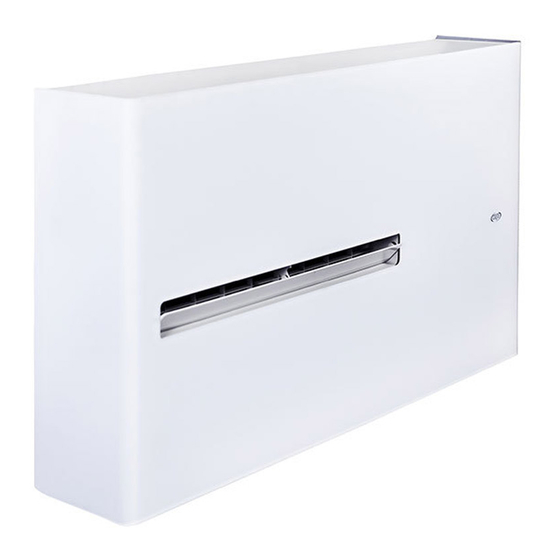
Air conditioner without outdoor unit
Climatizzatore senza unità esterna
Climatiseur sans unité extérieure
Klimagerät ohne Ausseneinheit
Acondicionador de aire sin unidad exterior
Ar condicionado sem unidade externa
37.4255.175.00
06/2018
INSTALLATION
EN
INSTRUCTIONS
MANUALE
D'INSTALLAZIONE
NOTICE
FR
D'INSTALLATION
INSTALLATIONS-
DE
ANLEITUNGEN
INSTRUCCIONES
ES
DE INSTALACIÓN
INSTRUÇÕES DE
PT
INSTALAÇÃO
IT
Advertisement

Related Manuals for Argo DD


Summary of Contents for Argo DD
- Page 1 INSTALLATION INSTRUCTIONS MANUALE D’INSTALLAZIONE NOTICE D’INSTALLATION INSTALLATIONS- ANLEITUNGEN INSTRUCCIONES DE INSTALACIÓN INSTRUÇÕES DE INSTALAÇÃO Air conditioner without outdoor unit Climatizzatore senza unità esterna Climatiseur sans unité extérieure Klimagerät ohne Ausseneinheit Acondicionador de aire sin unidad exterior Ar condicionado sem unidade externa 37.4255.175.00 06/2018...
-
Page 2: Table Of Contents
DECLARATION OF CONFORMITY This product is marked as it satisfies Directives: – LVD no. 2014/35/EU (Standard: EN60335-2-40:2003 (incl. Corr.:2006) + A11:2004 + A12:2005 + A13:2012 + A1:2006 + A2:2009 with EN 60335-1:2012 (incl. Corr.:2014) + A11:2014). – EMC no. 2014/30/EU (Standard: EN 55014-1:2006 + A1:2009 + A2:2011; EN 55014-2:1997 + A1:2001 + A2:2008; EN 61000-3-2:2014; EN 61000-3-3:2013). – RoHS2 n.2011/65/EU + 2015/863/EU amending ANNEx II. This declaration will become void in case of misuse and/or non-observance though partial of manufacturer’s installation and/or operating instructions. -
Page 3: Generalities
• Supply the unit with a dedicated electrical line. • Make install the unit by qualified personnel. • Before installation, check that the voltage of the electric supply in your home or office is the same as the voltage shown on the nameplate. • The installation of a double-pole switch, protected by 10 A fuses of the delayed type, upstream the electricity wall socket, is recommended. • Make sure that circuit breakers, fuses, etc, are of sufficient capacity to handle a start-up current of 20 A (generally less then 1 second) - ONLY FOR ON/FF VERSION • WARNING! The air conditioner is provided with a time-guard system, which does not allow re-starting of compressor until after 3 minutes from a previous stop. -
Page 4: Presentation
2 - PRESENTATION 2.1 - DESCRIPTION OF THE PARTS 1. Wireless remote control unit 2. Signaling lamps an d receiver 3. Supply air deflector 4. Bottom air intake grille (removable) 5. Air filter 6. Electric cable with plug 7. Air inlet hole with fan 8. - Page 5 2.2 - SIGNALING LAMPS WARNING The OFF position does not disconnect the power. Use the main power switch to turn off power completely. NOTES It is possible to set the air conditioner in order to let the OPERATION, TIMER and STANDBY lamps always OFF, even during operation.
-
Page 6: Installation
2.4 - DIMENSIONS AND WEIGHT Model Weight (kg) DD DCI 3 - INSTALLATION 3.1 - INSTALLATION SITE SELECTION IMPORTANT NOTES AVOID • The wall must be a perimeter one. • Proximity to heat sources, exhaust fans. • Select a sufficiently strong wall to support the weight of • Proximity to combustible materials. the unit. • Direct sunlight. • Fix the unit at a minimum height of 30 cm. • Locations where the unit could be splashed with water • Leave a minimum operation and maintenance area or affected by dampness or humidity (i.e. - Page 7 CAUTION After the selection of the installation site, according to the above mentioned points, be sure not to make Level holes in areas where electrical wiring or conduits are located, damaging them. Full scale Make sure that there are no obstacles in the conduits diagram inside the wall affecting the free circulation of the external air.
- Page 8 - Insert in the two holes the obtained plastic tubes. - Fix the two anti-intrusion grilles and the two external grilles with the blades toward the bottom using wall rawl OUTSIDE INSIDE plugs and screws. - In case it is not possible to fix the two external grilles directly at the wall, hook the two grilles to the internal ones (3) using the supplied tension bars, as follows: a) Bend them, fix the hook of the spring, insert them inside the tube and open them toward the outside.
- Page 9 WARNING! The supplied plastic sheet can be used for wall Plastic tubes ø 160mm thickness up to 50 cm; in special cases (i.e. installations Insulation in a garret) it can be necessary to utilise longer tubes. The maximum allowable length is 2 m. You can go to any building material retailer, buy the plastic tube of the same diameter (ø160 mm), of the proper length and cover it outside with insulating material (thickness: about 3-4 cm). - Fix the hanging bracket to the wall in the position indicated on the full scale diagram.
- Page 10 ON/OFF CONTACT CONNECTION The air conditioner is equipped with an ON / OFF contact (in very low voltage, to be connected to a clean contact, not in tension); When opening the contact, the air conditioner is in stand-by. Through this contact it is possible to connect an external device that inhibits the operation of the air conditioner, as for example: window opening contact, remote on / off, infrared presence sensor, enabling badge, etc. It is recommended to use a double insulation cable. The unit is supplied with a pre-installed jumper between 2 poles of the terminal block; remove the jumper before connecting the remote ON / OFF contact.
-
Page 11: Match Between Remote Controller And Unit
4 - MATCH BETWEEN REMOTE CONTROLLER AND UNIT If there are more units installed in the same room, it is possible to combine each remote controller with a unit in order to avoid interference, by operating as follows: • Disconnect the power of the unit. • Remove the batteries from the remote control unit. -
Page 12: Special Settings
5 - SPECIAL SETTINGS SPECIAL SETTINGS THROUGH JUMPER JP1: Internal use. Do not change factory setting. JP2 / JP3: Description Open Open Normal operation (factory setting) Closed Open Setting “cooling only”. If the heating mode is selected, the “wrong mode” error will be generated (see auto-diagnosis table). - Page 13 During the heating mode, the air conditioner will now operate with the new calibration of the air probe. Nota: this setting has no effect when I Feel is selected. In this case the air conditioner will operate with the remote control air probe.
-
Page 14: Electrical Wiring Diagrams
5 - ELECTRICAL WIRING DIAGRAMS - SCHEMI ELETTRICI - SCHÉMAS ÉLECTRIQUES - ELEKTRISCHE ANSCHLUSSPLÄNE - ESQUEMAS ELÉCTRICOS... - Page 16 Via Alfeno Varo, 35 - 25020 Alfianello - BS - Italy Tel. +39 0331 755111 - Fax +39 0331 755501 www.argoclima.com...
Need help?
Do you have a question about the DD and is the answer not in the manual?
Questions and answers