Table of Contents
Advertisement
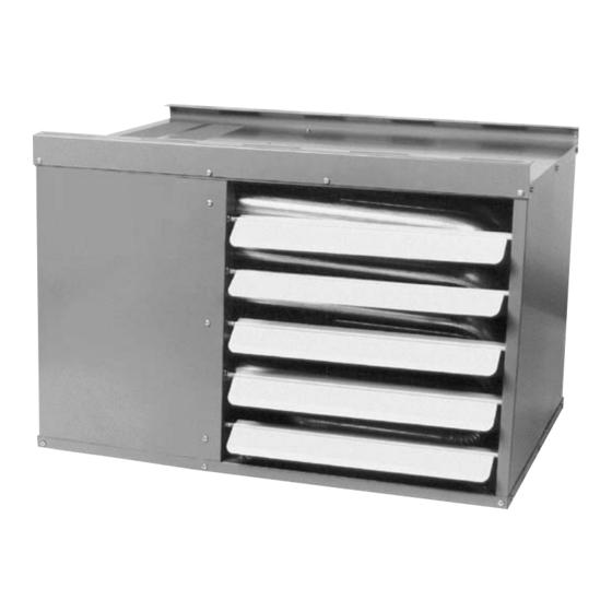
TUBULAR GAS FIRED DIRECT SPARK PROPELLER UNIT HEATERS
ATTENTION: READ THIS MANUAL AND ALL LABELS ATTACHED TO THE UNIT CAREFULLY BEFORE
ATTEMPTING TO INSTALL, OPERATE OR SERVICE THESE UNITS! CHECK UNIT DATA PLATE FOR TYPE OF GAS AND
ELECTRICAL SPECIFICATIONS AND MAKE CERTAIN THAT THESE AGREE WITH THOSE AT THE POINT OF INSTALLATION.
RECORD THE UNIT MODEL AND SERIAL No.(s) IN THE SPACE PROVIDED. RETAIN FOR FUTURE REFERENCE.
Model No.
Do not store or use gasoline or other flammable vapors and liquids in the vicinity of this or
any other appliance.
cause property damage, injury, or death. Read the installation, operating, and
maintenance instruction thoroughly before installing or servicing this equipment.
instructions to avoid exposure to fuel substances, or substances from incomplete combustion,
which can cause death or serious illness. The state of California has determined that these
substances may cause cancer, birth defects, or other reproductive harm.
Installer Please Note: This equipment has been test fired and inspected. It has been
shipped free from defects from our factory. However, shipment and installation
problems such as loose wires, leaks, or loose fasteners may occur. It is the installer's
responsibility to inspect and correct any problem that may be found.
RECEIVING INSTRUCTIONS
Inspect shipment immediately when
received to determine if any damage has
occurred to the unit during shipment. After
the unit has been uncrated, check for any
visible damage to the unit. If any damage
is found, the consignee should sign the bill
of lading indicating such damage and
immediately file claim for damage with the
transportation company.
10/05
INSTALLATION INSTRUCTIONS AND PARTS LIST
– FOR RESIDENTIAL INSTALLATIONS –
WHAT TO DO IF YOU SMELL GAS
Do not try to light any appliance.
Do not touch any electrical switch; do
not use any phone in your building.
Immediately call your gas supplier
from a neighbor's phone. Follow the
gas supplier's instructions.
If you cannot reach your gas supplier,
call your fire department.
Improper installation, adjustment, alteration, service, or maintenance can
APPROVED FOR USE IN CALIFORNIA
Install, operate, and maintain unit in accordance with the manufacturer's
INSTALLER'S RESPONSIBILITY
Serial No.
FOR YOUR SAFETY
FOR YOUR SAFETY
260 NORTH ELM ST., WESTFIELD, MA 01085
TEL: (413) 564-5540
www.sterlinghvac.com
Please utilize this toll free number to contact your local
representative 800-490-2290.
HVAC PRODUCTS
FAX: (413) 562-5311
MODELS: RF-30, 45, 60, 75, 90
(S) DSLPRFM-1
J30-06933 Rev. A
Advertisement
Table of Contents

Related Manuals for Sterling RF-30


Summary of Contents for Sterling RF-30
- Page 1 INSTALLER'S RESPONSIBILITY Please utilize this toll free number to contact your local representative 800-490-2290. HVAC PRODUCTS 260 NORTH ELM ST., WESTFIELD, MA 01085 TEL: (413) 564-5540 FAX: (413) 562-5311 www.sterlinghvac.com MODELS: RF-30, 45, 60, 75, 90 (S) DSLPRFM-1 J30-06933 Rev. A...
-
Page 2: Table Of Contents
SPECIFICATIONS Basic Description ... 2 Performance & Specification Data ... 4 GENERAL SAFETY INFORMATION Installation Codes ... 2, 3 Special Precautions ... 2, 3 INSTALLATION Locating Units ... 5, 6 Combustion Air ... 5, 6 Proper Clearances ... 5, 6 Suspension of Units ... -
Page 3: General Safety Information
GENERAL SAFETY INFORMATION Failure to comply with the general safety information may result in extensive property damage, severe personal injury, or death. This product must be installed by a licensed plumber or gas fitter when installed within the Commonwealth of Massachusetts. Installation must be made in accordance with local codes, or in absence of local codes, with the latest edition of ANSI Standard Z223.1 (N.F.P.A. - Page 4 Table 1 - Performance and Dimensional Data - Tubular 30 thru 90 Propeller Unit Heater Unit Size PERFORMANCE DATA† Input - BTU/Hr. (kW) Output - BTU/Hr. (kW) Thermal Efficiency (%) Free Air Delivery - CFM (cu. m/s) Air Temperature Rise - Deg. F (Deg.
-
Page 5: Installation
Do not install unit heaters in corrosive or flammable atmospheres! Premature failure of, or severe damage to the unit will result! Avoid locations where extreme drafts can affect burner operation. Unit heaters must not be installed in locations where air for combustion would contain chlorinated, halogenated or acidic vapors. -
Page 6: Installation Codes
The Unit Heater may be mounted by fastening the hanging brackets directly to ceiling joists or by suspending from four rods. See Figures 3, 4 and 5. Make certain that the lifting methods used to lift the heater and the method of suspen- sion used in the field installation of the heater are capable of uniformly supporting the weight... -
Page 7: Pipe Sizing
To avoid damage or possible personal injury, do not connect gas piping to this unit until a supply line pressure/leak test has been completed. Connecting the unit before completing the pressure/leak test may damage the unit gas valve and result in a fire hazard. Do not rely on a shut-off valve to isolate the unit while conducting gas pressure/leak tests. -
Page 8: Pipe Installation
1. Install the gas piping in accordance with applicable local codes. 2. Check gas supply pressure. Each unit heater must be connected to a gas supply capable of supplying its full rated capacity as specified in Table 3. A field LP tank regulator must be used to limit the supply pressure to a maximum of 14 in. -
Page 9: Electrical Connections
ELECTRICAL CONNECTIONS HAZARDOUS VOLTAGE! DISCONNECT ALL ELECTRIC POWER INCLUDING REMOTE DISCONNECTS BEFORE SERVICING. Failure to disconnect power before servicing can cause severe personal injury or death. Standard units are shipped for use on 115 volt, 60 hertz, single phase electric power. The motor name-plate and electrical rating of the transformer should be checked before energizing the unit heater electrical system. - Page 10 ELECTRICAL CONNECTIONS (continued) Figure 9 - Tubular Propeller Units Equipped with a Rollout Switch Tubular 30 thru 90 Unit Sizes with Natural and Propane (LP) Gas NOTICE: See Figures 7, 8 and 9 for connecting the thermostat to the unit heater.
-
Page 11: Venting
All unit heaters must be vented! All Venting installations shall be in accordance with the latest edition of Part 7, Venting of Equipment of the National Fuel Gas Code, ANSI Z223.1, or applicable provisions of local building codes. Refer to notes* below for Canadian installations. Refer to Figures 12-19. CARBON MONOXIDE! Your venting system must not be blocked by any snow, snow drifts, or any foreign matter. - Page 12 ANSI now organizes vented appliances into four categories. Venting Categories Condensing Condensing Negative Vent Pressure Positive Vent Pressure VERTICALLY VENTED UNIT HEATERS Observe the following precautions when venting the unit: The unit heater shall be connected to a factory built chimney or vent complying with a recognized standard, or a masonry or concrete chimney lined with a lining material acceptable to the authority having jurisdiction.
- Page 13 HORIZONTALLY VENTED UNIT HEATERS (CATEGORY I - U.S. RESIDENTIAL ONLY) All venting of residential tubular unit heaters must comply with CSA International Requirement 10.96 U.S. for Unit Heaters for Residential Use (2 Category I horizontal venting arrangements are designed to be used with either single wall vent pipe or double wall (Type B) vent pipe.
- Page 14 Table 4 - Category I Horizontal Venting Requirements Vent Unit Diameter Size (in) * One elbow is required to make the vertical extension, See Figure 13. Figure 13 - Category I Horizontal Venting Requirements Maximum Number Maximum Horizontal Elbows Vent Length (Ft.) D-06838A Minimum...
- Page 15 Figure 14 - Vent Support D- 06839A...
- Page 16 HORIZONTALLY VENTED UNIT HEATERS All venting of residential tubular unit heaters must comply with the latest edition of CSA .10.96 (2 ed.) requirement. Category III horizontal venting arrangements are designed to use single wall vent pipe. These arrange- ments must terminate external to the building using either single wall or double wall (Type B) vent.
- Page 17 Figure 15 - Category III Horizontal Venting Requirements Using Single Wall Vent Pipe Figure 15A - Category III Horizontal Venting Requirements Using Type B Double Wall Vent Pipe Figure 15B - Type B Draft Hood Connector...
- Page 18 VENTING (continued) Figure 16 Figure 17...
- Page 19 VENTING (continued) Figure 18 Figure 19...
-
Page 20: Operation
POWER VENTED PROPELLER UNITS EXPLANATION OF CONTROLS (See Figure 20): 1. Each Unit Heater comes equipped with a power vent system that consists of a power venter motor and blower, pressure switch, and sealed flue collector in place of the conventional draft diverter. 2. -
Page 21: Gas Input Rate
PRIMARY AIR SHUTTER ADJUSTMENT Primary air adjustment is made at the factory. No field adjustments are necessary. Check the gas input rate as follows (Refer to General Safety Information section for metric conversions). Never overfire the unit heater, as this may cause unsatisfactory operation, or shorten the life of the heater. -
Page 22: Periodic Service
NATURAL GAS *Heating Manifold Altitude Value Pressure (Feet) BTU/Cu. ft. (In. W.C.) 2,000 2,500 3,000 3,500 4,000 4,500 5,000 5,500 6,000 *Notes: 1. Consult local utility for actual heating value. 2. Tables based on heating value of 1,050 BTU/Cu. ft. at sea level. PERIODIC SERVICE NOTICE: The heater and vent system should be checked once a year by a qualified technician. - Page 23 Table 7 - Tubular Propeller Troubleshooting Guide SYMPTOMS A. Flame pops back. 1. Burner orifice too small. B. Noisy Flame. 1. Irregular orifice causing whistle or resonance. 2. Excessive gas input. C. Yellow tip flame (some yellow 1. Clogged main burners. tipping on LP gas is permissible).
- Page 24 Table 7 - Tubular Propeller Troubleshooting Guide (continued) SYMPTOMS I. Burners will not shut off. 1. Thermostat located incorrectly. 2. Improper thermostat wiring. 3. Shorted circuit. 4. Defective sticking gas valve. 5. Excessive gas supply pressure. J. Rapid burner cycling. 1.
- Page 25 Table 7 - Tubular Propeller Troubleshooting Guide SYMPTOMS Q. Cold air is delivered during 1. Incorrect manifold pressure or input. heater operation. 2. Air throughput too high. R. High limit tripping. 1. Unit is over fired. 2. Air flow is low. 3.
- Page 26 Table 8 - Troubleshooting with LED Indicator Assistance No Cycling or appliance power LED STATUS or thermostat call for heat Slow Flash since appliance failure has occured. Fast Flash Steady Off Line voltage power can cause product damage, severe injury or death. Only a trained experienced Steady On service technician should...
-
Page 27: Identification Of Parts
IDENTIFICATION OF PARTS RESIDENTIAL TUBULAR 30-90 MBH UNIT SIZES Item ItemDescription Vestible Panel/Tube Ass’y (Heat Exchanger) Manifold Bracket Sub-Ass’y Manifold Inshot Burner *Standard Orifice Natural Gas or Propane (LP) Gas Spark Ignitor Flame Sensor Gas Valve, Single Stage Natural or Propane (LP) Gas Manual Rollout Safety Switch Transformer, 50 VA, 115/24 Air Pressure Switch... -
Page 28: Identification Of Parts
RESIDENTIAL TUBULAR 30-90 MBH UNIT SIZES Figure 21 - Propeller Parts Fan Blade Fan Guard Motor Hardware NOTE: No rubber grommets are equipped with the 30 and 45 unit sizes. Figure 23 - Internal Furnace Components IDENTIFICATION OF PARTS Figure 22 - Component Parts D4791 Hardware D4430... -
Page 29: How To Order Replacement Parts
HOW TO ORDER REPLACEMENT PARTS Please send the following information to your local representative: if further assistance is needed, contact the manufacturer's customer service department. •Model Number •Serial Number (if any) •Part Description and Number as shown in Replacement parts Catalog Residential Power Vented Tubular Propeller Unit Heaters 1. -
Page 30: Gas Equipment Start-Up
Customer ____________________________________ Job Name & Number _________________________ Type of Equip: Unit Heater Serial Number _________________________ Model Number __________________________ Name Plate Voltage: _____________ Type of Gas: Natural ❐ Are all panels, doors, vent caps in place? ❐ Has the unit suffered any external damage? ❐...
Need help?
Do you have a question about the RF-30 and is the answer not in the manual?
Questions and answers