Table of Contents
Advertisement
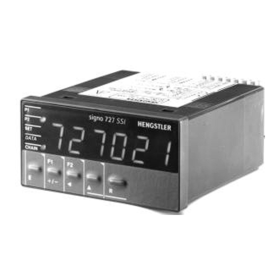
operating instructions
signo 727 SSI
Position-Indicator with/without limit
values and SSI input from absolute
encoder
1. Safety instructions
This instrument has been built and tested in
accordance with EN 61010, part1 - Protection
Measures for Electronic Measuring Instruments -
and have left our works in safe and proper condition.
In order to maintain these conditions and to ensure
safe
operation,
the
instructions
and
warnings
operating instructions.
• This units must only be operated if correctly
installed!
• The supply voltage must be derived from a SELF
SOURCE (12-24VDC versions) according to EN 60
950, since no galvanic separation is provided
between power-supply and electronic in-/outputs!
• When mounting and installing the units, the
instructions of the local suppliers of energy are to
be considered.
• The unit must only be opened for setting by trained
personnel.
• The plug-in terminals, at rear of the unit, must not
be accessed before first isolating the supply.
• The identification numbers of the plug-in terminals
and of the corresponding socket strip must be
observed.
• Unassigned terminals (NC) may not be connected!
• Connection terminals are to be protected by
installation!
Seite1/7
user
must
observe
provided
in
these
Contents
3.2 Setting the reference value and resset
of the chain value
3.3 Changing limit value 1and 2 and set
• In order to ensure hand contact safety at the
connection terminals, live wires must be con-
nected properly to the connection terminals.
• If safe operation can no longer be ensured, the
the
position indicator must be disabled and secured
against accidential operation.
• Installation of electrical devices should only be
carried out by a qualified electrican.
• Panel mounting devices should only be operated
when proberly mounted in the panel
• Before switching on, make sure that the power and
control voltages do not exceed the values specified
in the technical data.
• In a situation where failure of the device could
cause harm to people, animals or property,
additional safety measures must be employed,
e.g. stop switches, protection devices etc.
• Hengstler counters are intended for industrial
applications.
• The mounting and environment and nearby cabling
have an important influence on the EMC (noise
radiation and noise immunity) of the counter.
When putting into operation, the EMC of the whole
installation (unit) has to been secured. In
particular, the relay outputs are to be protected
from high noise radiation by suitable wiring.
Sach-Nr. 2 727 022 Version 1250899MW
1
2
2
2
2
3
3
3
3
3
4
4
4
5
5
5
6
6
6
7
7
7
Advertisement
Table of Contents

Related Manuals for Hengstler signo 727 SSI


Summary of Contents for Hengstler signo 727 SSI
-
Page 1: Table Of Contents
• The unit must only be opened for setting by trained e.g. stop switches, protection devices etc. personnel. • Hengstler counters are intended for industrial • The plug-in terminals, at rear of the unit, must not applications. be accessed before first isolating the supply. -
Page 2: Mounting Of The Position Indicator
2. Mounting of the position indicator Mounting and dimensional drawing (dimensions in mm) 2.1 Mounting the position indicator into the panel. Slide installation frame towards the rear and off the position indicator, lift the two self locking catch springs. Turn back the screws of the installation frame by approx. 5 mm. Insert position indicator into the cut-out of panel and snap installation frame into place Fix the position indicator with the screws against the panel. -
Page 3: Description Of Inputs And Outputs
2.2.2 Description of in- and outputs Function Terminal Remarks: Power supply of position AC: Terminal 1-4 at 230 VAC: bridge terminals 2-3; indicator DC: Terminal 1-2 at 115 VAC: bridge terminals 1-2 and 3-4; at 12..24VDC:Terminals 3 and 4 are not connected Relay output for limit Terminal 6-8 change over contact, Remark: these terminals are not... -
Page 4: Value
3.2. Setting the reference va lue or reset of the chain value Function Procedure • Setting the absolute value to a When absolute value is dis-played: Press simultaneously the buttons R reference value • Zerosetting of the chain value When chain value is dis-played (LED CHAIN illuminated): Press R-button. •... -
Page 5: Display Of The Absolute Data Of The Absolute Shaft Encoders
4.2 Display of the absolute data of the absolute shaft encoders Function Procedure • Entering level 2 Press E and F2 simultaneously, light diode DATA is illuminated • Select absolute data Press to switch either to single turn or to multi turn data. Editing of the value is not possible. -
Page 6: Locking Of Keyboard Functions
Parameter Display Alternatives / Signification NPN/PNP selection 'F24' '0': KEYLOCK and APPL.are low active, npn switching '1':* KEYLOCK and APPL.are high active, pnp switching Set funktion key lock 'F26' if key lock input is active, setting and canceling of calibration (calibration) '0':* value is not locked... -
Page 7: Technical Data
Switching Voltage max 30 VDC/250 VAC; min. 5 V 7. Technical data AC/DC Mechanical Specifications Switching Current max 1 A; min 10 mA Dimensions according to DIN 43700, 96 x 48 x Relay Response Delay 15 ms 108 mm Mounting with clamping frame in a panel cut- Transistor-Output (terminals 14, 15)
Need help?
Do you have a question about the signo 727 SSI and is the answer not in the manual?
Questions and answers