Star Micronics SP298 Series User Manual
Slip printer
Hide thumbs
Also See for SP298 Series:
- Programmer's manual (79 pages) ,
- User manual (2 pages) ,
- Brochure & specs (32 pages)

Related Manuals for Star Micronics SP298 Series


Summary of Contents for Star Micronics SP298 Series
-
Page 1: Slip Printer
SLIP PRINTER SP298 SERIES USER’S MANUAL MODE D’EMPLOI BEDIENUNGSANLEITUNG MANUALE DI ISTRUZIONI... -
Page 2: Fcc Warning
Cet appareil numérique de la classe A est conforme à la norme NMB-003 du Canada. The above statement applies only to printers marketed in Canada. Trademark acknowledgments SP298, AutoSide Loading: Star Micronics Co. Ltd. ESC/POS, TM-295, TM-290: Seiko Epson Corporation Notice •... -
Page 3: Table Of Contents
TABLE OF CONTENTS Chapter 1: Printer Setup ...1 Choosing a place for the printer ...1 Unpacking the printer ...2 Removing the protective materials ...2 General guide ...3 Removing the printer cover ...4 Installing the ribbon cassette ...4 Removing the ribbon cassette ...6 Connecting to a power outlet and turning power on and off ...6 Connecting to your host computer ...8 Connecting to a peripheral unit ...10... -
Page 4: Chapter 1: Printer Setup
Chapter 1: Printer Setup This chapter contains important information on setting up your printer. Be sure to read this chapter carefully before using the printer for the first time. In this chapter you will learn about: ❏ Choosing a place for the printer ❏... -
Page 5: Unpacking The Printer
Unpacking the printer Check to make sure that the carton contains each of the items shown in the following illustration. If anything is missing, contact the dealer where you bought the printer and ask them to supply the missing part. Note that it is a good idea to keep the original box and all the packing materials just in case you need to pack the printer up again and send it somewhere at a later date. -
Page 6: General Guide
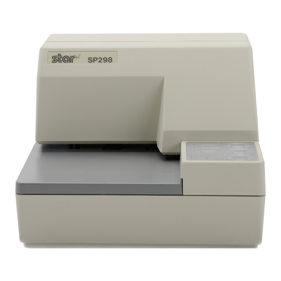
General guide The following illustrations describe the major components, buttons, and connectors of your printer. Power switch Turns printer power on and off. Peripheral unit connector cover Covers a modular jack for connection of a cash drawer or other peripheral. Do not connect a telephone line to this connector. -
Page 7: Removing The Printer Cover
Removing the printer cover ❏ Push straight up on the ridged locations on the sides of the printer cover to remove it from the printer. Printer cover ❏ To replace the cover, slide it back down into position. Gently press down on the cover until you hear it click securely into place. - Page 8 ❏ Holding the ribbon cassette so that the ribbon is facing down, install the cassette into the slip printer as shown in the illustration. ❏ Press gently but firmly on the cassette until it snaps securely into place. ❏ Rotate the knob on the cassette again to take up any slack. ❏...
-
Page 9: Removing The Ribbon Cassette
Removing the ribbon cassette Use the following procedure to remove the ribbon cassette from the slip printer when you want to replace it with a new one. ❏ Make sure that the printer is turned off and unplugged from its power outlet. - Page 10 ❏ Plug the other end of the power cord to a standard household wall outlet. ❏ Use the power switch on the left side of the printer to turn power on and off. Important! We recommend that you unplug the printer from the power outlet whenever you do not plan to use it for long periods.
-
Page 11: Connecting To Your Host Computer
Connecting to your host computer The computer sends data to the printer through a cable to the printer’s interface (Serial Interface Connector Type: D-sub 25-pin or Parallel Interface Connector Type: 36-pin Centronics compatible). This printer does not come with a cable, so it is up to you to obtain one that suits your needs. - Page 12 Pass the fastener through the ferrite core. Loop the fastener around the cable and lock it. Use scissors to cut off any excess. For a serial cable: ❏ Plug one end of the serial cable into the serial port of your computer, and the other end of the cable into the socket on the back of the printer.
-
Page 13: Connecting To A Peripheral Unit
Connecting to a peripheral unit You can connect a peripheral unit to the printer using a modular plug. The following describes how to install the ferrite core and make the actual connection. See “Modular plug” on page 137 for details about the type of modular plug that is required. -
Page 14: Inserting The Paper Into The Printer
Loop the fastener around the cable and lock it. Use scissors to cut off any excess. ❏ Plug one end of the modular cable into the modular jack of the peripheral. ❏ Remove the modular jack cover from the back of the printer and plug the other end of the modular cable into the jack of the printer. -
Page 15: Autoside Loading
❏ Place a piece of the paper onto the printer’s document table and slide its right edge into the printer. Printing will be performed on the side of the paper that is facing up (the one you can see), starting from the top of the paper. - Page 16 ❏ Push the right edge of the paper into the printer until it stops. At that time, the PAPER OUT indicator will go out, and the printer mechanism will automatically align the paper for printing from the top. ❏ Send data from your host computer to be printed on the paper. ❏...
-
Page 17: Chapter 2: Control Panel Operations
Chapter 2: Control Panel Operations The control panel gives you some push-button control over the slip printer operation. It also includes indicator lights, which tell you the current status of the printer at a glance. Indicator lights The following table describes the meaning of indicator lights when it is on, off, or flashing. -
Page 18: Buttons
Buttons The following table describes the function of the three control buttons of the control panel. Button Feeds the slip paper forward, toward the back of the printer. One FORWARD press feeds one line, holding down performs continuous feed. Feeds the slip paper back, toward the front of the printer. One press REVERSE feeds one line, holding down performs continuous feed. - Page 19 This is caused when mechanical parts of the printer get out of alignment. This happens only rarely and you may never experience it at all throughout the life of the printer. If you do have problems, use the following procedure to correct it. ❏...
-
Page 20: Hexadecimal Dump
The dots alignment adjustment setting you selected is stored in printer memory and a pattern is printed using the selected setting followed by the message “Adjust Complete!” The printer ejects the paper after printing is complete. Note: You setting is not registered if you turn off printer power before pressing REVERSE to exit the Dot Alignment Adjust Mode. -
Page 21: Errors
Errors There are three types of errors: recoverable errors that require some action by you before they clear, non-recoverable errors that require servicing by an authorized service provider, and a data receive error. Errors are indicated by and audible buzzer and the indicators. Recoverable Errors Error Type POWER... -
Page 22: Paper Sensors
Paper Sensors The following paper sensors are available. ❏ TOF Sensor This top-of-form sensor detects the leading edge of the paper. When enabled, the TOF sensor detects when there is no paper present and stops printing. ❏ BOF Sensor This bottom-of-form sensor detects the trailing edge of the paper. When enabled, the BOF sensor detects when there is no paper present and printing is interrupted. -
Page 23: Chapter 3: Command Summary
Chapter 3: Command Summary This printer supports two different command modes: the Star mode and the ESC/POS mode. The Star mode emulates previous Star printers. The ESC/POS mode emulates the Epson TM-295 or TM-290 slip printer. This chapter provides you with all of the commands supported by this printer. Important! Access the following URL for the latest version of this manual and for updates on supported commands: http://www.star-micronics.co.jp/service/... - Page 24 Control Codes <ESC> “W” n 1B 57 n <ESC> “h” n 1B 68 n <ESC> “–” “1” 1B 2D 31 <ESC> “–” <1> 1B 2D 01 <ESC> “–” “0” 1B 2D 30 <ESC> “–” <0> 1B 2D 00 <ESC> “_” “1” 1B 5F 31 <ESC>...
-
Page 25: Print Position Control
Print Position Control Control Codes <LF> <CR> <ESC> “a” n 1B 61 n <HT> <ESC> “A” n 1B 41 n <ESC> “2” 1B 32 <ESC> “z” “0” 1B 7A 30 <ESC> “z” <0> 1B 7A 00 <ESC> “z” “1” 1B 7A 31 <ESC>... -
Page 26: Dot Graphics Control
Dot Graphics Control Control Codes <ESC> “K” n <0> 1B 4B n 00 m1 m2 m1 m2 ... <ESC> “L” n1 n2 1B 4C n1 n2 m1 m2 m1 m2 ... Download Graphics Printing Control Codes <ESC> “&” <0> n1 n2 .. 1B 26 00 n1 n2 .. -
Page 27: Page Mode
Slip Control Control Codes <ESC> <SI> n 1B 0F n <ESC> <FF> n 1B 0C n <ESC> <VT> m n 1B 0B m n <ESC><EM>mn<LF><NUL> 1B 19 n m 0A 00 Page mode Control Codes <ESC> “n” 1B 6E <ESC> “!” 1B 21 <ESC>... - Page 28 Control Codes <ESC><ACK><SOH> IB 06 01 <ESC><RS> “a” n IB IE 61 n <ESC> “?” <LF> <NUL> 1B 3F 0A 00 Hexadecimal Codes Transmits automatic status Enables/disables automatic status Resets printer hardware and produce a test print Function...
-
Page 29: Esc/Pos Mode Commands (Tm-295 Emulation)
ESC/POS Mode Commands (TM-295 emulation) The following table lists the TM-295 emulation commands that are supported by this printer. Control Codes <HT> <LF> <FF> <DLE> <EOT> 10 04 <CAN> <ESC> SP 1B 20 <ESC> ! 1B 21 <ESC># 1B 23 <ESC>... - Page 30 Control Codes <ESC> L 1B 4C <ESC> R 1B 52 <ESC> T 1B 54 <ESC> U 1B 55 <ESC> V 1B 56 <ESC> W 1B 57 <ESC> a 1B 61 <ESC> c3 1B 63 33 <ESC> c4 1B 63 34 <ESC>...
-
Page 31: Esc/Pos Mode Commands (Tm-290 Emulation)
ESC/POS Mode Commands (TM-290 emulation) The following table lists the TM-290 emulation commands that are supported by this printer. Control Codes <HT> <LF> <FF> <ESC> SP 1B 20 <ESC> ! 1B 21 <ESC># 1B 23 <ESC> * 1B 2A <ESC> 2 1B 32 <ESC>... - Page 32 Control Codes <ESC> R 1B 52 <ESC> c3 1B 63 33 <ESC> c4 1B 63 34 <ESC> c5 1B 63 35 <ESC> d 1B 64 <ESC> h 1B 68 <ESC> j 1B 6A <ESC> q 1B 71 <ESC> t 1B 74 <ESC>...
- Page 33 TABLE DES MATIÈRES Chapitre 1: Configuration de l’imprimante...31 Emplacement de l’imprimante...31 Déballage de l’imprimante...32 Retrait des matériaux de protection ...32 Description générale ...33 Ouverture du capot...34 Installation de la cassette à ruban ...34 Retrait de la cassette à ruban...36 Raccordement à une prise secteur et mise sous et hors tension...36 Connexion à...
-
Page 34: Chapitre 1: Configuration De L'imprimante
Chapitre 1: Configuration de l’imprimante Ce chapitre vous fournira des informations importantes vous permettant de configurer votre imprimante. Veuillez lire attentivement ce chapitre avant d’utiliser l’imprimante pour la première fois. Vous y trouverez des informations qui vous aideront à : ❏... -
Page 35: Déballage De L'imprimante
Déballage de l’imprimante Contrôlez si la caisse contient bien tous les éléments illustrés ci-dessous. Si l’un des éléments mentionnés ci-dessus ne se trouve pas dans la caisse, adressez-vous au magasin où vous avez acheté l’imprimante et demandez que la pièce manquante vous soit fournie. Il est préférable de conserver la caisse d’origine ainsi que tous les emballages. -
Page 36: Description Générale
Description générale Les illustrations ci-dessous vous indiquent les principaux éléments, touches et connecteurs de l’imprimante. Interrupteur d’alimentation Cet interrupteur vous permet de mettre l’imprimante sous tension et hors tension. Cache de pilotage d’appareil périphérique Il recouvre une pris modulaire qui vous permet de raccorder un appareil périphérique, tel qu’un tiroir-caisse, etc. -
Page 37: Ouverture Du Capot
Ouverture du capot ❏ Appuyez droit sur les sections cannelées des deux côtés du capot pour le détacher de l’imprimante. Capot ❏ Pour remettre le capot en place, glissez-le en place et rabaissez-le. Appuyez délicatement sur le capot jusqu’à ce qu’il se verrouille dans un déclic. Installation de la cassette à... - Page 38 ❏ Saisissez la cassette à ruban de sorte que le ruban soit orienté vers le bas et installez-la dans l’imprimante à papier fort de la manière illustrée. ❏ Appuyez sans forcer sur la cassette de sorte qu’elle soit correctement verrouillée. ❏...
-
Page 39: Retrait De La Cassette À Ruban
Retrait de la cassette à ruban Suivez les instructions ci-dessous lorsque vous souhaitez retirer la cassette à ruban afin de la remplacer. ❏ Assurez-vous que l’imprimante est hors tension et qu’elle est débranchée de la prise secteur. ❏ Retirez le capot de l’imprimante. ❏... - Page 40 ❏ Raccordez l’autre bout du cordon d’alimentation à une prise secteur de tension appropriée. ❏ Mettez l’imprimante sous et hors tension à l’aide de l’interrupteur d’alimentation situé sur le côté gauche de l’imprimante. Attention! Nous vous recommandons de débrancher l’imprimante du secteur lorsque vous ne comptez pas l’utiliser pendant une période prolongée.
-
Page 41: Connexion À Votre Ordinateur-Hôte
Connexion à votre ordinateur-hôte L’ordinateur communique les données à l’imprimante via le câble connecté à l’interface de l’imprimante (type de connecteur d’interface série : D-Sub à 25 broches ou type de connecteur d’interface parallèle : compatible Centronics à 36 broches). Ce câble n’est pas fourni avec l’imprimante. Vous devrez donc vous en procurer un. - Page 42 Passez l’attache dans le tore de ferrite. Passez l’attache autour du tore de ferrite et serrez-la. Coupez l’extrémité de l’attache à l’aide de ciseaux. Pour un câble série: ❏ Raccordez l’une des extrémités du câble en série au port d’interface en série de votre ordinateur, et l’autre extrémité...
-
Page 43: Raccordement D'un Appareil Périphérique
Raccordement d’un appareil périphérique Vous pouvez raccorder un appareil périphérique à l’imprimante à l’aide d’une fiche modulaire. Nous expliquons ci-dessous comment installer le tore de ferrite et faire le raccordement proprement dit. Pour les détails sur le type de fiche modulaire à... -
Page 44: Introduction Du Papier Dans L'imprimante
Passez l’attache autour du tore de ferrite et serrez-la. Coupez l’extrémité de l’attache à l’aide de ciseaux. ❏ Raccordez une extrémité du câble modulaire à la prise modulaire du périphérique. ❏ Retirez le cache de prise modulaire au dos de l’imprimante, et raccordez l’autre extrémité... -
Page 45: Autoside Loading
❏ Placez une feuille de papier dans le bac à papier de l’imprimante et faites glisser son bord droit vers l’imprimante. L’impression se fera sur la face du papier tournée vers le haut (celle que l’on peut voir), à partir du haut du papier. - Page 46 ❏ Poussez le bord droit du papier dans l’imprimante jusqu’à ce qu’il soit stoppé. A ce stade, le voyant d’absence de papier PAPER OUT s’éteint et le mécanisme de l’imprimante aligne automatiquement le papier pour commencer l’impression dans le haut de la feuille. ❏...
-
Page 47: Chapitre 2: Tableau De Commande
Chapitre 2: Tableau de commande Le panneau de commandes permet de contrôler le fonctionnement de l’imprimante de papier fort par boutons poussoir. Il contient également des témoins lumineux qui vous indiquent l’état de l’imprimante en un simple coup d’œil. Témoins lumineux Le tableau ci-dessous vous explique l’état de l’imprimante pour chaque témoin allumé, éteint ou clignotant. -
Page 48: Touches
Touches Le tableau ci-dessous vous explique la fonction des trois touches du tableau de commande. Touche Alimente le papier fort vers l’avant, vers le dos de l’imprimante. Une FORWARD pression fait avancer le papier d’une ligne, une pression continue produit une avance continue. Alimente le papier fort vers l’arrière, vers l’avant de l’imprimante. - Page 49 Ce problème est causé par un décalage des pièces mécaniques de l’imprimante. Ce problème est relativement rare et il est possible que vous ne le rencontriez jamais. Si toutefois vous rencontrez ce problème, suivez les instructions ci- dessous afin de le corriger. ❏...
-
Page 50: Vidage Hexadécimal
Le réglage d’alignement des points que vous avez sélectionné est sauvegardé dans la mémoire, et l’imprimante imprime une série de lignes graduées correspondant à l’état d’impression sélectionné, suivie du message “Adjust Completed!”, vous indiquant que le réglage est terminé. L’imprimante éjecte ensuite le morceau de papier fort. -
Page 51: Erreurs
Erreurs Vous pouvez rencontrer trois types d’erreur : les erreurs corrigibles, que vous pouvez corriger en effectuant certaines opérations, les erreurs non corrigibles, dont la correction nécessite l’intervention d’un revendeur agréé, et l’erreur de réception des données. Les erreurs sont signalées par un avertisseur sonore et par des témoins. - Page 52 Capteurs de papier Les capteurs de papier suivants sont prévus. ❏ Capteur TOF Ce capteur haut-de-page détecte le bord d’attaque du papier. Lorsqu’il est validé, le capteur TOF détecte l’absence de papier et il arrête l’impression. ❏ Capteur BOF Ce capteur bas-de-page détecte le bord arrière du papier. Lorsqu’il est validé, le capteur BOF détecte l’absence de papier et l’impression est interrompue.
-
Page 53: Chapitre 3: Résumé Des Commandes
Chapitre 3: Résumé des commandes L’imprimante supporte deux modes de commande différents : le mode STAR, et le mode ESC/POS. Le mode Star émule les imprimantes Star précédentes. Le mode ESC/POS émule l'imprimante de bordereaux TM-295 ou TM-290 Epson. Ce chapitre donne la liste de toutes les commandes supportées par l’imprimante. Attention! Pour obtenir la dernière version de ce manuel et pour les mises à... - Page 54 Code de contrôle Code hexadécimal <ESC> “W” n 1B 57 n <ESC> “h” n 1B 68 n <ESC> “–” “1” 1B 2D 31 <ESC> “–” <1> 1B 2D 01 <ESC> “–” “0” 1B 2D 30 <ESC> “–” <0> 1B 2D 00 <ESC>...
- Page 55 Commandes de position d’impression Code de contrôle Code hexadécimal <LF> <CR> <ESC> “a” n 1B 61 n <HT> <ESC> “A” n 1B 41 n <ESC> “2” 1B 32 <ESC> “z” “0” 1B 7A 30 <ESC> “z” <0> 1B 7A 00 <ESC>...
- Page 56 Commandes de graphiques en points Code de contrôle Code hexadécimal <ESC> “K” n <0> m1 m2 ... 1B 4B n 00 m1 m2... 1B 4C n1 n2 m1 <ESC> “L” n1 n2 m1 m2... m2... Impression de graphiques téléchargés Code de contrôle Code hexadécimal <ESC>...
-
Page 57: Autres Commandes
Mode de page Code de contrôle Code hexadécimal <ESC> “n” 1B 6E <ESC> “!” 1B 21 <ESC> “*” ... 1B 2A ... <ESC> “T” n 1B 54 n <FF> Autres commandes Code de contrôle Code hexadécimal <CAN> <DC3> <DC1> <RS> 1B 23 N 2C n1 n2 <ESC>... -
Page 58: Commandes Du Mode Esc/Pos (Émulation De La Tm-295)
Commandes du mode ESC/POS (Émulation de la TM-295) Le tableau ci-dessous donne la liste des commandes d'émulation de la TM-295 qui sont supportées par l'imprimante. Code de contrôle Code hexadécimal <HT> <LF> <FF> <DLE> <EOT> 10 04 <CAN> <ESC> SP 1B 20 <ESC>... - Page 59 Code de contrôle Code hexadécimal <ESC> L 1B 4C <ESC> R 1B 52 <ESC> T 1B 54 <ESC> U 1B 55 <ESC> V 1B 56 <ESC> W 1B 57 <ESC> a 1B 61 <ESC> c3 1B 63 33 <ESC> c4 1B 63 34 <ESC>...
-
Page 60: Commandes Du Mode Esc/Pos (Émulation De La Tm-290)
Commandes du mode ESC/POS (Émulation de la TM-290) Le tableau ci-dessous donne la liste des commandes d'émulation de la TM-290 qui sont supportées par l'imprimante. Code de contrôle Code hexadécimal <HT> <LF> <FF> <ESC> SP 1B 20 <ESC> ! 1B 21 <ESC>... - Page 61 Code de contrôle Code hexadécimal <ESC> R 1B 52 <ESC> c3 1B 63 33 <ESC> c4 1B 63 34 <ESC> c5 1B 63 35 <ESC> d 1B 64 <ESC> h 1B 68 <ESC> j 1B 6A <ESC> q 1B 71 <ESC>...
- Page 63 INHALTSVERZEICHNIS Kapitel 1: Drucker-Einrichtung...61 Wahl eines Aufstellungsorts für den Drucker ...61 Auspacken des Druckers...62 Entfernen der Schutzmaterialien...62 Allgemeine Anleitung...63 Abnehmen der Druckerabdeckung ...64 Einsetzen der Farbbandkassette...64 Entnehmen der Farbbandkassette ...66 Anschluß an eine Netzsteckdose und Ein-/Ausschalten der Netzversorgung...66 Anschließen an den Hostcomputer ...68 Anschluß...
-
Page 64: Kapitel 1: Drucker-Einrichtung
Kapitel 1: Drucker-Einrichtung Dieses Kapitel enthält wichtige Informationen zur Vorbereitung Ihres Druckers. Bitte dieses Kapitel sorgfältig durchlesen, bevor Sie den Drucker zum ersten Mal in Betrieb nehmen. In diesem Kapitel erfahren Sie Einzelheiten über: ❏ Wahl eines Aufstellungsorts für den Drucker ❏... -
Page 65: Auspacken Des Druckers
Auspacken des Druckers Überprüfen Sie den Kartoninhalt, und vergewissern Sie sich, daß alle unten abgebildeten Teile vorhanden sind. Falls Teile fehlen, wenden Sie sich zwecks Nachlieferung bitte an den Fachhandel, bei dem das Gerät gekauft wurde. Im Hinblick auf einen eventuellen zukünftigen Transport des Druckers empfiehlt es sich, den Lieferkarton und das gesamte Verpackungsmaterial aufzubewahren. -
Page 66: Allgemeine Anleitung
Allgemeine Anleitung Die folgenden Abbildungen zeigen die Hauptbauteile des Druckers. Druckerabdeckung Schützt interne Bauteile. Netzschalter Zum Ein- und Ausschalten des Druckers. Abdeckung der Buchse für Peripheriegeräte Deckt eine Modularbuchse zum Anschluß einer Registrierkasse oder eines anderen angeschlossen Geräts ab. Hier auf keinen Fall eine Telefonleitung anschließen. -
Page 67: Abnehmen Der Druckerabdeckung
Abnehmen der Druckerabdeckung ❏ Die geriffelten Teile an den Druckerseiten gerade nach oben drücken, um die Abdeckung abzunehmen. Druckerabdeckung ❏ Zum Schließen die Abdeckung wieder nach unten aufsetzen. Vorsichtig aufdrücken, bis sie hörbar einrastet. Einsetzen der Farbbandkassette ❏ Stellen Sie sicher, daß die Papierfreigabe des Druckers aktiviert ist (das Papier wird nicht von der Papier-Zufuhrrolle festgehalten). - Page 68 ❏ Die Farbbandkassette so halten, daß das Farbband nach unten weist und die Kassette in den Drucker einsetzen, wie in der Abbildung gezeigt. ❏ Die Farbbandkassette sanft aber fest herunterdrücken, bis sie hörbar einrastet. ❏ Den Farbband-Spannknopf auf der Kassette noch einmal drehen, um das Band zu straffen.
-
Page 69: Entnehmen Der Farbbandkassette
Entnehmen der Farbbandkassette Folgendermaßen verfahren, um die Farbbandkassette zum Austausch aus dem Drucker zu nehmen. ❏ Sicherstellen, daß der Drucker ausgeschaltet und von der Betriebsstromversorgung getrennt ist. ❏ Die Druckerabdeckung abnehmen. ❏ Die Farbbandkassette wie in der Abbildung gezeigt greifen und vorsichtig aus dem Druckmechanismus ziehen. - Page 70 ❏ Den anderen Stecker des Netzkabels an eine Netzsteckdose anschließen. ❏ Den Netzschalter an der linken Seite des Druckers zum Ein- und Ausschalten verwenden. Wichtig! Wir empfehlen, den Netzstecker aus der Steckdose zu ziehen, wenn der Drucker längere Zeit lang nicht benutzt werden soll. Der Drucker sollte vorzugsweise an einem Platz aufgestellt werden, der leichten Zugang zur Netzsteckdose gewährt.
-
Page 71: Anschließen An Den Hostcomputer
Anschließen an den Hostcomputer Die Datenübertragung vom Computer zum Drucker erfolgt über ein Kabel, das an die Schnittstelle des Druckers (serieller Anschluß, Typ D-sub, 25 polig bzw. paralleler Anschluß, Typ Centronics-kompatibel, 36 polig) angeschlossen wird. Das Kabel ist im Lieferumfang dieses Druckers nicht enthalten und muß getrennt gekauft werden. - Page 72 Führen Sie den Kabelbinder durch den Ferritkern. Führen Sie den Kabelbinder um das Kabel und sperren Sie ihn. Schneiden Sie überschüssiges Band mit einer Schere ab. Für ein serielles Schnittstellenkabel: ❏ Ein Ende des Kabels an den seriellen Anschluß des Computers anschließen und das andere Ende an die Buchse an der Rückseite des Druckers an.
-
Page 73: Anschluß An Ein Peripheriegerät
Anschluß an ein Peripheriegerät Es kann ein Peripheriegerät an den Drucker mit einem Modularstecker angeschlossen werden. Im folgenden wird beschrieben, wie der Ferritkern angebracht und die Verbindung hergestellt wird. Siehe “Modularstecker” auf Seite 137 für den Typ von Modularstecker, der dazu erforderlich ist. Beachten Sie, daß... -
Page 74: Papier In Den Drucker Einlegen
Das Befestigungsband um das Kabel wickeln und sperren. Schneiden Sie überschüssiges Band mit einer Schere ab. ❏ Einen Stecker des Modularkabels in die Modularbuchse am Peripheriegerät stecken. ❏ Die Modularbuchsenabdeckung von der Rückseite des Druckers abnehmen, und den anderen Stecker des Modularkabels in die Modularbuchse am Drucker stecken. -
Page 75: Automatischer Papiereinzug (Autoside Loading™)
❏ Legen Sie ein Blatt Papier auf den Dokumententisch des Druckers und schieben Sie die rechte Ecke in den Drucker. Der Ausdruck erfolgt auf der Seite, die nach oben zeigt (die Seite, die Sie sehen können) und beginnt am oberen Rand des Blattes. Wichtig! Benutzen Sie kein verknicktes oder verwelltes Papier. - Page 76 ❏ Schieben Sie die rechte Ecke des Blattes in den Drucker, bis Sie einen Widerstand spüren. Zu diesem Zeitpunkt wird die Anzeige PAPER OUT ausgehen und der Druckermechanismus zieht das Blatt automatisch ein und richtet es an der Druckstartposition aus. ❏...
-
Page 77: Kapitel 2: Bedienfeld
Kapitel 2: Bedienfeld Das Bedienungsfeld enthält einige Tasten, mit deren Hilfe Sie den Drucker bedienen künnen. Es enthält auch einige LED-Anzeigen, die Sie über den aktuellen Status des Druckers informieren. Anzeigeleuchten Die folgende Tabelle stellt die Bedeutung des Leuchtens, Nichtleuchtens oder Blinkens der Anzeigeleuchten dar. -
Page 78: Tasten
Tasten Die folgende Tabelle stellt die Funktion der drei Steuertasten am Bedienfeld dar. Taste Drücken, um das Quittungspapier zur Rückseite des Druckers FORWARD zuzuführen. Ein Tastendruck schiebt um eine Zeile vor, Gedrückthalten schiebt kontinuierlich vor. Drücken , um das Quittungspapier zur Vorderseite des Druckers REVERSE zurückzuführen. - Page 79 Der Grund dafür ist, daß mechanische Teile des Druckers gegeneinander verschoben werden. Dies geschieht nur selten, und die meisten Anwender werden während der Lebensdauer des Druckers damit nicht konfrontiert werden. Falls aber dieses Problem auftritt, kann es auf folgende Weise behoben werden.
-
Page 80: Sedezimaler Datenausdruck
Die Einstellungen für die Punktausrichtung werden im Druckerspeicher gespeichert, und ein Muster wird mit der gewählten Einstellung ausgedruckt, gefolgt von der Meldung “Adjust Complete!”. Der Drucker gibt das Papier nach dem Druckvorgang aus. Hinweis: Wenn der Drucker ausgeschaltet wird, ohne die Taste REVERSE zum Verlassen des Punkteinstellmodus zu drücken, werden die Einstellungen nicht gespeichert. -
Page 81: Fehler
Fehler Es gibt drei Typen von Fehlern: behebbare Fehler, die zum Beheben eine Maßnahme von Seiten des Anwenders erfordern, und nicht behebbare Fehler, die Wartungsmaßnahmen durch den Kundendienst erfordern, und Datenempfangsfehler. Die Fehlertypen werden durch ein Tonsignal und die Anzeigen dargestellt. Behebbare Fehler Fehlertyp POWER... - Page 82 Papiersensoren Die folgenden Papiersensoren stehen zur Verfügung. ❏ TOF-Sensor Dieser Vorderkantensensor (“top of form”) erkennt die Papiervorderkante. Wenn er aktiviert ist, erkennt der TOF-Sensor, daß kein Papier vorhanden ist und stoppt den Druckvorgang. ❏ BOF-Sensor Dieser Hinterkantensensor (“bottom of form”) erkennt die Hinterkante des Papiers.
-
Page 83: Kapitel 3: Zusammenfassung Der Befehle
Kapitel 3: Zusammenfassung der Befehle Dieser Drucker unterstützt zwei verschiedene Befehlsmodi: den Star-Modus und den ESC/POS-Modus, Der Star-Modus emuliert den Befehlssatz der Star-Drucker. Der Modus ESC/ POS emuliert den Epson TM295 oder TM-290 Quittungsdrucker. In diesem Kapitel werden alle von diesem Drucker unterstützten Befehle aufgeführt. - Page 84 Steuerbefehle Sedezimal-Codes <ESC> “W” n 1B 57 n <ESC> “h” n 1B 68 n <ESC> “–” “1” 1B 2D 31 <ESC> “–” <1> 1B 2D 01 <ESC> “–” “0” 1B 2D 30 <ESC> “–” <0> 1B 2D 00 <ESC> “_” “1” 1B 5F 31 <ESC>...
- Page 85 Ändern der Druckposition Steuerbefehle Sedezimal-Codes <LF> <CR> <ESC> “a” n 1B 61 n <HT> <ESC> “A” n 1B 41 n <ESC> “2” 1B 32 <ESC> “z” “0” 1B 7A 30 <ESC> “z” <0> 1B 7A 00 <ESC> “z” “1” 1B 7A 31 <ESC>...
- Page 86 Druck von Rastergrafiken Steuerbefehle Sedezimal-Codes 1B 4B n 00 m1 m2 <ESC> “K” n <0> m1 m2 ... 1B 4C n1 n2 m1 m2 <ESC> “L” n1 n2 m1 m2 ... Druck von heruntergeladenen Zeichen Steuerbefehle Sedezimal-Codes <ESC> “&” <0> n1 n2 .. 1B 26 00 n1 n2 ..
- Page 87 Befehle für Seitenmodus Steuerbefehle Sedezimal-Codes <ESC> “n” 1B 6E <ESC> “!” 1B 21 <ESC> “*” ... 1B 2A ... <ESC> “T” n 1B 54 n <FF> Weitere Befehle Steuerbefehle Sedezimal-Codes <CAN> <DC3> <DC1> <RS> 1B 23 N 2C n1 n2 <ESC>...
-
Page 88: Befehle Des Esc/Pos-Modus (Tm295 Emulation)
Befehle des ESC/POS-Modus (TM-295 Emulation) Die folgende Tabelle führt die TM-295 Emulationsbefehle aus, die von diesem Drucker unterstützt werden. Steuerbefehle Sedezimal-Codes <HT> <LF> <FF> <DLE> <EOT> 10 04 <CAN> <ESC> SP 1B 20 <ESC> ! 1B 21 <ESC> # 1B 23 <ESC>... - Page 89 Steuerbefehle Sedezimal-Codes <ESC> L 1B 4C <ESC> R 1B 52 <ESC> T 1B 54 <ESC> U 1B 55 <ESC> V 1B 56 <ESC> W 1B 57 <ESC> a 1B 61 <ESC> c3 1B 63 33 <ESC> c4 1B 63 34 <ESC>...
-
Page 90: Befehle Des Esc/Pos-Modus (Tm290 Emulation)
Befehle des ESC/POS-Modus (TM-290 Emulation) Die folgende Tabelle führt die TM-290 Emulationsbefehle aus, die von diesem Drucker unterstützt werden. Steuerbefehle Sedezimal-Codes <HT> <LF> <FF> <ESC> SP 1B 20 <ESC> ! 1B 21 <ESC> # 1B 23 <ESC> * 1B 2A <ESC>... - Page 91 Steuerbefehle Sedezimal-Codes <ESC> R 1B 52 <ESC> c3 1B 63 33 <ESC> c4 1B 63 34 <ESC> c5 1B 63 35 <ESC> d 1B 64 <ESC> h 1B 68 <ESC> j 1B 6A <ESC> q 1B 71 <ESC> t 1B 74 <ESC>...
- Page 93 Capitolo 1: Preparativi...91 Scelta di un luogo per la stampante ...91 Disimballaggio della stampante...92 Rimozione del materiale protettivo...92 Guida generale ...93 Rimozione del coperchio stampante ...94 Inserimento della cassetta del nastro ...94 Rimozione della cassetta del nastro ...96 Collegamento ad una presa di corrente e accensione e spegnimento...96 Collegamento al computer ospite ...98 Collegamento ad un’unità...
-
Page 94: Capitolo 1: Preparativi
Capitolo 1: Preparativi Questo capitolo contiene informazioni importanti su come preparare la stampante. Assicurarsi di leggere attentamente questo capitolo prima di usare la stampante per la prima volta. In questo capitolo spieghiamo quanto segue: ❏ Scelta di un luogo per la stampante ❏... -
Page 95: Disimballaggio Della Stampante
Disimballaggio della stampante Controllare che lo scatolone contenga tutti gli elementi indicati nella seguente illustrazione. Se dovesse mancare qualcosa, contattare il concessionario da cui si è acquistata la stampante e richiedere la parte mancante. Notare che è consigliabile conservare lo scatolone originale e tutti i materiali di imballaggio in caso si debba reimballare e spedire la stampante in futuro. -
Page 96: Guida Generale
Guida generale Le seguenti illustrazioni descrivono le parti principali, i tasti e i connettori della stampante. Interruttore di alimentazione Per accendere e spegnere la stampante. Coperchio connettori unità periferica Copre una presa modulare per il collegamento ad un registro di cassa o altra unità... -
Page 97: Rimozione Del Coperchio Stampante
Rimozione del coperchio stampante ❏ Spingere direttamente verso l’alto sulle zigrinature sui lati del coperchio stampante per rimuoverlo dalla stampante. Coperchio della stampante ❏ Per rimettere il coperchio, abbassarlo in posizione. Premere leggermente sul coperchio fino a sentire che scatta in posizione. Inserimento della cassetta del nastro ❏... - Page 98 ❏ Tenendo la cassetta del nastro con il nastro rivolto verso il basso, inserire la cassetta nella stampante di moduli come indicato nell’illustrazione. ❏ Premere delicatamente ma con fermezza fino a che la cassetta scatta saldamente in posizione. ❏ Girare di nuovo la manopola della cassetta per eliminare allentamenti. ❏...
-
Page 99: Rimozione Della Cassetta Del Nastro
Rimozione della cassetta del nastro Usare il seguente procedimento per rimuovere la cassetta del nastro dalla stampante di moduli quando si desidera sostituirla con un’altra nuova. ❏ Assicurarsi che la stampante sia spenta e scollegata dalla presa di corrente. ❏ Rimuovere il coperchio della stampante. - Page 100 ❏ Collegare l’altro capo del cavo di alimentazione ad una presa di corrente normale. ❏ Usare l’interruttore di alimentazione sul lato sinistro della stampante per accendere e spegnere. Importante! Consigliamo di scollegare la stampante dalla presa di corrente quando si prevede di non usarla per un lungo periodo.
-
Page 101: Collegamento Al Computer Ospite
Collegamento al computer ospite Il computer invia dati alla stampante tramite un cavo collegato all’interfaccia della stampante (tipo connettore interfaccia seriale: D-sub a 25 terminali o tipo connettore interfaccia parallela: compatibile Centronics a 36 terminali). Questa stampante non è dotata di cavo, che deve essere acquistato a seconda delle esigenze di impiego. - Page 102 Far passare la fascetta di fissaggio attraverso l’anello di ferrite. Avvolgere la fascetta intorno al cavo e fissarla. Usare delle forbici per tagliare la parte in eccesso. Per un cavo seriale: ❏ Collegare un capo del cavo seriale alla porta seriale del computer e l’altro capo alla presa sul retro della stampante.
-
Page 103: Collegamento Ad Un'unità Periferica
Collegamento ad un’unità periferica Si può collegare un’unità periferica alla stampante usando una spina modulare. Di seguito descriviamo come installare l’anello di ferrite ed eseguire il collegamento. Vedere “Modulare necessario” a pagina 137 per dettagli sul tipo di spina modulare necessario. Notare che la stampante non è dotata di spina o filo modulare, che devono essere acquistati in base alle esigenze di impiego. -
Page 104: Inserimento Della Carta Nella Stampante
Avvolgere la fascetta intorno al cavo e fissarla. Usare delle forbici per tagliare la parte in eccesso. ❏ Collegare un capo del cavo modulare alla presa modulare della periferica. ❏ Rimuovere il coperchio presa modulare dal retro della stampante e collegare l’altro capo del cavo modulare alla presa sulla stampante. -
Page 105: Autoside Loading
❏ Collocare un foglio di carta sul ripiano documenti della stampante ed inserire il bordo destro nella stampante. La stampa verrà eseguita sul lato della carta rivolto verso l’alto (quello visibile), partendo dal margine superiore del foglio. Importante! Non usare carta sgualcita o arricciata. In caso di utilizzo di carta a più copie, allineare esattamente i fogli. - Page 106 ❏ Spingere il bordo destro della carta nella stampante fino al suo arresto. A questo punto, la spia PAPER OUT si spegnerà, e il meccanismo della stampante allineerà automaticamente la carta per la stampa partendo dal margine superiore. ❏ Inviare i dati da stampare sulla carta dal computer principale. ❏...
-
Page 107: Operazioni Con Il Pannello Comandi
Chapter 2: Operazioni con il pannello comandi Il pannello di controllo consente di controllare il funzionamento della stampante tipo slip mediante l’uso di tasti. Esso comprende inoltre alcune spie luminose che consentono all’operatore di conoscere con una rapida occhiata lo stato operativo della stampante. -
Page 108: Tasti
Tasti La seguente tabella descrive le funzioni dei tre tasti di controllo del pannello comandi. Tasto Fa avanzare il modulo di carta in avanti, verso il retro della stampante. FORWARD Una pressione del tasto fa avanzare la carta di una riga, tenendo il tasto premuto viene eseguito l’avanzamento continuo. - Page 109 Questo è causato da una perdita di allineamento delle parti meccaniche della stampante. Questo succede solo raramente e può non verificarsi mai durante l’uso della stampante. Se si hanno problemi, usare il seguente procedimento per correggerli. ❏ Accendere la stampante ed inserire un foglio di carta. ❏...
-
Page 110: Scaricamento Esadecimale
L’impostazione di allineamento punti selezionata viene conservata nella memoria della stampante e viene stampato uno schema che impiega l’impostazione selezionata seguito dal messaggio “Adjust complete!”. La stampante espelle la carta una volta completata la stampa. Nota: Le impostazioni non sono registrate se si spegne la stampante prima di premere REVERSE per uscire dal modo di regolazione allineamento punti. -
Page 111: Errori
Errori Esistono tre tipi di errori: errori recuperabili, che richiedono un’azione da parte dell’operatore prima di essere risolti; errori non ricuperabili, che richiedono assistenza da parte di tecnici autorizzati; ed errori di ricezione dati. Gli errori sono indicati da un segnale acustico e dalle spie di indicazione. Errori recuperabili Tipo di errore POWER... - Page 112 Sensori carta Sono disponibili i seguenti sensori ❏ Sensore TOF Questo sensore di parte superiore modulo individua il bordo anteriore della carta. Quando è abilitato, il sensore TOF individua l’assenza di carta e ferma la stampa. ❏ Sensore BOF Questo sensore di parte inferiore modulo individua il bordo posteriore della carta.
-
Page 113: Sommario Dei Comandi
Chapter 3: Sommario dei comandi Questa stampante supporta due diversi modi di comando: il modo Star e il modo ESC/POS. Il modo Star emula i modelli precedenti di stampanti Star. Il modo ESC/POS emula la stampante slip Epson TM-295 o TM-290. Questo capitolo fornisce tutti i comandi supportati dalla stampante. - Page 114 Codici di controllo Codici esadecimali <ESC> “W” n 1B 57 n <ESC> “h” n 1B 68 n <ESC> “–” “1” 1B 2D 31 <ESC> “–” <1> 1B 2D 01 <ESC> “–” “0” 1B 2D 30 <ESC> “–” <0> 1B 2D 00 <ESC>...
- Page 115 Controllo della posizione di stampa Codici di controllo Codici esadecimali <LF> <CR> <ESC> “a” n 1B 61 n <HT> <ESC> “A” n 1B 41 n <ESC> “2” 1B 32 <ESC> “z” “0” 1B 7A 30 <ESC> “z” <0> 1B 7A 00 <ESC>...
- Page 116 Controllo grafica a punti Codici di controllo Codici esadecimali 1B 4B n 00 m1 m2 <ESC> “K” n <0> m1 m2 ... 1B 4C n1 n2 m1 m2 <ESC> “L” n1 n2 m1 m2 ... Stampa di grafica scaricata Codici di controllo Codici esadecimali <ESC>...
- Page 117 Controllo moduli Codici di controllo Codici esadecimali <ESC> <SI> n 1B 0F n <ESC> <FF> n 1B 0C n <ESC> <VT> m n 1B 0B m n <ESC><EM>mn<LF><NUL> 1B 19 n m 0A 00 Modo di pagina Codici di controllo Codici esadecimali <ESC>...
- Page 118 Codici di controllo Codici esadecimali <ESC> <RS> “a” n IB IE 61 n <ESC> “?” <LF> <NUL> 1B 3F 0A 00 Funzione Abilita/disabilita lo stato automatico Ripristino hardware della stampante ed esecuzione di una stampa di prova...
-
Page 119: Comandi Del Modo Esc/Pos (Emulazione Tm-295)
Comandi del modo ESC/POS (emulazione TM-295) La seguente tabella elenca i comandi di emulazione TM-295 supportati da questa stampante. Codici di controllo Codici esadecimali <HT> <LF> <FF> <DLE> <EOT> 10 04 <CAN> <ESC> SP 1B 20 <ESC> ! 1B 21 <ESC>... - Page 120 Codici di controllo Codici esadecimali <ESC> L 1B 4C <ESC> R 1B 52 <ESC> T 1B 54 <ESC> U 1B 55 <ESC> V 1B 56 <ESC> W 1B 57 <ESC> a 1B 61 <ESC> c3 1B 63 33 <ESC> c4 1B 63 34 <ESC>...
-
Page 121: Comandi Del Modo Esc/Pos (Emulazione Tm-290)
Comandi del modo ESC/POS (emulazione TM-290) La seguente tabella elenca i comandi di emulazione TM-290 supportati da questa stampante. Codici di controllo Codici esadecimali <HT> <LF> <FF> <ESC> SP 1B 20 <ESC> ! 1B 21 <ESC> # 1B 23 <ESC> * 1B 2A <ESC>... - Page 122 Codici di controllo Codici esadecimali <ESC> R 1B 52 <ESC> c3 1B 63 33 <ESC> c4 1B 63 34 <ESC> c5 1B 63 35 <ESC> d 1B 64 <ESC> h 1B 68 <ESC> j 1B 6A <ESC> q 1B 71 <ESC>...
-
Page 123: Appendix A: Specifications
Appendix A: Specifications General Specifications Printing System Serial impact dot-matrix Number of Head Pins 9 wires Printing Speed 3.1 lines/sec maximum Number of Print Columns Dot spacing Horizontal: 0.30mm Vertical: 0.35mm Paper Width 80mm to 182mm Sensors Paper out top-of-form, bottom-of-form sensors Command Modes Star mode ESC/POS mode (TM-295 emulation) -
Page 124: Printing Specifications
Dimensions and Weight 180 (W) × 190 (D) × 138 (H) mm / 7.09″ × 7.48″ × 5.43″ Dimensions Weight 2.1 kg / 4.6 lbs. 190 mm (7.48″) Printing Specifications Printing Width 63mm Character Set Star Mode ASCII : 96 / Block Graphics : 64 / Special : 64 / Katakana : 64 / IBM Special : 64 / IBM Block Graphics : 50 / International :11 / Slashed Zero / Code Page 858 / Code Page 852 / Code Page 860 / Code Page 861 / Code Page 863/ Code Page 865 / Code Page 866 ESC/POS Mode... -
Page 125: Paper Specifications
Paper Specifications Paper Width 80 to 182mm / 3.15″ to 7.17″ Paper Length 80 to 257mm / 3.15″ to 10.8″ Copies Original + 2 Paper Thickness 1-ply: 0.09 to 0.2mm / 0.0035″ to 0.0079″ Duplicates Copy Offset 1.5mm maximum/15 lines (between top sheet and bottom sheet) Binding Top or left Print Area... - Page 126 Print Position Do not use paper with perforations within the shaded area. Perforations may cause the paper sensor to erroneously report an out of paper condition. Paper Feed Drive Stepping motor Pitch Star Mode: Adjustable in 1/144″ units ESC/POS Mode: Adjustable in n/60″ units (approximate) Speed (while printing) 3.5″...
-
Page 127: Power Supply Specifications
Power Supply Specifications Power Supply AC Adaptor PS60A-24 series, switching type Input 90 to 264V AC, 50/60Hz Output 24V DC ± 5%, 2.0A Plug 3-pin POWER JACK TCP 8927 (Hoshiden brand or equivalent.) Consumption Current Conditions: 24V, excluding external equipment driving Operating Continuous ASCII printing + paper feed: 0.6A (approximate averages) -
Page 128: Appendix B: Making Dip Switch Settings
Appendix B: Making DIP Switch Settings The printer’s DIP switches let you specify communications parameters, receive buffer size, and emulation. This Appendix explains the settings you can make and tells you how to actually change DIP switch settings. Accessing the DIP switches The DIP switches are located inside the printer, underneath the document table. - Page 129 It is not necessary to remove the document table completely, just move it enough so you can get at the DIP switches inside. Note: If the document table seems to be getting caught on the rollers, it means that you are not pressing down at point (a) enough. Pressing at point (a) should separate the rollers to the document table can slide freely.
-
Page 130: Available Dip Switch Settings (Serial Interface)
Available DIP switch settings (Serial Interface) The following table shows all the possible settings for the DIP switch. The factory default settings are ON for switches 1 through 7 and OFF for switches 8 through 10. Switch Command Emulation Pin 6 (DSR) Reset Signal Pin 25 (INIT) Reset Signal Baud Rate 1200BPS... -
Page 131: Available Dip Switch Settings (Parallel Interface)
Available DIP switch settings (Parallel Interface) The following table shows all the possible settings for the DIP switch. The factory default settings are ON for switches 1 through 7 and OFF for switch 8. Switch Reset input conditions or enable/ disable conditions IEEE1284 reverse mode Device ID reply... - Page 132 *2 A reset can be performed with pin 31 on the interface by setting DIP switch 1 to ON (the factory default setting). In addition, when a reset can be performed with pin 31, setting DIP switch 2 to OFF sets up the unit to perform a reset when pin 31 and pin 36 are “LOW”.
-
Page 133: Appendix C: Memory Switch Settings
Appendix C: Memory Switch Settings Each memory switch is a 16-bit word store in EEPROM. For details on the functions and settings of memory switches, see the separate Programmer’s Manual. The table below shows the factory settings for the memory switches. Memory Switch Warning! Changing the memory switch settings can cause the printer to fail to operate... -
Page 134: Appendix D: Interface
Appendix D: Interface D-1. Serial Interface Pins and Signal Names Signal Direction Name — Frame ground Transmission data Receive data STAR Mode When Memory Switch 4-D = 0: Same as DTR signal When Memory Switch 4-D = 1: Always SPACE ESC/POS Mode Same as DTR signal N.C. -
Page 135: Interface Connections
Signal Direction Name INIT • DIP Switch 10 = OFF This signal not used. • DIP Switch 10 = ON This signal becomes reset signal. Printer is reset whenever signal is in space state with pulse width of 1mS or more. Interface Connections Refer to the interface specifications of the host for details on connecting to its interface connector. -
Page 136: D-2. Parallel Interface
D-2. Parallel Interface The two-way parallel interface is compatible with the IEEE1284 compatibility mode, nibble mode and byte mode. Refer to the separate programmer’s manual for details. Table of connection signals for each mode Compatibility Mode Pin No. Direction In/Out In/Out In/Out In/Out... - Page 137 Compatibility Mode Pin No. Direction Signal Name EXT GND Compulsion Status Note: 1. The prefix “n” on the signal name refers to low active signals. If the host does not have any one of the signal lines listed above, two-way communication fails. 2.
- Page 138 Function for compatibility mode Signal Name IN/OUT nStorobe Data0-7 nAck Busy PError Select nAutoFd Flame GND Logic High 19-30 nInit nFault EXT GND Function Signals when data is ready to be read. Signal goes from HIGH to LOW (for at least 0.5 microsec.) when the data is available. These signals provide the information of the first to eighth bits of parallel data.
- Page 139 Signal Name IN/OUT Compulsion Status nSelectIn Parallel interface connector (printer side) Function Compulsion signal (See page 138.) 2.2 kΩ pull-up Unused (However, this becomes a reset signal when DIP switch 1 is set to ON and DIP switch 2 is set to OFF. See page 128 for details.) This connector mates with an Amphenol 57-30360 connector...
-
Page 140: Appendix E: Peripheral Unit Driver Circuit
Appendix E: Peripheral Unit Driver Circuit This printer is equipped with a circuit for driving peripheral units, such as cash drawers. A 6-pin modular connector for connection of the peripheral unit is located on the back of the printer. To connect to the drive circuit, connect the peripheral unit to the modular connector using a cable supplied by you like that one shown in the figure below. -
Page 141: Drive Circuit
Drive circuit The recommended drive unit is shown below. Drive output: 24V, 1.0A max. +24V M-GND M-GND Notes • Peripheral Units 1 and 2 cannot be driven simultaneously. • For continuous driving, do not use drive duty greater than 20%. •... - Page 142 • Absolute maximum ratings for diodes D1 and D2 (Ta = 25°C) are: Average Rectified Current Io = 1A Maximum forward surge current (60Hz, 1-cycle sine wave) I • Absolute maximum rating for transistors TR1 and TR2 (Ta = 25°C) are: Collector current Ic = 2A Collector loss Pc = 1.2W = 40A...
-
Page 144: Please Access The Following Url
SPECIAL PRODUCTS DIVISION STAR MICRONICS CO., LTD. 536 Nanatsushinya, Shimizu-ku, Shizuoka, 424-0066 Japan Tel: (int+81)-54-347-0112 Fax: (int+81)-54-347-0409 Please access the following URL http://www.star-m.jp/eng/dl/dl02.htm for the latest revision of the manual. OVERSEAS SUBSIDIARY COMPANIES STAR MICRONICS AMERICA, INC. 1150 King Georges Post Road, Edison, NJ 08837-3729 U.S.A.
Need help?
Do you have a question about the SP298 Series and is the answer not in the manual?
Questions and answers