Table of Contents
Advertisement
Advertisement
Table of Contents

Related Manuals for Keysight Technologies 34931A


Summary of Contents for Keysight Technologies 34931A
- Page 1 Keysight 34931A-34933A Matrix Modules User’s Guide...
- Page 2 EXPRESS OR IMPLIED, WITH REGARD agreement and written consent from customarily provided to the public. TO THIS MANUAL AND ANY Keysight Technologies as governed by Accordingly, Keysight provides the INFORMATION CONTAINED HEREIN, United States and international Software to U.S. government INCLUDING BUT NOT LIMITED TO THE copyright laws.
-
Page 3: Safety Symbols
Caution, risk of electric shock Caution, risk of danger (refer to this Frame or chassis (ground) terminal manual for specific Warning or Caution information) Standby supply. Unit is not completely disconnected from ac mains when switch is off Keysight 34931A-34933A User’s Guide... -
Page 4: Additional Safety Notices
(grounding) conductor or disconnection of the protective earth terminal will cause a potential shock hazard that could result in personal injury. Do Not Operate in an Explosive Atmosphere Do not operate the instrument in the presence of flammable gases or fumes. Keysight 34931A-34933A User’s Guide... -
Page 5: Do Not Remove The Instrument Cover
In Case of Damage Instruments that appear damaged or defective should be made inoperative and secured against unintended operation until they can be repaired by qualified service personnel. Keysight 34931A-34933A User’s Guide... -
Page 6: Waste Electrical And Electronic Equipment (Weee) Directive 2002/96/ Ec
To contact Keysight for sales and technical support, refer to the support links on the following Keysight websites: – www.keysight.com/find/34980a (product-specific information and support, software and documentation updates) – www.keysight.com/find/assist (worldwide contact information for repair and service) Keysight 34931A-34933A User’s Guide... -
Page 7: Table Of Contents
......15 34931A Dual 4x8 Armature Matrix ......17 34931A Simplified Schematic . - Page 8 ....36 34933T-002 Terminal Block for One-Wire Mode ....38 Keysight 34931A-34933A User’s Guide...
-
Page 9: Matrix Modules
Dual 4x16 armature matrix 34933A Dual/Quad 4x8 reed matrix The 34931A has two (dual) matrices of latching armature switches. Each matrix is organized in a 4-row by 8-column configuration. The 34932A has two (dual) matrices of latching armature switches. Each matrix is organized in a 4-row by 16-column configuration. -
Page 10: Operating Considerations
That guidance sets maximum per channel current and power ratings at rated voltage for pollution degree 1 (dry) and pollution degree 2 (possible condensation) conditions, for each of the matrix modules. Keysight 34931A-34933A User’s Guide... -
Page 11: Scpi Programming Examples For The Matrix Modules
Channel numbers for the matrix modules are derived as follows: Two-wire mode: The channel numbers for the 34931A, 34932A, and the 34933A (2-wire mode) are derived from the crosspoint or intersection of rows and columns, columns having two digits. See the example below. - Page 12 Keysight 34980A Programmer’s Reference which can be downloaded from www.keysight.com/find/34980A. Opening and Closing Channels Example: Closing and opening matrix channels (34931A, 34932A, and 34933A in two-wire mode) The following commands close and open channels 311 and 312 through 315 of a 34932A matrix module in 2-wire mode. This module is in slot 3.
- Page 13 When using a command to configure the system, the new configuration does not NOTE take effect until you cycle power on the 34980A. Example: Querying the system for mod ule Identify The following command returns the identity of the module installed in slot 7. SYSTem:CTYPe? 7 Keysight 34931A-34933A User’s Guide...
- Page 14 304 and 308 for a matrix module in slot 3. DIAGnostic:RELay:CYCLes? (@3304,3308) Example: Resetting mod ule(s) to power-on state The following command resets a module in slot 4 to its power-on state. SYSTem:CPON 4 Keysight 34931A-34933A User’s Guide...
-
Page 15: Linking Multiple Matrix Modules
Wiring Multiple 34931A or 34932A Modules With a 34931A you can combine two matrices to form 8x8 (connecting columns) or 4x16 (connecting rows) configurations. Using two 34932A matrices on a 34932A module, you can create 16x8 (connecting columns) or 4x32 (connecting rows) configurations. - Page 16 *n can be 8 or 16 Increase number of 16 or 32 Columns columns by connecting through rows n - 1 n - 1 Module 1 Module 2 Analog Buses *n can be 8 or 16 4 Rows Keysight 34931A-34933A User’s Guide...
-
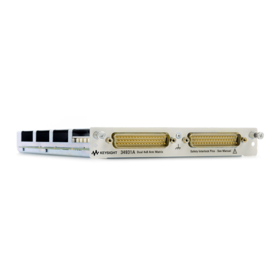
Page 17: 34931A Dual 4X8 Armature Matrix
34931A Dual 4x8 Armature Matrix The 34931A dual 4x8 armature matrix contains two matrices, each with 32 2-wire crosspoint latching armature relays organized in a 4-row by 8-column configuration. Every row and column are made up of two wires each, a high (H) and a low (L). -
Page 18: 34931A Simplified Schematic
ABus1 Row 5 (MEAS) ABus2 Row 6 (SENS) ABus3 Row 7 Row 8 ABus4 NOTE: Matrix 1 and Matrix 2 are electrically separate from one another. NOTE: Matrix Relays: Armature latching Analog Bus Relays: Armature non-latching Keysight 34931A-34933A User’s Guide... -
Page 19: 34931A D-Sub Connectors
R represents “row,” and C represents R2L C8H C8L “column.” 50-Pin D-Sub Male C3L C1H C1L R3H R3L C6H C6L Connector Description Description Description No Connect pins: 3-4, 9-12, 15-22, 25-26, 31-32, 34, and 43-48. Keysight 34931A-34933A User’s Guide... - Page 20 Analog Bus relays, which are on Matrix 2, to close. The optional 34931T terminal block shorts these pins for you. This feature protects inadvertent routing of high voltages from the Analog Buses to the D-sub connector of the module. Keysight 34931A-34933A User’s Guide...
-
Page 21: 34931T Terminal Block
(no terminal block or cable is connected), the Analog Bus relays, which are on Matrix 2, are open and disconnected from the Analog Buses. See page 10 for further information. Keysight 34931A-34933A User’s Guide... - Page 22 On the 34931T terminal block, only two sets of screw terminals are for use with NOTE the 34931A module. See the following drawing. When using the 34931T terminal block, be sure to wire your connections to the two sets of screw terminals closest to the 50-pin D-sub connectors.
-
Page 23: 34932A Dual 4X16 Armature Matrix
When the DMM is scanning, it controls ABus1 and ABus2 relays, which are on NOTE Matrix 2. Therefore, consider this behavior when you are connecting matrices. When the power is off, matrix relays maintain state, and Analog Bus relays open. Keysight 34931A-34933A User’s Guide... -
Page 24: 34932A Simplified Schematic
ABus1 Row 5 (MEAS) ABus2 Row 6 (SENS) Row 7 ABus3 Row 8 ABus4 NOTE: Matrix 1 and Matrix 2 are electrically separate from one another. NOTE: Matrix Relays: Armature latching Analog Bus Relays: Armature non-latching Keysight 34931A-34933A User’s Guide... -
Page 25: 34932A D-Sub Connectors
C1L R3H R3L C6H C6L C10H C10L Male Connector Description Description Description Description Description C12H C12L No Connect pins: 11-12, 17-18, 31-32, C13H 34, and 45-46 C13L C14H C14L C10H C15H C10L C15L C11H C16H C11L C16L Keysight 34931A-34933A User’s Guide... - Page 26 Analog Bus relays, which are on Matrix 2, to close. The optional 34932T terminal block shorts these pins for you. This feature protects inadvertent routing of high voltages from the Analog Buses to the D-sub connector of the module. Keysight 34931A-34933A User’s Guide...
-
Page 27: 34932T Terminal Block
Therefore, you can wire the same-matrix rows in two locations. Although columns are numbered the same on Matrix 1 and Matrix 2, they are electrically separate from one another (e.g., Col C13). Keysight 34931A-34933A User’s Guide... -
Page 28: 34933A Dual/Quad 4X8 Reed Matrix
For example, with one Analog Bus relay closed, you can close up to a maximum of 19 channel relays. If you try to close more than the allowed number of channels, you will receive an error message. Keysight 34931A-34933A User’s Guide... - Page 29 You can connect multiple matrix modules externally and/or through the Analog Buses for applications that require large matrices. For information on linking multiple matrix modules, refer to page 15 of this manual. When the power is off, matrix relays and Analog Bus relays open. Keysight 34931A-34933A User’s Guide...
-
Page 30: 34933A Simplified Schematic For Two-Wire Mode
Matrix 2 Col 1H Col 1L Col 2H Col 2L Col 8H Col 8L bypass bypass bypass bypass bypass bypass Analog Buses ABus1 Row 5 (MEAS) ABus2 Row 6 (SENS) Row 7 ABus3 Row 8 ABus4 Keysight 34931A-34933A User’s Guide... -
Page 31: 34933A D-Sub Connectors For Two-Wire Mode
C6H bypass 25 31-32, 34, and 45-46 C2L bypass 44 C6L bypass 26 C3H bypass 19 C7H bypass 15 C3L bypass 20 C7L bypass 16 C4H bypass 3 C8H bypass 47 C4L bypass 4 C8L bypass 48 Keysight 34931A-34933A User’s Guide... - Page 32 Analog Bus relays, which are on Matrix 2, to close. The optional 34933T-001 (for 2-wire) terminal block shorts these pins for you. This feature protects inadvertent routing of high voltages from the Analog Bus to the D-sub connector of the module. Keysight 34931A-34933A User’s Guide...
-
Page 33: 34933T-001 Terminal Block For Two-Wire Mode
34933T-001 terminal block that corresponds to the 2-wire configuration mode. Note that an error will not be generated if you have installed a terminal block that doesn't match the present module configuration. Keysight 34931A-34933A User’s Guide... - Page 34 C10H C2H bypass C14H C6H bypass C10L C2L bypass C14L C6L bypass C11H C3H bypass C15H C7H bypass C11L C3L bypass C15L CC7L bypass C12H C4H bypass C16H C8H bypass C12L C4L bypass C16L C8L bypass Keysight 34931A-34933A User’s Guide...
-
Page 35: 34933A Simplified Schematic For One-Wire Mode
Row 1 (MEAS) Row 3 Row 4 Row 2 ABus2 Matrix 4 Row 2 (SENS) bypass bypass bypass Row 3 ABus3 Row 3 Row 1 Row 2 Row 4 Row 3 ABus4 Row 4 Row 4 Keysight 34931A-34933A User’s Guide... - Page 36 NOTE – 2R4 means Matrix 2, Row 4. – 1C5 means Matrix 1, Column 5 – 4C2 bypass means: Matrix 4, Column 2, and the connection bypasses the 100Ω in-rush resistor that protects the reed relays Keysight 34931A-34933A User’s Guide...
- Page 37 Analog Bus relays, which are on Matrix 2, to close. The optional 34933T-002 (for 1-wire) terminal block shorts these pins for you. This safety feature protects inadvertent routing of high voltages from the Analog Buses to the D-sub connector of the module. Keysight 34931A-34933A User’s Guide...
- Page 38 34933T-002 terminal block that corresponds to the 1-wire configuration mode. Note that an error will not be generated if you have installed a terminal block that doesn't match the present module configuration. NOTE: Analog Bus connections are on Matrix 3 and Matrix 4. Keysight 34931A-34933A User’s Guide...
- Page 39 34933A channel numbering connector pinouts description linking multiple modules programming examples simplified schematic terminal block wiring log connector pinouts 34931A 34932A 34933A D-sub pinouts 34931A 34932A 34933A Keysight 34931A-34933A User’s Guide...
- Page 40 THIS PAGE HAS BEEN INTENTIONALLY LEFT BLANK. Keysight 34931A-34933A User’s Guide...
- Page 41 This information is subject to change without notice. Always refer to the Keysight website for the latest revision. © Keysight Technologies 2008-2019 Edition 3, July 1, 2019 Printed in Malaysia *34980-90031* 34980-90031 www.keysight.com...
Need help?
Do you have a question about the 34931A and is the answer not in the manual?
Questions and answers