Table of Contents
Advertisement
Quick Links
Advertisement
Table of Contents

Related Manuals for Linde H40D


Summary of Contents for Linde H40D
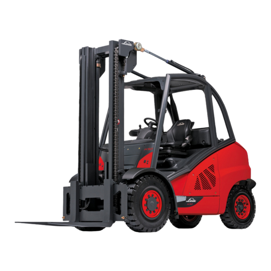
- Page 1 Diesel truck Original instructions H40D, H45D, H50D 394 807 10 01 EN – 07/2011...
- Page 3 Preface Linde − Your Partner With over 100,000 fork lift trucks and ware- Your local Linde partner can offer you a house machines sold annually, Linde is one of complete package from a single source; the world’s leading manufacturers of material ranging from expert advice on all aspects handling equipment.
-
Page 5: Table Of Contents
Table of contents Introduction Your forklift truck ........... . . 2 Proper use . - Page 6 Linde Forklift Data Management (LFM) ........
- Page 7 Table of contents Driving without the lift mast ..........100 Loading .
- Page 8 Table of contents Check suction and exhaust pipes for leaks ....... . . 145 Regenerating the particle filter .
- Page 9 Table of contents Hydraulic system: Check the oil level........175 Hydraulic system: changing the filter .
- Page 10 Table of contents Technical data Type sheet H 40, as at 07/2011 ......... . 208 Type sheet H 45, as at 07/2011 .
- Page 11 Table of contents Special equipment sheet 07 – Truck data management, LPG volume display ..282 Special equipment sheet 08 – LPG volume display for volumetric filling with shut-off valve, changing particle filter, camera system ......284 Special equipment sheet 09 —...
-
Page 13: Introduction
Introduction... -
Page 14: Your Forklift Truck
NOTE inspection and maintenance overview. Please make sure you record the work performed in In the event of repairs, only use genuine Linde the registration document for the industrial spare parts. This is the only way to guarantee truck; this is essential for any warranty claims. -
Page 15: Proper Use
Introduction Description of use and climatic conditions form, equipment and expertise in the interest These operating instructions must not be of progress. reproduced, translated or made accessible to third parties—including as excerpts—except For this reason, no claims can be asserted with the express written approval of the on the basis of the following data, figures and manufacturer. -
Page 16: Symbols Used
Introduction Technical description Symbols used The terms DANGER, WARNING, CAUTION, NOTE NOTE and ENVIRONMENT NOTE are used in these operating instructions for notes on Means that particular attention is drawn to particular hazards or for unusual information combinations of technical factors which may that needs to be highlighted: not be evident even to a specialist. - Page 17 • Ideal visibility due to slim lift mast profiles Linde Load Control • Full load capacity up to maximum lift heights The truck’s Linde Load Control (LLC) control • Enormous residual load capacity electronics system enables: Operating Instructions – 394 807 10 01 EN – 07/2011...
-
Page 18: Truck Operation When Using A Shovel
Introduction Receiving the industrial truck Electrical system • Maintenance-free storage of the lift mast and tilt cylinder via rubber-cushioned The electrical system is powered by the linkage points three-phase alternator with 12 V DC voltage. A • Electric tilt angle limitation. 12 V battery with 88 Ah is installed for starting the engine. -
Page 19: Legal Requirements For Marketing
Introduction Legal requirements for marketing Legal requirements for marketing Declaration Linde Material Handling GmbH Carl-von-Linde-Platz D-63743 Aschaffenburg, Germany We declare that the machine according to these operating instructions Industrial truck Model according to these operating instructions complies with the most recent version of machinery directive 2006/42/EC. - Page 20 Introduction Legal requirements for marketing Operating Instructions – 394 807 10 01 EN – 07/2011...
-
Page 21: Safety
Safety... -
Page 22: Safety Guidelines
Safety Safety guidelines Safety guidelines It is essential that operating personnel and DANGER repair personnel observe the" rules for the In operating areas with magnetic fields that have a proper use of industrial trucks" enclosed with magnetic flux density greater than 5 mT, unintentio- these operating instructions. -
Page 23: Residual Risks
Safety Residual risks WARNING CAUTION In trucks with an accumulator, serious injuries can Various pieces of special equipment are connected occur if the accumulator is not properly handled. to the special "speed reduction" function. This is simply an assistance function, on which the driver Before starting work on the accumulator it must be must not solely rely during operation. -
Page 24: Stability
Safety Handling consumables • Risk caused by insufficient maintenance or testing, • Risk caused by using the wrong consum- ables. Stability Stability is guaranteed if your industrial truck is • turning and driving diagonally across used according to its intended purpose. descents or ascents, •... -
Page 25: Competent Person
Safety Regulations carefully clean the area around the part WARNING involved. The improper handling of coolant and coolant addi- • Dispose of used spare parts in an environ- tives presents a risk to health and the environment. mentally friendly manner. Observe the manufacturer’s instructions without fail. -
Page 26: Instructions For Fitting Attachments
Safety Instructions for fitting attachments There is a recommendation setting out the scope of the periodic safety inspection —FEM 4.004 of the European Industrial Truck Asso- ciation— which defines a test log to document the current safety inspection and an inspection sticker for the next safety inspection. -
Page 27: Fork Carriage Emergency Lowering
Safety Fork carriage emergency lowering Fork carriage emergency lowering If there is a malfunction, the fork carriage can be lowered manually. Remove floormat. DANGER Risk of accident or danger to life when lowering the fork carriage with fork arms. People are not allowed to stand in the vicinity of the fork arms when they are being lowered. -
Page 28: Emergency Exit With Attached Rear Window
Safety Emergency exit with attached rear window Screw the threaded stud (1) back in clock- wise. Otherwise it will not be possible to lift the fork carriage using the joystick. Tightening torque 10 Nm. Retighten the self locking nut (2). Tightening torque 9.5 Nm NOTE After emergency lowering has been perfor-... -
Page 29: Overview
Overview... -
Page 30: Identification Plates
Overview Identification plates Identification plates Nameplate Lift mast number (adhesive label) Serial number (stamped into the front right of the junction plate on the overhead guard) Drive axle identification plate Engine identification plate Operating Instructions – 394 807 10 01 EN – 07/2011... - Page 31 Overview Identification plates Nameplate Nameplate Manufacturer Type/chassis number/year of manufacture Tare weight Placeholder for "data-matrix code" CE mark Rated driving power Rated load capacity NOTE The CE mark confirms compliance with the EC machinery directive and with all regulations applicable to the truck. Steering axle identification plate Steering axle identification plate Operating Instructions –...
-
Page 32: General View
Overview General view General view Lift mast Access cover Lift cylinder Chassis and overhead guard Composite instrument Bonnet Tilt cylinders Step for mounting and dismounting Switch panel for toggle switch (special Fuses (in the engine compartment) equipment) Left drive unit Joystick Fork carriage Steering wheel/hydrostatic power steering... -
Page 33: Operating Devices
Overview Operating devices Operating devices Indicator light for turn indicator and hazard Symbol label for auxiliary hydraulics (attach- warning system (green) (special equipment) ments) (special equipment) Clamping screw for adjusting the steering Symbol label for working hydraulics column Signal button Multifunction lever for wiper/washer system Armrest on driver’s seat and turn indicator (special equipment) -
Page 34: Display Unit
Overview Display unit Display unit Operating Instructions – 394 807 10 01 EN – 07/2011... - Page 35 Overview Display unit Display unit Symbol without function Hydraulic oil temperature indicator Function key Charging indicator Reset button Engine oil pressure indicator / engine oil Time display level indicator (special equipment) "Do not start the engine" symbol Electrical controller fault Symbol for "Parking brake applied"...
- Page 36 Overview Display unit Possible malfunctions Display element Function Remedy V-ribbed belt split or v-ribbed belt tension too slack V-ribbed belt tensioner faulty Cable faulty (3) Charging indicator - Lights up if there are Alternator faulty (red) generator malfunctions. Charging controller or cut-out relay faulty Short circuit at output D+ of the display unit...
- Page 37 Overview Display unit Possible malfunctions Display element Function Remedy - Lights up when the particle Regenerate the particle filter filter control system is immediately activated, if the load period of the particle filter exceeds 8.5 h (8) Particle filter error - Additionally, a buzzer sounds (red) and an error code appears in...
- Page 38 Overview Display unit Possible malfunctions Display element Function Remedy If a faulty display unit is Indicates the operating hours replaced, the operating hours of the truck. This display up to that point must be is evidence of the truck’s recorded. Affix the data on an (17) Operating hours display operating time and of the embossed strip near the display...
- Page 39 Overview Display unit Possible malfunctions Display element Function Remedy Charge status display: Serves as display field for error - 0 symbols blacked out => code display and charge status Text field (28) particle filter empty display for the particle filter (in - 11 symbols blacked out =>...
-
Page 40: Switch Panel
Overview Switch panel Switch panel The switch panel is mounted at the top right of the val depends on the drive direction and the overhead guard. washer system is always activated) Interior lighting Roof panel wiper - intermittent mode or Standard or higher lighting continuous operation on/off (washer system Working spotlight position 1/2... -
Page 41: Operation
Operation... -
Page 42: Service Plan Before Initial Commissioning
Operation Running-in instructions Service plan before initial commissioning Carried Engine Fill up with fuel Check the engine oil level Checking the coolant level Regenerate the particle filter Chassis frame Tighten wheel fastenings Check the tyre pressure Checking the brake system Check steering system. -
Page 43: Pre-Shift-Checks
Operation Pre-shift-checks Pre-shift-checks Carried Engine Check the fuel level Check the engine oil level Checking the coolant level Chassis frame Check the tyre pressure Check the condition of the antistatic belt (only when using tyres that are not antista- tic) Hydraulics Hydraulic system: Check the oil level. -
Page 44: Standard Equipment
Operation Standard equipment Standard equipment Entering and exiting the truck WARNING Entering and exiting the truck can result in injuries to the feet or back. Always face the truck when you enter or exit the truck. NOTE Do not use the steering wheel or the actuating levers as an aid to get in or out. - Page 45 Operation Standard equipment NOTE Sitting for long periods of time puts a lot of pressure on the spine. Try to compensate for this by performing regular simple gymnastic movements. Longitudinal adjustment Pull lever (1) upwards. Move the driver’s seat backwards or for- wards on the runners to find the most com- fortable position for the driver in relation to the steering wheel and the accelerator ped-...
-
Page 46: Adjusting The Height-Adjustable Comfort Driver's Seat
Operation Standard equipment Adjusting the lumbar support (only with a comfort driver’s seat) NOTE The lumbar support enables optimum configu- ration of the seat back contour to the driver’s body. Turn knob (5) to the left or right. The extent to which the lower and upper areas of the backrest are curved is adjusted individually. - Page 47 Operation Standard equipment Longitudinal adjustment Pull lever (1) upwards. Move the driver’s seat backwards or for- wards on the runners to find the most com- fortable position for the driver in relation to the steering wheel and the accelerator ped- als.
-
Page 48: Adjusting The Luxury Driver's Seat
Operation Standard equipment Adjusting the lumbar support NOTE The lumbar support enables optimum configu- ration of the seat back contour to the driver’s body. Turn knob (5) to the left or right. The extent to which the lower and upper areas of the backrest are curved is adjusted individually. - Page 49 Operation Standard equipment NOTE Sitting for long periods of time puts a lot of pressure on the spine. Try to compensate for this by performing regular simple gymnastic movements. Longitudinal adjustment Pull lever (1) upwards. Move the driver’s seat backwards or for- wards on the runners to find the most com- fortable position for the driver in relation to the steering wheel and the accelerator ped-...
- Page 50 Operation Standard equipment Adjusting the seat angle Pull lever (3) upwards. The seat surface is moved to the desired position by applying pressure to the seat surface or removing pressure from it. Adjusting the seat depth Pull lever (4) upwards. The seat surface can be moved to the desired position by sliding the seat surface forwards or backwards.
-
Page 51: Adjusting The Armrest
Operation Standard equipment Adjusting the luxury active driver’s seat The luxury active driver’s seat is operated in exactly the same way as the luxury driver’s seat. Only the activation of the seat heater is different. Activating the seat heater (luxury active driver’s seat) Push the switch (9) upwards to activate the seat heater. -
Page 52: Adjusting The Steering Column
Operation Standard equipment Adjusting the steering column DANGER Safe driving is not guaranteed with the clamping screw open. Only adjust the steering column when the vehicle is stationary. Angle adjustment Undo the clamping screw (2) anticlockwise. Move the steering wheel (1) into the re- quired position. -
Page 53: Seat Belt
Operation Standard equipment Press both push buttons (2) and (3) simulta- neously for 3 seconds. The hour readout in the time display (1)blinks. NOTE The hours or minutes can be adjusted gradu- ally by pressing push button (2) or quickly by holding down the push button. - Page 54 Operation Standard equipment "speed reduction" special function, the seat belt must be worn even at the reduced speed. The automatic blocking mechanism prevents the belt from being extended whenever the industrial truck is on a steep slope. It is then not possible to pull the belt any further out of the retractor.
-
Page 55: Drive Engine (Dual-Pedal Operation)
Operation Standard equipment Drive engine (dual-pedal operation) Starting the engine DANGER Risk of poisoning! Do not allow the engine to run in unventilated areas. NOTE Where possible, avoid frequently starting and stopping the engine over short periods of time, since this prevents the internal combustion engine from reaching its operating tempera- ture. - Page 56 Operation Standard equipment Look at the display unit (4). NOTE After the ignition has been switched on, the display unit will perform a self-test. The displays all light up for approx. 2 seconds and the operating hours until the next service are displayed for 5 seconds in the display unit (4) display field (10).
- Page 57 Operation Standard equipment temperature and altitude, this may take more than 1 minute. If the engine stalls, the "Do not start the engine" symbol will appear (11). NOTE A block against repeat starting is active and the engine cannot be started. Always leave the ignition switched on until the symbol goes out.
-
Page 58: Driving (Dual-Pedal Operation)
Operation Standard equipment Take your feet off the accelerator pedals (3). Turn the switch key (2) to the zero position. NOTE The brake is applied when the engine is switched off. Turn the parking brake lever (1) in a clock- wise direction until it engages. - Page 59 Operation Standard equipment NOTE The forklift truck can only be driven with the driver’s seat under load. Start the engine. Slightly raise fork arms and tilt lift mast back. Release the parking brake (unlock the park- ing brake lever (1) and move it downwards as far as the stop).
- Page 60 Operation Standard equipment Approaching gradients Press the stop pedal (3) all the way down. Release the parking brake lever (1) and move it downwards as far as the stop. Take your foot half way off the stop pedal. Actuate accelerator pedal (2) or (4). Slowly take your foot completely off the stop pedal.
-
Page 61: Drive Engine (Single-Pedal Operation)
Operation Standard equipment Drive engine (single-pedal opera- tion) Starting the engine DANGER Risk of poisoning! Do not allow the engine to run in unventilated areas. NOTE Where possible, avoid frequently starting and stopping the engine over short periods of time, since this prevents the internal combustion engine from reaching its operating tempera- ture. - Page 62 Operation Standard equipment Place your foot on accelerator pedal (3). Turn the parking brake lever (1) in a clock- wise direction until it engages. The parking brake is actuated (it is only possible to start the engine with the parking brake actuated).
- Page 63 Operation Standard equipment Wait until the glow plug indicator (14) goes Turn switch key to position "II". As soon as the engine starts: Release the switch key. Symbol (8) flashes. CAUTION Only in trucks with a particle filter system. If the exhaust continues to be very smoky, switch off the truck.
- Page 64 Operation Standard equipment brisk speed. The engine will quickly reach its operating temperature. Switching off the engine CAUTION For engines with a turbocharger, the high speed of the turbocharger shaft (approx. 100,000 rpmat full load) could cause the shaft bearing to run dry through lack of lubrication, thus damaging it.
-
Page 65: Driving (Single-Pedal Operation)
Operation Standard equipment Driving (single-pedal operation) WARNING It is generally not permitted to drive on long gra- dients over 15% due to specified minimum braking and stability values. Please contact your authori- sed dealer before driving on larger gradients. The climbing capability values given in the type sheet have been determined from the pulling force and only apply when overcoming obstacles on the road-... - Page 66 Operation Standard equipment Release the parking brake (unlock the park- ing brake lever (1) and move it downwards as far as the stop). Forwards travel Move the direction of travel lever (4) for- wards. Press the accelerator pedal (3) carefully. The driving speed of the truck increases as the actuation distance of the pedal increases.
- Page 67 Operation Standard equipment Approaching gradients Press the stop pedal (2) all the way down. Release the parking brake lever (1) and move it downwards as far as the stop. Take your foot half way off the stop pedal. Press accelerator pedal (3). Slowly take your foot completely off the stop pedal.
-
Page 68: Steering System
Operation Standard equipment Steering system Steering The hydrostatic steering system means that very little effort is required for the steering wheel turning movement. This is particularly advantageous when palletising in narrow aisles. Starting and driving. Turn the steering wheel to the left and right as far as it will go. - Page 69 Operation Standard equipment certain circumstances, can cause the load to slip from the fork arms. In unfavourable situations, the engine can also stall; as a result the "Do not start the engine" symbol (3) appears in the display unit. A block against repeat starting is active and the engine cannot be started.
-
Page 70: Signal Horn
Operation Standard equipment Press the button (1). The parking brake is unlocked. Move the parking brake (2) down as far as the stop. The symbol on the indicator unit will go out. DANGER The forklift truck must not be driven if the braking system is defective. -
Page 71: Joystick With Central Lever Operation
Operation Standard equipment Joystick with central lever operation WARNING There is a risk of becoming trapped between parts due to the moving lift mast or the attachment. Therefore, never reach into or enter the lift mast or the area between the lift mast and the truck. - Page 72 Operation Standard equipment Lifting the fork carriage DANGER There is an increased risk of falling and crushing when lifting the lift mast. For this reason, it is not permitted to step onto the raised fork arms. Push joystick (1) to the right. Lowering the fork carriage Push joystick (1) to the left.
- Page 73 Operation Standard equipment CAUTION Attachments affect the load capacity and stability of the truck. Attachments that are not supplied with the truck should only be used if the authorised dealer has checked that the arrangement in terms of load capacity and stability ensures safe operation. NOTE The methods of attachment operation descri- bed here are examples.
- Page 74 Operation Standard equipment Operating the fork prong positioner NOTE In order to prevent damage, do not activate the fork prong positioner with a load, or with the fork arms on the ground. Do not use the fork prong positioner as a clamp. Push the joystick (2) forwards.
- Page 75 Operation Standard equipment Push joystick (2) forwards by at least 40% and then move to the zero position. Joystick is unlocked for approx. one second and the display (3) lights up in the display unit. NOTE If the joystick is not moved forwards within this time period, it is locked again.
- Page 76 Operation Standard equipment Take note of the switching symbols with arrows. Unlock the joystick (4) (depending on the version) by pressing the knob downwards. Push the joystick (4) forwards. Clamp opens. Pull the joystick (4) backwards. Clamp closes. Once the joystick has been released, it is locked again.
-
Page 77: Joystick With Single Lever Operation
Operation Standard equipment Joystick with single lever operation WARNING There is a risk of becoming trapped between parts due to the moving lift mast or the attachment. Therefore, never reach into or enter the lift mast or the area between the lift mast and the truck. - Page 78 Operation Standard equipment Lifting the fork carriage DANGER There is an increased risk of falling and crushing when lifting the lift mast. For this reason, it is not permitted to step onto the raised fork arms. Pull the joystick (1) backwards. Lowering the fork carriage Push the joystick (1) forwards.
- Page 79 Operation Standard equipment CAUTION Attachments affect the load capacity and stability of the truck. Attachments that are not supplied with the truck should only be used if the authorised dealer has checked that the arrangement in terms of load capacity and stability ensures safe operation. NOTE The methods of attachment operation descri- bed here are examples.
- Page 80 Operation Standard equipment Operating the fork prong positioner NOTE In order to prevent damage, do not activate the fork prong positioner with a load, or with the fork arms on the ground. Do not use the fork prong positioner as a clamp. Push the joystick (4) forwards.
- Page 81 Operation Standard equipment Version 1: Electronically locked Take note of the switching symbols with arrows. Push joystick (4) (depending on the version) forwards by at least 40% and then move to the zero position. Operating Instructions – 394 807 10 01 EN – 07/2011...
- Page 82 Operation Standard equipment Joystick is unlocked for approx. one second and the display (6) lights up in the display unit. NOTE If the joystick is not moved forwards within this time period, it is locked again. Push the joystick (4) forwards. Clamp opens.
-
Page 83: Special Equipment
Operation Special equipment Unlock the joystick (4) (depending on the version) by pressing the knob downwards. Push the joystick (4) forwards. Clamp opens. Pull the joystick (4) backwards. Clamp closes. Once the joystick has been released, it is locked again. Special equipment Depressurisation When replacing hydraulic components or... -
Page 84: Driver's Cab
Operation Special equipment Driver’s cab Opening the cab door Push handle (4) upwards. Open driver’s door outwards. Closing the cab door NOTE To make it easier to close the door, open the side window slightly. Grip the rod (5) and pull the door towards you until the interlock engages. - Page 85 Operation Special equipment Switching on the interior lighting Press toggle switch (1). Switching on the lighting. Move toggle switch (2) to centre position. The sidelights and licence plate light are switched on. Switch toggle switch (2) as far as it will go. The dipped beams, sidelights and licence plate lights are switched on.
-
Page 86: Windscreen Wiper
Operation Special equipment Switching on the direction indicators Move operating lever (7) on steering wheel forwards. The flashing lights flash on the right. Indicator lamp (8) flashes. Move operating lever (7 ) on steering wheel backwards. The flashing lights flash on the left. Indicator lamp (8) flashes. - Page 87 Operation Special equipment Move the actuating lever (1) on the steering wheel upwards from the centre position. The front windscreen wiper remains in inter- mittent mode as long as the lever is actuated. Press the actuating lever (1) on the steering wheel downwards from the centre position.
- Page 88 Operation Special equipment Move the actuating lever (1) on the steering wheel upwards from the centre position. As long as the lever is actuated, the front windscreen wiper remains in intermittent mode and the rear window wiper remains in continuous mode. Press the actuating lever (1) on the steering wheel downwards from the centre position.
-
Page 89: Window Heater
Operation Special equipment mode and the roof panel wiper remains in continuous mode. Press the actuating lever (1) on the steering wheel downwards from the centre position. The front windscreen wiper is in intermittent mode and the roof panel wiper is in continuous mode. -
Page 90: Heating System, Air Conditioning
Operation Special equipment Heating system, air conditioning Heating system operating devices • Turning knob (1) for temperature control • Turning knob (2) for setting the blower positions • Rotary switch (3) for setting the vent posi- tions for windscreen defrosting / footwell ventilation •... - Page 91 Operation Special equipment Air conditioning operating devices • Turning knob (5) for temperature control • Function display (6) • Push-button (7) for switching the air condi- tioning on • Rotary switch (8) for setting the blower positions • Turning knob (9) for setting the vent posi- tions for windscreen defrosting / footwell ventilation •...
- Page 92 Operation Special equipment Close windows and doors, rotate turning knob (5) anti-clockwise and increase the blower speed using switch (8). NOTE To achieve maximum cooling in the cab: the air conditioning must be switched on, • the turning knob (5) must be fully turned to •...
-
Page 93: Linde Forklift Data Management (Lfm)
Operation Special equipment Linde Forklift Data Management (LFM) Truck data acquisition The truck data acquisition (FDE) input device (1) is located in the armrest console (3). The input device has a 12-digit keypad (2). With the standard setting, a 5-digit PIN is... - Page 94 Operation Special equipment NOTE If you only notice one of these statuses (such as a problem with driving) after you have input the status code (truck OK), you have to log off. Rotate the turning knob (6) anticlockwise to the stop. Log in again with status message (prob- lem with driving)
- Page 95 Operation Special equipment Press the (4) button to start the input device. The green LED (2) flashes. Enter personal PIN (factory setting = ) and status code. 0 0 0 Therefore, for a properly set-up truck, the PIN should be as follows: 0 0 0 0 0 NOTE If the PIN was input incorrectly, press the...
- Page 96 Operation Special equipment Switch off the truck and log off: Rotate the turning knob (6) anticlockwise to the stop. The engine is turned off. NOTE After a delay time (factory setting = 10 se- conds) the red LED (1) lights up briefly, and the green (2) and red (1) LEDs then flash for approx.
- Page 97 Operation Special equipment Press the (4) button to start the input device. The green LED (2) flashes. Enter personal PIN (factory setting = 0 0 0 NOTE If the PIN was input incorrectly, press the button (4) and enter the correct PIN. Confirm the entry with the button (3).
- Page 98 Operation Special equipment Switch off the truck and log off: Rotate the turning knob (6) anticlockwise to the stop. The engine is turned off. NOTE After a delay time (factory setting = 10 se- conds) the red LED (1) lights up briefly, and the green (2) and red (1) LEDs then flash for approx.
- Page 99 Operation Special equipment Logging on and starting the truck: Apply the parking brake. Fold open the armrest support on the side to the right. Place the valid transponder on the field (3). Data is read in and the green LED (2) lights up with a steady light.
-
Page 100: Adjusting The Driver's Seat With Rotating Device
Operation Special equipment Switch off the truck and log off: Rotate the turning knob (6) anticlockwise to the stop. The engine is turned off. NOTE After a delay time (factory setting = 10 se- conds) the red LED (1) lights up briefly, and the green (2) and red (1) LEDs then flash for approx. -
Page 101: Lift Mast Positioning
Operation Special equipment Pull locking lever (1) backwards. The rotating device is enabled and allows the seat to be rotated 17° to the right. It can be locked at 0° and at 17°. Allow the locking bolt to audibly snap into place. - Page 102 Operation Special equipment Press the push button (2) at the front left-hand side of the armrest for longer than 2 seconds. The tilt angle is now permanently stored. As confirmation, a double acoustic signal sounds from the display unit and the light in the button (2) flashes briefly several times.
-
Page 103: Working Under Load
Operation Working under load Working under load Before taking up a load Before taking up a load, check the load capacity diagram above the switch console on the top right in the overhead guard. Max. weight of permissible loads in Height of lift in mm Series designation of truck with max. - Page 104 Operation Working under load loads involving a large centre of gravity • distance Before transporting loads in a wind force of • 6 and upwards Example Load centre of gravity distance: 650 mm Load height to be lifted: 6800 mm Trace a vertical line from a load distance of 650 mm to its point of intersection with the line for a lift height of 6800 mm.
-
Page 105: Adjusting The Fork Spread
Operation Working under load In addition, affix the label (5) next to the basic load capacity diagram. Adjusting the fork spread NOTE The load centre should be in the centre between the forks. Raise the fork quick-release levers(1). Move the forks further apart or closer together depending to the size of the load to be lifted. -
Page 106: Taking Up Load
Operation Working under load Taking up load DANGER Danger of a falling load. Standing or walking in the vicinity of an elevated mast is extremely dangerous. During stacking and de-stacking operations do not allow people to stand or walk in the working area of the truck. -
Page 107: Travelling With Load
Operation Working under load Set lift mast to vertical. Lift or lower the fork carriage to the neces- sary height. Carefully steer the truck forks beneath the centre of the load to be taken up, where possible so the load touches the fork back, taking account of adjacent loads. -
Page 108: Setting Down Loads
Operation Working under load Setting down loads DANGER Never stop and leave the vehicle with the load still raised. Let down the fork carriage until the fork arms touch the ground. Carefully move the forklift truck to the load / storage area. -
Page 109: Before Leaving The Lift Truck Unattended
Operation Before leaving the lift truck unattended Turn the handle (1) of the towing pin 90° towards the rear and lift it up. Place the drawbar eye into the coupling sleeve (2). Push the towing pin down against the spring pressure, turn 90°... -
Page 110: Loading / Transporting
Operation Loading / Transporting Rotate the parking brake lever (1) in a clockwise direction until it engages. The parking brake is now applied. Switch off the engine. Remove the ignition key (2). Loading / Transporting Securing the hose pulley against rolling up When fitting single auxiliary hydraulics, a hose pulley (1) is located beneath the floorplate... -
Page 111: Removing The Lift Mast
Operation Loading / Transporting Turn the hexagon head screw (3) on the hose pulley (1) in the direction of travel (right) with a wrench (SW 10) to the stop in the secure position (6). The safety catch (2) points against the direc- tion of travel and the slotted spring pin (8) is visible;... -
Page 112: Driving Without The Lift Mast
Operation Loading / Transporting Driving without the lift mast CAUTION When driving without the lift mast, the speed of the truck must be reduced for safety reasons. Therefore, before removing the lift mast, an addi- tional stop screw must be fitted under the reverse travel accelerator pedal (dual-pedal operation) or accelerator pedal (single-pedal operation) to re- strict the speed. - Page 113 Operation Loading / Transporting WARNING Crane loading may cause damage to the tilt cylin- ders and the cover sheet on the counterweight. Retract the lift mast, retract the tilt cylinders as far as the stop and lift the truck in such a way that it hangs at an angle towards the front.
-
Page 114: Transportation By Lorry Or Low Loading Trucks
Operation Loading / Transporting Attach chains (6) (min. load capac- ity: 4000 kg) to the lifting eyes (7) on the counterweight. Attach chains (2) (min. load capac- ity: 4000 kg) to the lifting eyes (1) on the lift mast. Make sure that the safety lock (5) is closed. NOTE During lifting, the lifting gear should not touch the overhead guard, the cover sheet on the... -
Page 115: Maintenance
Maintenance... -
Page 116: General Information
Maintenance General information General information Your forklift truck will only remain in a state WARNING ready for use at all times if you perform a small Any side doors fitted could fall shut during mainten- number of maintenance and inspection tasks ance work and trap staff. -
Page 117: Inspection And Maintenance Data
See sticker on inside of Tyres Pneumatic overhead guard Wheel fastenings Tighten front: 425 Nm rear: 640 Nm Load chains / Lift mast Linde chain spray As required channels Air conditioning Refrigerant 1600 grams Recommendations for consumables Diesel fuel malfunctions. For this reason, cold-resistant "winter"... - Page 118 Chain spray your authorised dealer. Manufacturer’s ap- Linde chain spray (order no.: see spare parts proval has been granted only for the oils listed catalogue). above. Mixing or using with other hydraulic fluids may result in highly expensive damage.
- Page 119 Maintenance Recommendations for consumables off ("consumed"), but the temperature stress NOTE and the fuel combustion products that enter the oil lead to "wear", affecting especially the API or ACEA oils are only permitted if they fulfil chemical "additives" in the oil. For this reason, the VW standards (referred to above) for the the entire filling of engine oil must be renewed pump injection engine.
-
Page 120: Inspection And Maintenance Overview
Maintenance Inspection and maintenance overview Inspection and maintenance overview Service plan as required Carried Engine Clean the fuel tank ventilation hose Drain water from the fuel filter Change the air filter cartridge (after no longer than 1000 operating hours) Change the safety cartridge in the air filter (after no longer than 3000 operating hours) Check the dust discharge valve Change the oil bath air filter oil... -
Page 121: 1000 H Service Plan
Maintenance Inspection and maintenance overview 1000 h service plan At operating hours 1000 2000 4000 5000 7000 Carried 8000 10000 11000 13000 14000 16000 17000 19000 20000 Information on service plan Dependent on the consumables used, the driving style and the operating conditions, but at least every 12 months. - Page 122 Maintenance Inspection and maintenance overview At operating hours 1000 2000 4000 5000 7000 Carried 8000 10000 11000 13000 14000 16000 17000 19000 20000 Chassis, tilt cylinders and steering axle: check the mountings Check and grease other bearings and joints Chassis frame Check the parking brake for correct operation Clean and grease steering axle Steering cylinder and steering pivot pin: check the mountings...
-
Page 123: 3000 H Service Plan
Maintenance Inspection and maintenance overview 3000 h service plan Carried At operating hours 3000 15000 Information on service plan Dependent on the consumables used, the driving style and the operating conditions, but at least every two years. Refer also to the recommendation for consumables. Preparations Clean the truck (if necessary) Read out error memory and delete... - Page 124 Maintenance Inspection and maintenance overview Carried At operating hours 3000 15000 Hydraulic pump on engine: check the mountings Chassis, bodywork and fittings Chassis, tilt cylinders and steering axle: check the mountings Check and grease other bearings and joints Chassis frame Check the parking brake for correct operation Clean and grease steering axle Steering cylinder and steering pivot pin: check the mountings...
- Page 125 Maintenance Inspection and maintenance overview Carried At operating hours 3000 15000 Carry out functional test and test drive Attach maintenance sticker Operating Instructions – 394 807 10 01 EN – 07/2011...
-
Page 126: 6000 H Service Plan
Maintenance Inspection and maintenance overview 6000 h service plan Carried At operating hours 6000 12000 Information on service plan Dependent on the consumables used, the driving style and the operating conditions, but at least every three years. Refer also to the recommendation for consumables. Preparations Clean the truck if necessary Read out error memory and delete... - Page 127 Maintenance Inspection and maintenance overview Carried At operating hours 6000 12000 Hydraulic pump on engine: check the mountings Chassis, bodywork and fittings Chassis, tilt cylinders and steering axle: check the mountings Check and grease other bearings and joints Chassis frame Check the parking brake for correct operation Clean and grease steering axle Steering cylinder and steering pivot pin: check the mountings...
- Page 128 Maintenance Inspection and maintenance overview Carried At operating hours 6000 12000 Carry out functional test and test drive Attach maintenance sticker Operating Instructions – 394 807 10 01 EN – 07/2011...
-
Page 129: 9000 H Service Plan
Maintenance Inspection and maintenance overview 9000 h Service plan Carried At operating hours 9000 18000 Information on service plan Dependent on the consumables used, the driving style and the operating conditions, but at least every four years. Refer also to the recommendation for consumables. Preparations Clean the truck (if necessary) Read out error memory and delete... - Page 130 Maintenance Inspection and maintenance overview Carried At operating hours 9000 18000 Drive axle: check the side stops Drive axle: check the bearing for wear Hydraulic pump on engine: check the mountings Chassis, bodywork and fittings Chassis, tilt cylinders and steering axle: check the mountings Check and grease other bearings and joints Chassis frame Check the parking brake for correct operation...
- Page 131 Maintenance Inspection and maintenance overview Carried At operating hours 9000 18000 Check slide guides on sideshift for wear Subsequent tasks Carry out functional test and test drive Attach maintenance sticker Operating Instructions – 394 807 10 01 EN – 07/2011...
-
Page 132: Engine
Maintenance Engine Engine Checking the engine oil level ENVIRONMENT NOTE Observe information regarding working with consumables WARNING When topping up the oil, no oil should drip on to hot engine parts — Risk of fire! Fill carefully. CAUTION Different oil specifications. Observe the recommendations for consumables. -
Page 133: Change Engine Oil
Maintenance Engine Change engine oil (at the latest after 12 months) CAUTION Different oil grades result in different maintenance intervals. Recommendations for consumables must always be observed. Draining the engine oil WARNING Risk of scalding when draining hot engine oil! Protective equipment must be worn. - Page 134 Maintenance Engine Remove the filler cap (1) from the filling opening. Remove cover on floor of frame. Unscrew the engine oil drain plug (3) underneath from the oil sump. Allow all oil to drain off into collection vessel. Fit the drain plug (3) with a new sealing ring. Tightening torque: 30 Nm Refit the cover (1).
-
Page 135: Changing The Engine Oil Filter
Maintenance Engine Open the filler cap (1) of the filling opening. Pour new engine oil into the filling opening according to the recommendations for consumables. Fill quantity with filter change: max. 4.5 l Using the dipstick (2), check the engine oil level after adding oil and top up to max. -
Page 136: Fuel
Maintenance Engine Release the cap (1) from the engine oil filter (2) with a 32 AF open-ended spanner and unscrew by hand. Collect oil that escapes from the oil filter and dispose of it and the oil filter in an environmentally friendly manner. - Page 137 Maintenance Engine The fuel tank level display on the display unit (4) shows the current fuel level. The tank is full when all 7 LEDs (2) and the petrol pump illuminated field (1) light up green. As the fuel tank empties, the LEDs are extin- guished, starting from the right.
-
Page 138: Draining Water From The Fuel Filter
Maintenance Engine Draining water from the fuel filter. ENVIRONMENT NOTE Observe information regarding working with consumables. Unscrew 3 screws from the maintenance cover on the right side of the forklift truck. Remove the maintenance cover. Open the drainage screw (1) on the fuel filter and drain approx. -
Page 139: Clean The Fuel Tank Ventilation Hose
Maintenance Engine Unscrew 3 screws from the maintenance cover (1) on the right side of the forklift truck. Remove the maintenance cover. Place a collection vessel under the fuel filter (2). Clean the outside of the fuel filter. Unscrew the old filter and dispose of it in an environmentally friendly manner. -
Page 140: Checking The Coolant Level
Maintenance Engine Disconnect the hose (1) from the pipe union at the fuel signal transmitter and blow dry compressed air through it. Slide the hose (1) onto the pipe union as far as the stop. d3941342 Checking the coolant level ENVIRONMENT NOTE Observe information regarding working with consumables. -
Page 141: Changing The Coolant
Maintenance Engine Open the bonnet. The coolant level should not be below the mark at the inspection window (2). If necessary, top up the coolant. To do this, twist and remove the filler cap (3) at the counterweight. WARNING The expansion reservoir is under pressure! Risk of scalding due to hot coolant. - Page 142 Maintenance Engine WARNING Never open the filler cap (2) when the engine is hot. Risk of scalding! Wait until the coolant has cooled down. ENVIRONMENT NOTE Observe information regarding working with consumables. Open the bonnet. Place a collection container under the coolant hose (6).
-
Page 143: Checking The Coolant Concentration
Maintenance Engine Read off the filling level in filler neck. • Min. marking is the edge (4) of the lower step. • Max. marking is the edge (5) of the upper step. Difference in quantity between min. and max.: approx. 0.75 l Filling quantity in cooling system without heating system and air conditioning: 8.5 l... - Page 144 Maintenance Engine WARNING Never open the filler cap (2) when the engine is hot. Risk of scalding! Wait until the coolant has cooled down. ENVIRONMENT NOTE Observe information regarding working with consumables. Check the coolant concentration at the filling opening (1). The frost protection should be sufficient for temperatures down to -25°C.
-
Page 145: Cleaning The Water Cooler And Hydraulic Oil Cooler, And Checking Them For Leaks
Maintenance Engine Close the bonnet. Cleaning the water cooler and hydraulic oil cooler, and checking them for leaks NOTE Only clean the water cooler and hydraulic oil cooler when the engine is switched off and has cooled down. Open the bonnet. Release the 5 screws (2). -
Page 146: Checking The Condition And Secure Positioning Of The Engine Support And Engine Mounting
Maintenance Engine Cleaning with compressed air Blow out the cooler (3) from the engine side using compressed air. Rinse out the released dirt using a water jet. Cleaning with cleaner solvent CAUTION Humidity must not penetrate the three-phase alternator. Therefore, protect it from direct contact with the water jet. -
Page 147: Check Condition Of The Ribbed Vee Belt
Maintenance Engine Check rubber elements for cracks and se- vere deformation; if necessary, exchange them. Please contact your authorised dealer. Check all screws and nuts in the engine support and engine mounts for damage. Check that they are securely attached. Tightening torques of the mounting screws and nuts: Engine, right:... -
Page 148: Replacing Ribbed V-Belt
Maintenance Engine Open the bonnet. Remove the maintenance cover on the right hand side. Check the ribbed V-belt (1) for signs of excessive wear, frayed edges, cracks across the belt and traces of oil. Exchange the ribbed vee belt if it is dam- aged. -
Page 149: Checking The Condition And Tension Of Toothed Belt
Maintenance Engine Mark the running direction of the ribbed V-belt (3). Swing away (2) the tensioner pulley, (1) using a flat 16 AF ring spanner at the tensioning lever. @@@@ @@@@ @@@@ @@@@ @@@@ @@@@ @@@@ @@@@ @@@@ @@@@ @@@@ @@@@ @@@@ @@@@... - Page 150 Maintenance Engine Check that the pointer (5) is positioned centrally in front of the gap in the baseplate. To readjust or change the toothed belt, please contact your authorised dealer Check the water pump gear (2) for wear. Place a knife edge (1) on the tooth (4) and use a feeler gauge to establish the thinning (3) over the length of the tooth.
-
Page 151: Renew The Toothed Belt And Idler Pulley
Maintenance Engine Renew the toothed belt and idler pulley NOTE Special know-how and tools are required for the renewal of the toothed belt and idler pulley. Please contact your authorised dealer for this service. d3921410 Change the water pump NOTE Changing the water pump requires specialist knowledge and special tools. - Page 152 Maintenance Engine Open the bonnet. Open the 3 fasteners (2) and remove the air filter cover (3). Pull out the air filter cartridge. CAUTION Clean the inside of the air filter housing thoroughly. Do not blow it out with compressed air. Wipe the housing clean with a clean cloth.
-
Page 153: Changing The Air Filter Safety Cartridge
Maintenance Engine Changing the air filter safety car- tridge Change the safety cartridge (1): • Two years after it has entered operation at the latest. • If the air filter vacuum display lights up again immediately after the air filter cartridge has been serviced. -
Page 154: Changing The Breather Filter For The Charge Air Pressure Regulator
Maintenance Engine Compress the valve (1) and remove the remaining dust. If the value is damaged, replace it. Close the bonnet. Changing the breather filter for the charge air pressure regulator ENVIRONMENT NOTE Observe information regarding working with consumables. Open the bonnet. Both filters are located at the back right-hand side next to the engine. -
Page 155: Cleaning The Prefilter (Special Equipment)
Maintenance Engine Cleaning the prefilter (special equipment) NOTE The dust collecting tank must never be more than half full with dust. If there is a heavy accumulation of dust, the tank must be emptied every day. Open the dust collecting tank (1) by turning to the right (clockwise). -
Page 156: Change The Oil In The Oil Bath Air Cleaner (Optional)
Maintenance Engine Open fasteners (4) on oil tank (3). Remove oil tank (downwards), then empty and clean. Clean and check seals (2) and change if damaged. Loosen the air hose clip on the clean air connection (1) and remove the hose. Detach and clean dust collecting tank (8). -
Page 157: Check Suction And Exhaust Pipes For Leaks
Maintenance Engine Open the clamps (3) on the oil bowl (2). Remove the oil bowl downwards, empty and clean it. Clean and check ((1)) the seals, renew if damaged. Check the filter element ((5)) and clean if dirty. Fill the oil bowl (2) with engine oil up to the mark(4). -
Page 158: Regenerating The Particle Filter
Maintenance Engine Remove the cover on the counterweight. Check the connections of the exhaust pipe in the counterweight, and ensure that it is securely fastened and there are no leaks. Re-tighten the fixing screws if necessary. Refit the covering on the counterweight. d3941366 Regenerating the particle filter The particle filter must be regenerated after... - Page 159 Maintenance Engine If this time period is exceeded, the load indicator (4) continues to flash and the particle filter alarm (3) lights up on the display unit (1). In addition, a buzzer sounds continuously and the engine speed is reduced so that the truck moves only at creep speed.
- Page 160 Maintenance Engine ation can be started at any time within this period. Press the starting switch (7) in the switch panel downwards and hold for approx. 3 seconds until the integrated yellow switch illumination (operating display) lights up. The particle filter alarm (3) goes out in the display unit.
-
Page 161: Regenerating The Changing Particle Filter
Maintenance Engine Regenerating the changing particle filter The particle filter must be regenerated after a maximum of 8.5 h engine operation. After 8.0 hours, the orange indicator light (1) illuminates in the switch panel at the top-right as an optical display, and a buzzer sounds. The clogged up filter must be changed for a regenerated filter within the next 30 minutes. - Page 162 Maintenance Engine Remove the retaining split pin (3) from the quick-locking mechanisms. Release quick-locking mechanisms (2) and (9) and disconnect the rod (6) at the top at the filter. Remove the retaining split pin (7) at the contact protection. Fold out the contact protection (4). Use the bracket (5) to do this.
-
Page 163: Checking The Particle Filter System (Special Equipment)
Maintenance Engine Press the STOP switch (15) in the event of danger. Only press the STOP switch in an emergency! The filter must then be fully regenerated again. An indicator light (13) will illuminate if there is a malfunction during regeneration. Press the acknowledgement button (14). -
Page 164: Draining Water From The Water Trap At The Changing Particle Filter (Special Equipment)
Maintenance Engine To do so, release the olive screw joint and remove particulate deposits using a round steel brush. Check that the screws on the filter housing and the exhaust-gas-conducting parts are securely fitted. Check the glow plug coil for serious defor- mation and coking. -
Page 165: Cleaning The Pressure Control Device At The Changing Particle Filter (Special Equipment)
Maintenance Engine Unscrew the sight glass (1) and wipe out with a clean cloth. If necessary, completely dismantle the water trap and blow out with compressed air. Cleaning the pressure control device at the changing particle filter (special equipment) NOTE Only for particle filters with a changing particle filter system. -
Page 166: Gearbox
Maintenance Gearbox Gearbox Axle clamps and wheel motors: checking the mountings Check that the 4 mountings screws (M20) (1) of the axle clamps have a tightening torque of 540 Nm. Check that the mountings screws (M16) (ar- rows) of the wheel motors have a tightening torque of 275 Nm. -
Page 167: Checking The Drive Axle Bearings For Wear
Maintenance Gearbox Checking the drive axle bearings for wear NOTE The drive axle is installed in the chassis with rubber spring elements on both sides. Remove the drive wheels. Using a lamp, check the state of the rubber spring elements (1) between the axle, chassis and plastic stops. -
Page 168: Chassis, Bodywork And Fittings
Maintenance Chassis, bodywork and fittings Chassis, bodywork and fittings Cleaning the truck Cleaning requirements depend on the use of CAUTION the truck. For operations with highly abrasive When cleaning with a water jet (high-pressure materials, e.g. salt water, fertiliser, chemicals, or steam cleaner etc.), it should not be applied cement etc., thorough cleaning should be directly to the electric and electronic components,... - Page 169 Maintenance Chassis, bodywork and fittings Pull the lever (1) upwards and push the driver’s seat forwards as far as it will go. Release the lever (1) and allow the seat to engage. If a rear window is installed, push the lever (3) upwards and hold, fold the seat backrest (4) all the way forwards and release the lever (3) .
-
Page 170: Floorplate
Maintenance Chassis, bodywork and fittings Undo the clamping screw (9) in the armrest (8) and push the armrest fully downwards. Retighten clamping screw (9). If a rear window is installed, the armrest fore/aft adjustment must also be pushed all the way forwards. -
Page 171: Maintaining The Heating System And Air Conditioning (Special Equipment)
Maintenance Chassis, bodywork and fittings Remove the rubber covering from the floorplate (1). Unscrew the fixing screws (2) from the floorplate. Swing the floorplate up. Place restraint strap (3) around the knob on the steering wheel. Closing the floorplate Lift up the floorplate. Detach the restraint strap. -
Page 172: Checking The Condition And Correct Function Of The Seat Belt
Maintenance Chassis, bodywork and fittings Remove the cover (1). Remove the filter (2) and clean or replace. Reinsert the filter and fit the cover. Unscrew the screws (4). Remove the air duct (3). Remove the filter (5) and clean or replace. Reinsert the filter and attach the air duct with screws. - Page 173 Maintenance Chassis, bodywork and fittings NOTE For safety reasons, check the restraint system regularly (once a month) for function and good condition. Screw connections should be checked regu- larly to make sure that they are secure. The seat belt must be replaced after an accident.
-
Page 174: Check Fastening For Frame, Tilt Cylinders And Steering Axle
Maintenance Chassis, bodywork and fittings Open the bonnet with driver’s seat (4) by approx. 30°. The automatic mechanism should block extension of the belt from the belt retractor (2). Check fastening for frame, tilt cylinders and steering axle Check 6 fastening bolts (M 30) (1) of frame have a tightening torque of 1350 Nm. -
Page 175: Topping Up The Washer System Water Tank (Special Equipment)
Maintenance Chassis, bodywork and fittings • Seat guide • Bonnet pivot pin • Wiper mounting (option) • Cab door hinges and locks (option) • Grease the bonnet latch. Topping up the washer system water tank (special equipment) Open the bonnet. Remove the filler cap (1) from the water tank (2) at the right-hand side of the engine compartment. -
Page 176: Chassis Frame
Maintenance Chassis frame Chassis frame Changing a wheel WARNING Note the tare weight of the truck. Only use jacks with a load capacity of at least 3600 kg. CAUTION When using wheels that are not antistatic, pay attention to the antistatic belt. When changing wheels that are not antistatic, the truck must be equipped with an antistatic belt as these wheels are not electroconductive. -
Page 177: Tighten The Wheel Nuts
Maintenance Chassis frame Tighten the wheel nuts The wheel fasteners must be tightened before the commissioning and after each wheel change and repair. Then after 100 service hours minimum. Tighten opposite wheel fasteners to a torque front 425 Nm rear 640 Nm Check the tyres for damage and foreign objects... -
Page 178: Checking The Tyre Pressure
Maintenance Chassis frame Checking the tyre pressure CAUTION If the air pressure is too low, the tyres’ service life will be reduced and the stability of the truck will be compromised. Therefore, regularly check tyre pressures. Check that the tyres are at the correct pressure. -
Page 179: Checking The Condition Of The Antistatic Belt
Maintenance Chassis frame Checking the condition of the antistatic belt driven into an area with a sealed floor, the NOTE electrostatic charging effect occurs very often. Under certain circumstances the truck may become electrostatically charged. Non-scrubbing tyres are identified by the •... -
Page 180: Checking The Mountings Of The Steering Cylinder And Steering Pivot Pin
Maintenance Chassis frame Clean steering axle with water or cleaner solvent. NOTE Lubricating grease should be used for grea- sing in accordance with consumables recom- mendations. First grease the axle stub bear- ings on top, then underneath. Grease the tie rod and axle stubs at the lubricating nipples (see arrows) using lubricating grease. -
Page 181: Controls
Maintenance Controls Controls Checking the parking brake for correct operation Drive the fork lift truck, carrying its maximum load, up a gradient of 15 %. Place the parking brake (2) in a horizontal position. The vehicle must remain stationary. Switch off the engine. Press the button (1) and unlock the parking brake lever (2). -
Page 182: Checking The Bellows At The Actuating Lever
Maintenance Controls Checking the bellows at the actuat- ing lever Check that the bellows (1), (2) and (3) (depending on the version) are securely positioned and show no signs of damage. Change if necessary. Operating Instructions – 394 807 10 01 EN – 07/2011... -
Page 183: Electrics
Maintenance Electrics Electrics Check the condition and secure positioning of electric cables, cable connectors and connections NOTE Oxidised connections and brittle cables lead to voltage drops and thus to difficulties during start-up and operation. Check cable terminals for secure attach- ment and oxidation residues. - Page 184 Maintenance Electrics Before recharging, first check battery without electric load to make sure that only intact batteries undergo charging. During electrical charging, batteries pro- duce hydrogen and oxygen gas which under certain conditions may result in an explosive mixture. Battery should only be filled and charged in well ventilated rooms.
- Page 185 Maintenance Electrics Inspect battery (1) for cracked housing, raised plates and acid leaks. Unscrew sealing plugs (2) and check acid level. In the case of batteries with level checking inserts, the fluid must reach the bottom of the insert, and for batteries without level checking inserts, it must lie 10–15 mm above the lead plates.
-
Page 186: Hydraulics
Maintenance Hydraulics Hydraulics Change hydraulic oil Drain hydraulic oil ENVIRONMENT NOTE Observe information regarding working with consumables. Drive truck over pit. Fully lower fork carriage and lift mast. Place a collection vessel under the left side of the truck floor. Open the bonnet. -
Page 187: Hydraulic System: Check The Oil Level
Maintenance Hydraulics Refill/top up hydraulic oil Add hydraulic oil to filling port. Total fill quantity: approx. 27.8 l Check oil level with dipstick (3) and top up further until upper marking (4) is reached on dipstick. Allow engine to idle for 3 minutes in upper range (parking brake applied and accelera- tor pedal depressed). -
Page 188: Hydraulic System: Changing The Filter
Maintenance Hydraulics Unscrew the breather filter (1) with oil dipstick on the left side of the vehicle. NOTE Tank under low pressure. A small amount of air will escape. Wipe the oil dipstick with a clean cloth. Screw the breather with dipstick (2) in completely and then unscrew it again. - Page 189 Maintenance Hydraulics Lower the lift mast Slacken the lower mounting screw (2) and the upper mounting screw (1) on the filter carrier. Swing out the filter carrier. Place a collection vessel underneath. Slacken the pressure filter housing (3) and the feed filter housing (4) at the hexagonal section.
- Page 190 Maintenance Hydraulics Open the breather filter (5). This allows the air to escape so that the oil will not overflow when the filter cartridge is inserted. Turn the filter cover (6) in an anti-clockwise direction and unscrew it. Slowly remove the filter cartridge. This will allow the oil to flow back into the container.
-
Page 191: Check The Bleeder Valve On The Hydraulic Oil Tank For Correct Operation
Maintenance Hydraulics Unscrew the filter (5) for the hydraulic oil tank from the filler neck. Remove the dipstick (7) from the breather filter and attach it to the new filter. Screw in the filter and tighten it. Close the bonnet. Check the bleeder valve on the hy- draulic oil tank for correct operation NOTE... -
Page 192: Check The Hydraulic System For Leaks
Maintenance Hydraulics Check the hydraulic system for leaks Open the bonnet. Raise and secure the floor plate. Check all connections between the oil tank, drive motors, pumps and control valves for leaks. Tighten connections if necessary. Check the lift, tilt and steering cylinders for leaks. -
Page 193: Check The Tension Of Double Hoses
Maintenance Hydraulics Check the tension of double hoses The tension of the double hoses should be 5-10 mm per metre, depending upon the original length. Adjust the tension of the hoses to the specified dimension by sliding them in the clamps. -
Page 194: Load Lift System
Maintenance Load lift system Load lift system Working on the lift mast and at the front of the truck DANGER When working on the lift mast, there is a risk of becoming trapped and/or the lift mast accidentally lowering. If the lift mast or fork carriage is raised, no work must be performed on the lift mast or at the front of the forklift truck without observing the following safety measures! These safety precautions are... - Page 195 Maintenance Load lift system Connect the chain over the cross beam of the outer mast (1) and under the cross beam of the inner mast (2). Lower the inner mast until it reaches the chain. Duplex lift mast NOTE The advantage of this version is that full advantage is taken of the special free lift height even in very low rooms (cellars, wagons, ships).
- Page 196 Maintenance Load lift system Connect the chain over the cross beam of the outer mast (1) and under the cross beam of the inner mast (2). Lower the lift mast until the end of the chain. Lower fork carriage as far as it will go. Triplex lift mast FUNCTION: The fork carriage is lifted to the special free lift height via the chain guide pulley...
-
Page 197: Cleaning And Spraying The Lift Mast Chain
The chain should be moved several times during this process. Immediately apply Linde chain spray to chain, moving chain while doing so. Operating Instructions – 394 807 10 01 EN – 07/2011... -
Page 198: Lift Mast, Lift Mast Chains, Lift Cylinder And End Stops: Check Mounting, Condition And Function
Maintenance Load lift system Lift mast, lift mast chains, lift cylinder and end stops: Check mounting, condition and function Clean lift mast guides and chain. Check chain for condition and wear, espe- cially at guide pulleys. Check that the chain is attached securely to the chain anchor. - Page 199 In the case of trucks that are used in the food production sector, chain spray should not be used. Instead, use a low-viscosity oil licensed for use in the food industry. Apply Linde chain spray to guide surfaces and chain. Duplex lift mast or triplex lift mast NOTE The lift mast chain stretches over time during operation and therefore has to be readjusted.
-
Page 200: Check The Forks And Fork Quick-Releases
In the case of trucks that are used in the food production sector, chain spray should not be used. Instead, use a low-viscosity oil licensed for use in the food industry. Apply Linde chain spray to guide surfaces and chain. Check the forks and fork quick- releases Check the forks for visible deformations, wear and damages. -
Page 201: Clean Sideshift (Special Equipment) And Grease, Check Fastening
Maintenance Load lift system Clean sideshift (special equipment) and grease, check fastening ENVIRONMENT NOTE Observe information about working materials. NOTE The sideshift should be greased whenever the truck is washed. Use lubricating grease complying with the recommendations for working materials. Clean sideshift with steam jet. -
Page 202: Checking The Slide Guides On The Sideshift (Special Equipment) For Wear
Maintenance Load lift system Checking the slide guides on the sideshift (special equipment) for wear Dismantle sideshift. Clean sideshift. Remove the slide guides from the upper guide (1). Measure the wall thickness of the slide guide (3). If wall thickness is less than 2.5 mm, change the slide guides. -
Page 203: Self-Help
Maintenance Self-help Self-help Opening the cover to the electrical system Depending on the set-up, up to 40 fuses may be installed in the electrical system in order to protect it. The fuse box can be accessed after removing the cover of the electrical system. Unscrew both handles(2). -
Page 204: Fuses For Basic And Special Equipment
Maintenance Self-help Fuses for basic and special equipment Checking and changing fuses 12 V socket (9F10)*, 15 A Blower toothed belt sealing (0F1)*, 10 A or Heating/air conditioning (9F9)*, 20 A Time-delayed lighting off (F17)*, 2 A Seat heater (9F6)*, 20 A Particle filter (7F3)*, 30 A Warning light and rotating beacon (4F3)*, Particle filter (7F2)*, 20 A... -
Page 205: Diagnostic Connector
Maintenance Self-help Open the covering of the fuse box. In the engine compartment, MTA fuses protect the following circuits: • Fuse (F1) (1) for glow and fuel system, 50 A • Main fuse (F2) (2) for complete electrical system, 40 A •... -
Page 206: Malfunctions During Operation
Maintenance Self-help Malfunctions during operation CAUTION If one of the following indicator lights illuminates in the display unit and the buzzer sounds during operation, a malfunction has occurred. The engine must be shut down immediately and the malfunction dealt with. (See: Malfunctions, Causes and Remedy) •... - Page 207 Maintenance Self-help appears in the text field (10) of the display unit, a fault occurred during regeneration. Restart regeneration procedure. Only if a changing particle filter is fitted: • If the orange indicator light (14) lights up in the switch panel in the top right and a buzzer sounds, the filter must be changed or regenerated within the next 30 minutes.
-
Page 208: Malfunctions, Causes And Remedies (Diesel Engine)
Maintenance Self-help Malfunctions, Causes and Remedies (diesel engine) Engine will not start Remedy Possible cause Fuel tank empty. Fill up the tank. Fuel filter clogged, caused in winter by paraffin Change the filter. Use winter fuel. segregation. Water in the fuel filter. Drain water from the fuel filter. - Page 209 Maintenance Self-help Particle filter system warning lamp flashes and buzzer sounds when ignition is switched on. Possible cause Remedy Check the lamp: switch on the glow plug starting switch using the switch key. Both Switch illumination in the start switch and switch illuminations briefly light up once, if emergency stop switch for the particle filter not, change the indicator light.
- Page 210 Maintenance Self-help Engine oil pressure too low. Switch off engine immediately. Possible cause Remedy Leakages in the lubricating system. Contact your authorised dealer. Top up with engine oil Oil level too low Charging current indicator lamp lights up during operation. Remedy Possible cause Three-phase alternator speed too low.
-
Page 211: Malfunctions, Causes And Remedies (Hydraulic System)
Maintenance Self-help Malfunctions, causes and remedies (hydraulic system) Abnormal noise. Remedy Possible cause Clogged suction filter. Change the filter. Seal the lines. Check the hydraulic oil, top up if Leaking suction lines, oil foams. necessary. Hydraulic pump or engine damage, faulty Have the hydraulic unit checked by your seals, causing air intake. - Page 212 Maintenance Self-help No or too little supply flow. Possible cause Remedy Valves clogged. Contact your authorised dealer. Check hydraulic oil level, use prescribed Hydraulic system overheated. hydraulic oil, if any, clean the hydraulic oil cooler. Hydraulic oil temperature too high. Remedy Possible cause Pump damaged, valves leaking.
-
Page 213: Jump Start
Maintenance Self-help Jump start NOTE When the truck battery is discharged, a jump-start battery can be used with a jumper cable to start the truck. The following must be taken into consideration when doing this: Both batteries must have the same nominal •... -
Page 214: Towing
Maintenance Self-help If the engine does not start straightaway, abort the starting process after 10 seconds and try again after around 30 seconds. Once the engine is running, first disconnect the negative cable (4) from the engine block (3), and then from the current-giving battery (5). - Page 215 Maintenance Self-help Use a socket to release the self-locking nut (1) (AF 19 mm) on the left-hand side of the variable displacement pump housing. Unscrew threaded stud (2) (AF 8 mm) 2 turns using the socket. Lock the threaded stud with the self-locking nut (1), and tighten to 50 Nm.
- Page 216 Maintenance Self-help Replace floor mat and close bonnet. DANGER The forklift truck must not be driven if the braking system is defective. After repairs to the brake system, check for correct operation. If there are any defects in the brake system, contact your authorised dealer.
-
Page 217: Shutting Down
Maintenance Shutting down Shutting down Shutting down the truck Measures before shutdown This will prevent permanent deformation of the tyres. If the truck is to be shut down for more than two months, e.g. for operational reasons, NOTE it must only be stored in a well ventilated, clean and dry room that is frost-protected. -
Page 218: Disposal Of Old Trucks
Maintenance Shutting down Disposal of old trucks The disposal of old trucks is regulated in available for disassembled and partially directive 2000/53/EC from the European oil-smeared parts, as well as for tyres Parliament and Council. including fire protection measures. Suitable storage tanks for fluids such as fuel, engine We therefore recommend having this work oil, hydraulic oil, coolant and fluids from... -
Page 219: Technical Data
Technical data... -
Page 220: Type Sheet H 40, As At 07/2011
Type sheet H 40, as at 07/2011 Type sheet H 40, as at 07/2011 All data refers to standard equipment with a standard 3000 mm lift mast. Please note the following: 1 Characteristics Manufacturer Linde Manufacturer’s type designation H 40 D Drive Diesel Operation... - Page 221 Technical data Type sheet H 40, as at 07/2011 4 Basic dimensions [mm] 3000 Lift Raised mast height [mm] 3795 Overhead guard height (cab) [mm] 2383 Seat height, min./max. [mm] 1226 4.12 Coupling height [mm] 4.19 Total length [mm] 3984 4.20 Length including fork back [mm] 2984...
- Page 222 Technical data Type sheet H 40, as at 07/2011 7 Drive/engine Nominal speed 2800 Number of cylinders/displacement 4/1968 Fuel consumption in accordance with VDI cycle 8 Miscellaneous Hydrostatic / Traction controller type continuously variable Working pressure for attachments Oil volume for attachments l/min dB (A) Noise level in forklift driver’s ear...
-
Page 223: Type Sheet H 45, As At 07/2011
Type sheet H 45, as at 07/2011 Type sheet H 45, as at 07/2011 All data refers to standard equipment with a standard 3000 mm lift mast. Please note the following: 1 Characteristics Manufacturer Linde Manufacturer’s type designation H 45 D Drive Diesel Operation... - Page 224 Technical data Type sheet H 45, as at 07/2011 4 Basic dimensions [mm] 3000 Lift Raised mast height [mm] 3916 Overhead guard height (cab) [mm] 2416 Seat height, min./max. [mm] 1264 4.12 Coupling height [mm] 4.19 Total length [mm] 4066 4.20 Length including fork back [mm] 3066...
- Page 225 Technical data Type sheet H 45, as at 07/2011 7 Drive/engine Nominal speed 2800 Number of cylinders/displacement 4/1968 Fuel consumption in accordance with VDI cycle 8 Miscellaneous hydrostatic / Traction controller type continuously variable Working pressure for attachments Oil volume for attachments l/min dB (A) Noise level in forklift driver’s ear...
-
Page 226: Type Sheet H 50/500, As At 07/2011
Type sheet H 50/500, as at 07/2011 Type sheet H 50/500, as at 07/2011 All data refers to standard equipment with a standard 3000 mm lift mast. Please note the following: 1 Characteristics Manufacturer Linde Manufacturer’s type designation H 50 D Drive Diesel Operation... - Page 227 Technical data Type sheet H 50/500, as at 07/2011 4 Basic dimensions [mm] 3000 Lift Raised mast height [mm] 3916 Overhead guard height (cab) [mm] 2416 Seat height, min./max. [mm] 1264 4.12 Coupling height [mm] 4.19 Total length [mm] 4116 4.20 Length including fork back [mm] 3116...
- Page 228 Technical data Type sheet H 50/500, as at 07/2011 7 Drive/engine Nominal speed 2800 Number of cylinders/displacement 4/1968 Fuel consumption in accordance with VDI cycle 8 Miscellaneous Hydrostatic / Traction controller type continuously variable Working pressure for attachments Oil volume for attachments l/min dB (A) Noise level in forklift driver’s ear...
-
Page 229: Type Sheet H 50/600, As At 07/2011
Type sheet H 50/600, as at 07/2011 Type sheet H 50/600, as at 07/2011 All data refers to standard equipment with a standard 2800 mm lift mast. Please note the following: 1 Characteristics Manufacturer Linde Manufacturer’s type designation H 50 D/600 Drive Diesel Operation... - Page 230 Technical data Type sheet H 50/600, as at 07/2011 4 Basic dimensions [mm] 2800 Lift Raised mast height [mm] 3816 Overhead guard height (cab) [mm] 2416 Seat height, min./max. [mm] 1264 4.12 Coupling height [mm] 4.19 Total length [mm] 4396 4.20 Length including fork back [mm] 3196...
- Page 231 Technical data Type sheet H 50/600, as at 07/2011 7 Drive/engine Nominal speed 2800 Number of cylinders/displacement 4/1968 Fuel consumption in accordance with VDI cycle 8 Miscellaneous hydrostatic Traction controller type /continuously variable Working pressure for attachments Oil volume for attachments l/min dB (A) Noise level in forklift driver’s ear...
-
Page 232: Type Sheet H 40 Elevated Driver's Compartment, As At 07/2011
Type sheet H 40 elevated driver’s compartment, as at 07/2011 Type sheet H 40 elevated driver’s compartment, as at 07/2011 All data refers to standard equipment with standard 3900 mm lift mast. Please observe the following: 1 Identification Manufacturer Linde Manufacturer’s type designation H 40 D Drive Diesel Operation... - Page 233 Technical data Type sheet H 40 elevated driver’s compartment, as at 07/2011 4 Basic dimensions [mm] 3900 Lift Raised mast height [mm] 4695 Overhead guard height (cab) [mm] 2783 Seat height, min./max. [mm] 1626 4.12 Coupling height [mm] 4.19 Total length [mm] 3984 4.20 Length including fork back...
- Page 234 Technical data Type sheet H 40 elevated driver’s compartment, as at 07/2011 7 Drive/engine Nominal speed 2800 Number of cylinders/displacement 4/1968 Fuel consumption in accordance with VDI cycle 8 Miscellaneous hydrostatic/con- Traction controller type tinuously variable Working pressure for attachments Oil volume for attachments l/min dB (A)
-
Page 235: Type Sheet H 45 Elevated Driver's Compartment, As At 07/2011
Type sheet H 45 elevated driver’s compartment, as at 07/2011 Type sheet H 45 elevated driver’s compartment, as at 07/2011 All data refers to standard equipment with standard 3800 mm lift mast. Please observe the following: 1 Identification Manufacturer Linde Manufacturer’s type designation H 45 D Drive Diesel Operation... - Page 236 Technical data Type sheet H 45 elevated driver’s compartment, as at 07/2011 4 Basic dimensions [mm] 3800 Lift Raised mast height [mm] 4716 Overhead guard height (cab) [mm] 2816 Seat height, min./max. [mm] 1664 4.12 Coupling height [mm] 4.19 Total length [mm] 4066 4.20 Length including fork back...
- Page 237 Technical data Type sheet H 45 elevated driver’s compartment, as at 07/2011 7 Drive/engine Nominal speed 2800 Number of cylinders/displacement 4/1968 Fuel consumption in accordance with VDI cycle 8 Miscellaneous hydrostatic/con- Traction controller type tinuously variable Working pressure for attachments Oil volume for attachments l/min dB (A)
-
Page 238: Type Sheet H 50/500 Elevated Driver's Compartment, As At 07/2011
Type sheet H 50/500 elevated driver’s compartment, as at 07/2011 All data refers to standard equipment with standard 3800 mm lift mast. Please observe the following: 1 Identification Manufacturer Linde Manufacturer’s type designation H 50 D Drive Diesel Operation Seated... - Page 239 Technical data Type sheet H 50/500 elevated driver’s compartment, as at 07/2011 4 Basic dimensions [mm] Free lift Lift [mm] 3800 Raised mast height [mm] 4716 Overhead guard height (cab) [mm] 2816 Seat height, min./max. [mm] 1664 4.12 Coupling height [mm] 4.19 Total length [mm]...
- Page 240 Technical data Type sheet H 50/500 elevated driver’s compartment, as at 07/2011 7 Drive/engine Nominal speed 2800 Number of cylinders/displacement 4/1968 Fuel consumption in accordance with VDI cycle 8 Miscellaneous hydrostatic/con- Traction controller type tinuously variable Working pressure for attachments Oil volume for attachments l/min dB (A)
-
Page 241: Type Sheet H 40 Container, As At 07/2011
Type sheet H 40 container, as at 07/2011 Type sheet H 40 container, as at 07/2011 All data refers to standard equipment with triplex 4075 mm lift mast. Please observe the following: 1 Identification Manufacturer Linde Manufacturer’s type designation H 40 D Drive Diesel Operation... - Page 242 Technical data Type sheet H 40 container, as at 07/2011 4 Basic dimensions Overhead guard height (cab) [mm] 2220 Seat height, min./max. [mm] 1151 4.12 Coupling height [mm] 4.19 Total length [mm] 3984 4.20 Length including fork back [mm] 2984 [mm] 4.21 Total width 1487/1423...
- Page 243 Technical data Type sheet H 40 container, as at 07/2011 8 Miscellaneous hydrostatic Traction controller type /continuously variable Working pressure for attachments Oil volume for attachments l/min dB (A) Noise level in driver’s ear Towing hook, type/model DIN 15170-H Operating Instructions – 394 807 10 01 EN – 07/2011...
-
Page 244: Type Sheet H 45 Container, As At 07/2011
Type sheet H 45 container, as at 07/2011 Type sheet H 45 container, as at 07/2011 All data refers to standard equipment with triplex 4045 mm lift mast. Please observe the following: 1 Identification Manufacturer Linde Manufacturer’s type designation H 45 D Drive Diesel Operation... - Page 245 Technical data Type sheet H 45 container, as at 07/2011 4 Basic dimensions Overhead guard height (cab) [mm] 2220 Seat height, min./max. [mm] 1151 4.12 Coupling height [mm] 4.19 Total length [mm] 4024 4.20 Length including fork back [mm] 3024 [mm] 4.21 Overall width 1487/1423...
- Page 246 Technical data Type sheet H 45 container, as at 07/2011 8 Miscellaneous hydrostatic Traction controller type /continuously variable Working pressure for equipment Oil volume for attachments l/min dB (A) Noise level in driver’s ear Towing hook, type/model DIN 15170-H Operating Instructions – 394 807 10 01 EN – 07/2011...
-
Page 247: Type Sheet H 50/500 Container, As At 07/2011
Type sheet H 50/500 container, as at 07/2011 Type sheet H 50/500 container, as at 07/2011 All data refers to standard equipment with triplex 4045 mm lift mast. Please observe the following: 1 Identification Manufacturer Linde Manufacturer’s type designation H 50 D Drive Diesel Operation... - Page 248 Technical data Type sheet H 50/500 container, as at 07/2011 4 Basic dimensions Overhead guard height (cab) [mm] 2220 Seat height, min./max. [mm] 1151 4.12 Coupling height [mm] 4.19 Total length [mm] 4074 4.20 Length including fork back [mm] 3074 [mm] 4.21 Overall width 1487/1423...
- Page 249 Technical data Type sheet H 50/500 container, as at 07/2011 8 Miscellaneous hydrostatic Traction controller type /continuously variable Working pressure for equipment Oil volume for attachments l/min dB (A) Noise level in driver’s ear Towing hook, type/model DIN 15170-H Operating Instructions – 394 807 10 01 EN – 07/2011...
-
Page 250: Type Sheet H 50/600 Container, As At 07/2011
Type sheet H 50/600 container, as at 07/2011 Type sheet H 50/600 container, as at 07/2011 All data refers to standard equipment with triplex 3745 mm lift mast. Please note the following: 1 Characteristics Manufacturer Linde Manufacturer’s type designation H 50 D/600 Drive Diesel Operation... - Page 251 Technical data Type sheet H 50/600 container, as at 07/2011 4 Basic dimensions Overhead guard height (cab) [mm] 2220 Seat height, min./max. [mm] 1151 4.12 Coupling height [mm] 4.19 Total length [mm] 4354 4.20 Length including fork back [mm] 3154 [mm] 4.21 Total width 1487/1423...
- Page 252 Technical data Type sheet H 50/600 container, as at 07/2011 8 Miscellaneous hydrostatic Traction controller type /continuously variable Working pressure for attachments Oil volume for attachments l/min dB (A) Noise level in forklift driver’s ear Towing hook, type/model DIN 15170-H Operating Instructions –...
-
Page 253: Truck Configuration
Technical data Truck configuration Truck configuration "Truck configuration" sign NOTE If attachments and conversions are required, please contact your authorised dealer. A new "truck configuration" sign must then be created and attached to the truck by the authorised dealer. Frame number Lift mast number or identification: "CO"* Capacity rating plate number... -
Page 254: Tyre Variants And Rim Sizes
Technical data Tyre variants and rim sizes Tyre variants and rim sizes Tyre variants Single tyre on the drive axle SE solid rubber tyres Pneumatic tyres 250-15/18 PR 10.0 bar H 40 250–15 250 R15-XZM 10.0 bar 250/70 R15/18 PR 10.0 bar H 40/45/50-500 28x12.5–15... - Page 255 Technical data Tyre variants and rim sizes Rim sizes Tyre size Rim size 8.25–15 (SE) 6.50–15 250-15 and 8.25-15 (air) 7.00–15 8.00–15 300-15 and 315-15 9.75–15 28x12.5-15 and 355/65-15 28x10x22 Operating Instructions – 394 807 10 01 EN – 07/2011...
-
Page 256: Load Capacity Diagrams And Lift Mast Data As At 07/2011
Technical data Load capacity diagrams and lift mast data as at 07/2011 Load capacity diagrams and lift mast data as at 07/2011 Main dimensions Operating Instructions – 394 807 10 01 EN – 07/2011... - Page 257 Technical data Load capacity diagrams and lift mast data as at 07/2011 Load capacity diagrams The load capacity diagrams apply to Standard and Duplex lift masts with solid rubber tyres and a fork carriage. Lift mast data The lift mast data applies to standard equipment with solid rubber tyres and a fork carriage. Standard lift mast (in mm) Overall heights H 40...
- Page 258 Technical data Load capacity diagrams and lift mast data as at 07/2011 Duplex lift mast (in mm) Overall heights when H 40 2325 2375 2425 2675 2875 retracted with specified free H 45/50 2376 2426 2476 2726 2926 lift H 50/600 Free lift H 40 1561...
-
Page 259: Additional Capacity Rating Plate For Attachments
Linde. Additional capacity rating plate for attachments with loads that are not clamped Truck series (year of manufacture, from - to) -
Page 260: Noise Emission Values
Technical data Noise emission values Additional capacity rating plate for attachments with loads that are fixed or clamped Truck series (year of manufacture, from - to) behaviour: at a load centre of gravity Lift mast type (series) 650 mm = 4,560 kg. Lift heights Specifies in mm how much the load centre Attachments... -
Page 261: Vibration Characteristic Values For Bodily Vibrations
Technical data Acoustic pressure level in the driver’s Guaranteed sound power level compartment in accordance H 40, H 45, 99 dB (A) with 200/14/EC 79 dB (A) H 50-500 Directive 82 dB (A) in LIFT mode Under the terms of the directive, it is a statutory 70 dB (A) in IDLING mode requirement to provide this information. - Page 262 Technical data Operating Instructions – 394 807 10 01 EN – 07/2011...
- Page 263 Index Accumulator ..... 14 Cab door Additional capacity rating plate for Closing ..... . . 72 attachments .
- Page 264 Index Checking the condition and secure Cleaning positioning of electric cables ..171 Lift mast chain ....185 Checking the condition and secure Oil bath air filter .
- Page 265 Index Driver’s seat (comfort seat with height Emergency lowering ....15 adjustment) Engine Adjusting ..... 34 Starting (dual-pedal operation) .
- Page 266 Index Heating system ....78 Lifting the fork carriage Maintaining ....159 Central lever operation .
- Page 267 Index Operating the fork prong positioner Ribbed vee belt Central lever operation ... 62 check condition ....135 Single lever operation .
- Page 268 ... . . 284 Linde Load Control ....5 Sheet 09 — battery main switch with Linde Truck Control .
- Page 269 Index Transportation by lorry or low loading Type sheet H 50/600 container ..238 trucks ....102 Tyre variants .
- Page 272 Linde Material Handling GmbH 394 807 10 01 EN – 07/2011...
-
Page 273: Annex
Diesel truck Original instructions Annex H40D, H45D, H50D 394 807 10 01 EN – 07/2011... -
Page 275: Circuit Diagrams
Circuit diagrams... -
Page 276: Wiring Diagram
Circuit diagrams Wiring diagram Wiring diagram Basic equipment for diesel with pump injection engine — Sheet 01 Operating Instructions – 394 807 10 01 EN – 07/2011... - Page 277 Circuit diagrams Wiring diagram Legend 60 W signal horn, 73 3-pin plug connector (S2), 13–14 Grey Tank transmitter, 33 Electronic starter relay, 11–15 18-pin plug connector (central electrical Orange 0B16 Oil level sensor, 36–37 1.7 kW starter motor, 9–11 system), 19, 64–69 40 A fuse, 4 Display unit, 25–40 9-pin plug connector (central electrical...
-
Page 278: Basic Equipment For Diesel With Pump Injection Engine - Sheet 02
Circuit diagrams Wiring diagram Basic equipment for diesel with pump injection engine — sheet 02 Operating Instructions – 394 807 10 01 EN – 07/2011... - Page 279 Circuit diagrams Wiring diagram Legend :A34 — Tilt forwards (A2) :K90 — Terminal 50 Solenoid valve "z" backwards, 105 Speed actual-value transmitter, 82–85 :A35 — Tilt backwards (B2) :K93 — 5 V sensor, lift Exhaust valve, 95 Accelerator dual potentiometer, 87–92 :A36 —...
-
Page 280: Basic Equipment For Diesel With Pump Injection Engine - Sheet 03
Circuit diagrams Wiring diagram Basic equipment for diesel with pump injection engine — sheet 03 Operating Instructions – 394 807 10 01 EN – 07/2011... - Page 281 Circuit diagrams Wiring diagram Legend Control unit for diesel direct injection system, 0Y13 Pump/nozzle valve for 3rd cylinder, 221 White Engine speed transmitter, 225-228 176-228 0Y14 Pump/nozzle valve for 4th cylinder, 223 Yellow Fuel temperature transmitter, 215 Automatic preheating time control unit, 0Y16 Shut-off flap valve, 206 The number in front of the wire colour refers...
-
Page 282: Special Equipment Sheet 01 - Working Spotlight
Circuit diagrams Wiring diagram Special equipment sheet 01 — working spotlight Operating Instructions – 394 807 10 01 EN – 07/2011... - Page 283 Circuit diagrams Wiring diagram Arrangement Right lift mast working spotlight, 55 W Working spotlight switch (positions 1, 2), Wire colours Working spotlight positions 1, 2 (position 6), 27 10–13 Black Working spotlight positions 1, 2 with higher Upper rear right working spotlight 55 W Working spotlight switch (positions 3, 4, 5, Brown lighting...
-
Page 284: Special Equipment Sheet 02 - Windscreen Wipers, Seat Heater, Seat With Air Suspension
Circuit diagrams Wiring diagram Special equipment sheet 02 — Windscreen wipers, seat heater, seat with air suspension Operating Instructions – 394 807 10 01 EN – 07/2011... - Page 285 Circuit diagrams Wiring diagram Arrangement 24 W rear wash pump, 132 Windscreen wiper central on/off switch, Brown Rear window heating 24 W roof wash pump, 135 103–108 Blue Windscreen wipers 9M10 Compressor motor for seat with air suspen- Front/rear windscreen wiper program Green Seat with seat heater sion 90 W...
-
Page 286: Special Equipment Sheet 03 - Heating System, Air Conditioning, Flashing/Rotating Beacon, Reversing Signal, Interior Lighting/Clipboard Lighting
Circuit diagrams Wiring diagram Special equipment sheet 03 — Heating system, air conditioning, flashing/rotating beacon, reversing signal, interior lighting/clipboard lighting Operating Instructions – 394 807 10 01 EN – 07/2011... - Page 287 Circuit diagrams Wiring diagram Arrangement 20 A fuse (heating), 164, 172 2-pin plug connector (flashing beacon/rotat- Wire colours Heating system Flashing beacon 2 W, 199, 204, 214, 226 ing beacon), 204, 214 Black Heating system with air conditioning Rotating beacon 60 W, 199, 204, 214, 226 2-pin plug connector (buzzer), 221 Brown Flashing beacon/rotating beacon via termi-...
-
Page 288: Special Equipment Sheet 04 - Hazard Warning System For Reverse Travel, Truck Deactivation, Mast Positioning
Circuit diagrams Wiring diagram Special equipment sheet 04 — hazard warning system for reverse travel, truck deactivation, mast positioning Operating Instructions – 394 807 10 01 EN – 07/2011... - Page 289 Circuit diagrams Wiring diagram Arrangement Engine switch-off relay, 302–305 10-pin plug connector (armrest), 312, 314 Hazard warning system for reverse travel Brake light relay, 251–253 6-pin plug connector (rear lighting), 245-253 Violet with brake light (without lighting) Hazard warning system relay for reverse 2-pin plug connector (reversing signal White Warning light for reverse travel (with lighting)
-
Page 290: Special Equipment Sheet 05 - Particle Filter, Radio
Circuit diagrams Wiring diagram Special equipment sheet 05 — particle filter, radio Operating Instructions – 394 807 10 01 EN – 07/2011... - Page 291 Circuit diagrams Wiring diagram Arrangement :37 − Starter relay 200 W glow plug, 367 Brown Particle filter (only with diesel version) :39 − Earth Starting switch, 342-344 Blue Radio :40 − Earth Stop/reset switch, 348–350 Green :41 − Consumer power supply Decoupling diode, 336 Grey Legend...
-
Page 292: Special Equipment Sheet 06 - Higher Lighting, 12 V Socket, Diesel Filter Water Trap Warning
Circuit diagrams Wiring diagram Special equipment sheet 06 — Higher lighting, 12 V socket, diesel filter water trap warning Operating Instructions – 394 807 10 01 EN – 07/2011... - Page 293 Circuit diagrams Wiring diagram Arrangement 5E24 Right side light, 420 5S13 Turn indicator switch, 427-429 Wire colours Higher lighting 5 A fuse, 468 2-pin plug connector, 468 Black Higher direction indicator and hazard 15 A fuse (lighting terminal 15), 428 18-pin plug connector (for basic equipment), Brown warning system...
-
Page 294: Special Equipment Sheet 07 - Truck Data Management, Lpg Volume Display
Circuit diagrams Wiring diagram Special equipment sheet 07 – Truck data management, LPG volume display Operating Instructions – 394 807 10 01 EN – 07/2011... - Page 295 The number in front of the wire colour refers version) Load sensor, 512-516 to the wire cross-section. :1 − Terminal 15 4-pin plug connector (Linde Forklift Data Wires with unspecified cross-section = 0.75 Legend :2 − Signal Management online module), 505-508 Truck data acquisition unit (FDE), 488–502...
-
Page 296: Special Equipment Sheet 08 - Lpg Volume Display For Volumetric Filling With Shut-Off Valve, Changing Particle Filter, Camera System
Circuit diagrams Wiring diagram Special equipment sheet 08 – LPG volume display for volumetric filling with shut-off valve, changing particle filter, camera system Operating Instructions – 394 807 10 01 EN – 07/2011... - Page 297 Circuit diagrams Wiring diagram Arrangement Changing particle filter,switch 577–578 9X28 5-pin plug connector (camera system), Yellow LPG volume display for volumetric filling Changing particle filter pressure switch, 607-609 The number in front of the wire colour refers (2 x 36 l) with shut-off valve (only with LPG 582–583 9X29 5-pin plug connector (camera system),...
-
Page 298: Special Equipment Sheet 09 - Battery Main Switch With Display Unit Power Supply, Rear Centre Brake/Tail Light
Circuit diagrams Wiring diagram Special equipment sheet 09 — battery main switch with display unit power supply, rear centre brake/tail light Operating Instructions – 394 807 10 01 EN – 07/2011... - Page 299 Circuit diagrams Wiring diagram Arrangement Brake light relay, 686-688 Green For electronic controller N1:K51 Battery main switch with power supply Starter motor 1.7 kW, 649-651 Grey display unit Battery main switch, 647 Orange Centre rear brake/tail light Working spotlight switch (position 3, 4), 677–680 Violet Legend...
-
Page 300: Special Equipment Sheet 10 - Third Auxiliary Hydraulics With Third Joystick
Circuit diagrams Wiring diagram Special equipment sheet 10 — third auxiliary hydraulics with third joystick Operating Instructions – 394 807 10 01 EN – 07/2011... - Page 301 Circuit diagrams Wiring diagram Arrangement 2B12 End position sensor 2, 752-755, 789-792 2V11 Free-wheeling diode (third auxiliary hy- Blue Third auxiliary hydraulics with third joystick 15 A fuse (terminal 15), 792 draulics valve), 747, 783 Green (diesel version only) 7.5 A fuse (terminal 15), 754 2V12 Free-wheeling diode (third auxiliary hy- Grey...
-
Page 302: Special Equipment Sheet 11 - Lighting, Direction Indicator And Hazard Warning System, Brake Light
Circuit diagrams Wiring diagram Special equipment sheet 11 — Lighting, direction indicator and hazard warning system, brake light Operating Instructions – 394 807 10 01 EN – 07/2011... - Page 303 Circuit diagrams Wiring diagram Arrangement 5 A fuse (brake light), 849 12-pin plug connector (overhead guard Wire colours Lighting 7.5 A fuse (left headlight), 802 lighting), 802–839 Black Direction indicator and hazard warning 7.5 A fuse (right headlight), 804 6-pin plug connector (rear lighting), 812–849 Brown system 5F10...
-
Page 304: Special Equipment Sheet 12 - Single Lever For Lifting/Lowering, Tilting, Single Auxiliary Hydraulics And Double Auxiliary Hydraulics
Circuit diagrams Wiring diagram Special equipment sheet 12 — single lever for lifting/lowering, tilting, single auxiliary hydraulics and double auxiliary hydraulics Operating Instructions – 394 807 10 01 EN – 07/2011... - Page 305 Circuit diagrams Wiring diagram Arrangement :3 — Tilting forwards/backwards Electronic LHC controller, 881–925 Wire colours Two single levers for lifting/lowering and :5 — Tilting forwards/backwards reference :A06 — GND sensor, lift Black tilting :6 — 0 V :A22 — Tilting forwards/backwards Brown One single lever for single auxiliary hy- 2B2.1...
-
Page 306: Hydraulic Circuit Diagram
Circuit diagrams Hydraulic circuit diagram Hydraulic circuit diagram Traction, working and steering hydraulics Operating Instructions – 394 807 10 01 EN – 07/2011... - Page 307 H working hydraulics pumps Right hose pulley Brake valve Solenoid valve (retarder only in H45/50 N Pressure filter (feed pressure)/microfilter B Working hydraulics D Linde Truck Control version) O Fan drive Tilt cylinder Working hydraulics central lever 3/3 solenoid valve (priority valve)
-
Page 308: Accumulator
Circuit diagrams Hydraulic circuit diagram Accumulator Operating Instructions – 394 807 10 01 EN – 07/2011... - Page 309 Circuit diagrams Hydraulic circuit diagram Drive axle, right Accumulator H 50 standard/duplex/triplex, 175 bar Overpressure valve Nitrogen fill pressure of accumulator Lifting/lowering junction, (lift mast se- H 40 standard/duplex/triplex 160 bar ries 189) H 45 standard/duplex/triplex 175 bar Operating Instructions – 394 807 10 01 EN – 07/2011...
- Page 310 Linde Material Handling GmbH 394 807 10 01 EN – 07/2011...
Need help?
Do you have a question about the H40D and is the answer not in the manual?
Questions and answers
linde.cpyd