Oki Pro1040 Maintenance Manual
Hide thumbs
Also See for Pro1040:
- User manual (210 pages) ,
- Setup manual (46 pages) ,
- User manual (76 pages)
Table of Contents
Advertisement
Advertisement
Table of Contents
Troubleshooting

Related Manuals for Oki Pro1040


Summary of Contents for Oki Pro1040
- Page 1 Pro1040/Pro1050 Maintenance Guide...
-
Page 2: Manual Configuration
This manual describes details about product functions and operations. z Maintenance Guide (This Manual) This manual describes how to replace consumables, and how to clean and maintain the product. The latest versions of the manuals can be downloaded at the Oki Data website. https://www.oki.com/printing/ Technical DTM Print Support... -
Page 3: Reading The Manual
Reading the Manual Symbols Note z These are cautions and restrictions for the correct operation of the device. Make sure to read to avoid misoperation. Memo z These are references and information that are useful when using the device. We recommend reading them. Reference z These are the reference pages. -
Page 4: Illustrations
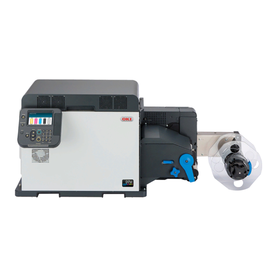
Illustrations Unless otherwise specified, the printer illustrations used herein show the printer with the unwinder mounted. Illustrations may differ from the actual product. Screens The images of the control panel and PC used herein are examples. The images may differ from actual products and screens. -
Page 5: Table Of Contents
Table of Contents Manual Configuration ................2 Reading the Manual .................3 Symbols ........................3 Keys, Buttons, and Symbols ..................3 Illustrations ......................4 Screens ........................4 Inscriptions ......................4 Troubleshooting ..............7 Troubleshooting Solutions Procedure ............8 Paper Jams ....................9 Checking Messages (if a paper jam occurs) ..............9 Removing Jammed Paper .................. - Page 6 Appendix ................101 Specifications ..................102 Major Specifications ....................102 Network Interface Specifications ................104 USB Interface Specifications ..................105 Roll Paper Specifications ..................106 Index ..................115 - 6 -...
-
Page 7: Troubleshooting
Troubleshooting Troubleshooting Solutions Procedure …………………………………… 8 Paper Jams ………………………………… 9 If Messages about Paper Are Displayed …………………………… 24 If Replace Consumables Messages Are Displayed ……………… 25 If Other Messages Are Displayed … 26 Printing Troubles ……………………… 31 - 7 -... -
Page 8: Troubleshooting Solutions Procedure
Troubleshooting Solutions Procedure Troubleshooting Solutions Procedure This chapter describes the procedure for solving problems that occur while using the printer. If you are unable to solve the problem with this procedure, contact the designated customer service center. Is error message or error code displayed on the control panel? If it is displayed If it is not displayed If a paper jam error appears, refer to... -
Page 9: Paper Jams
Paper Jams Paper Jams This section describes the procedure when paper is jammed inside the printer, when part of a piece of paper that is being removed is left inside the printer, or when paper is left inside the printer because an error occurred and caused printing to stop. - Page 10 Paper Jams Message displayed on Error code displayed after Reference Category the display screen pressing the <HELP> button pages Open Unwinder Cover Page 12 Paper Jam Please see HELP for details Open Top Cover Page 12 Paper Jam Please see HELP for details Paper jam Check Fuser and Exit Unit Page 12...
- Page 11 Paper Jams „ Operating the Help screen Press the scroll button Pressing the <HELP> button in the control panel The next page will appear, and solution will display the solution method. You can easily procedure for paper jam will be remove the paper according to the guidance.
-
Page 12: Removing Jammed Paper
Paper Jams Removing Jammed Paper „ Error codes: 380, 381, 382, 386, 389, 391, 631, 637, 638, 639, 7381, 7310, 7306, 7319, 7372, 7311, 7314, 7315 Memo z Refer to the “Setup Guide” regarding the names and functions of parts. Use scissors to cut the jammed paper. - Page 13 Paper Jams Raise the cutter unit lock levers at both Grasp the top cover open lever and ends of the cutter unit. open the top cover. Prepare some newspaper or something to spread on a flat surface on which to place the print cartridge set, as well as some paper so it is not exposed to light.
- Page 14 Paper Jams Turn the two belt locking keys Hold the belt unit handles (blue) on the counterclockwise to release the lock. left and right, and remove the belt unit at an angle. Note z Do not touch the belt surface or damage the belt. Note z Be careful not to touch the nearby terminals while turning the belt locking key.
- Page 15 Paper Jams z Do not touch the belt surface or damage the belt. Note z Be careful not to spill waste toner while removing the belt unit. z Be careful to not pinch your hands or fingers between the handle and the machine while removing the belt unit.
- Page 16 Paper Jams While the paper guide release lever If paper is being output from the is lifted, slide the paper guide in the printer, use scissors to cut it between direction of the arrow to remove it. two labels. Note While pulling the fuser and exit unit locking lever towards you, pull out the z If any paper is jammed, pull it out in the direction...
- Page 17 Paper Jams Hold the fuser and exit unit with both hands and remove it to a level spot. While supporting the fuser and exit unit with one hand, lift up the fuser and exit unit handle. Note z Be careful, the fuser and exit unit is very hot immediately after printing.
- Page 18 Paper Jams Lower the release lever of the fuser and exit unit, open the exit feed cover and Exit feed cover put the fuser and exit unit handle below the exit feed cover. Slowly pull out the paper that is left in the fuser and exit unit in the direction of the arrow.
- Page 19 Paper Jams Lift the fuser and exit unit with both Lift up the fuser and exit unit locking hands and put it into the printer. lever. Push down the fuser and exit unit handle, and firmly push it inside. Confirm that the blue levers in the unwinder are raised, and then remove the cutter unit.
- Page 20 Paper Jams Check for any paper or paper dust that Raise the blue lever and install the has accumulated in the cutter unit, and cutter unit. remove any that has accumulated. Remove any paper that is left in the paper feed path in the unwinder. - 20 -...
- Page 21 Paper Jams Align the positions of the paper guide’s edge ( ① ) and the guide notch on the printer. ① Tilt the belt unit and align the arrow labels (red) on the belt unit and printer to position it, and then open the belt unit handles (blue) on the left and right.
- Page 22 Paper Jams Note z Be careful not to touch the nearby terminals while turning the belt locking key. Note z Be careful to not pinch your hands or fingers between the handle and the machine while installing the belt unit. Turn the two belt locking keys clockwise Put the print cartridge set back into the to lock it.
- Page 23 Paper Jams Close the top cover. Note Close the unwinder cover. z When closing the top cover, there is a risk of pinching your fingers or hands in the top cover or the top cover's support. Press on the top of the top cover to close it.
-
Page 24: If Messages About Paper Are Displayed
If Messages about Paper Are Displayed If Messages about Paper Are Displayed When paper type/size set in the unwinder differs from the printer driver specification, messages, such as "Change paper", will appear, and the ATTENTION lamp will blink. Messages related to paper and error codes, cause of errors and their resolutions, and status of the ATTENTION lamp is described below. -
Page 25: If Replace Consumables Messages Are Displayed
If Replace Consumables Messages Are Displayed If Replace Consumables Messages Are Displayed When the scheduled replacement of consumables approaches, or when the replacement becomes necessary, messages, such as "ABC Near End of Life" and "Install New ABC / ABC Life", will appear, and the ATTENTION lamp will start blinking. -
Page 26: If Other Messages Are Displayed
- [COLOR]: Either yellow, magenta, cyan, black, or white appears. *: White appears only for the Pro1050. - [MENUCOLOR] : Y,M,C,K (Pro1040) / Y,M,C,K,W (Pro1050) - [COVER]: Either top cover or unwinder cover is displayed. - [ERRCODE]/ [CODE]: Detailed numbers of the error are displayed. - Page 27 If Other Messages Are Displayed Message displayed on the Error ATTENTION Reference Causes and Troubleshooting display screen code lamp pages The job was cancelled due to a 7386 Blinking Printing was stopped and the data paper width mismatch was deleted because the paper width To turn off the display, press OK settings were different from those button...
- Page 28 Go to User Manual Trouble in the machine. Shooting to restore operation The warranty is applicable when the product is used with its designated OKI Original consumables. Use caution when choosing other consumables. The entire risk as to the quality and...
- Page 29 If Other Messages Are Displayed Message displayed on the Error ATTENTION Reference Causes and Troubleshooting display screen code lamp pages The data will be deleted due to a 7380 Blinking The position of the white print cartridge spot color order mismatch error. is different from that specified in the Check the print cartridge printer driver.
- Page 30 If Other Messages Are Displayed Message displayed on the Error ATTENTION Reference Causes and Troubleshooting display screen code lamp pages Check Installed Paper 7307 Blinking The mark on the leading edge of the Paper Edge Error paper cannot be detected correctly. Replace the paper, and then press the Press OK Button <OK>...
-
Page 31: Printing Troubles
Printing Troubles Printing Troubles This section describes the possible troubles that may occur while operating the printer, and their solution procedure. Memo z If the problem is not solved using the following methods, contact your designated customer service center. z For problems arising from the applications, contact the application development company. - Page 32 IP address of the printer set in the computer are matching. z If you are using OKI LPR Utility on Windows, check IP address settings in OKI LPR Utility. z Check that IP address is not the same as other devices.
- Page 33 Printing Troubles Printer Troubles Memo z If the problem is not solved using the following explanation, contact your designated customer service center. Reference Symptom Cause Troubleshooting pages Nothing is displayed in the Power supply cord is Switch off the power supply, and Setup Guide display screen panel even after disconnected.
- Page 34 Printing Troubles Reference Symptom Cause Troubleshooting pages A sound is heard from the Glue of the labels accumulated Clean the cutter unit. Page 93 cutter unit when cutting the on the cutter blades inside the paper. cutter unit or paper dust may make the blade rubbed and make a sound.
-
Page 35: Printer Driver Malfunctions
Printing Troubles Printer Driver Malfunctions Memo z If the problem is not solved using the following explanation, contact your designated customer service center. z For problems arising from the applications, contact the application development company. USB Connection Problems Reference Symptom Solution procedure pages Icon of the printer is not created in the [Devices... - Page 36 Printing Troubles Reference Symptom Solution procedure pages Cannot print on specified paper when doing From the print screen of the printer driver on the shared printing. client side, click [Preferences] (or [Properties]), and then, on the [Extend] tab, click [Advanced]. Select [Reduce Size of Spool File], and then set [Settings] to [On] to use it.
- Page 37 Printing Troubles Problems concerning restrictions of OS „ Limitations regarding Windows 10/Windows 8.1/Windows 8/Windows 7/ Windows Server 2016/ Windows Server 2012 R2/Windows Server 2012/ Windows Server 2008 R2/Windows Server 2008 Items Symptom Causes and Troubleshooting Printer driver The [User Account When starting installer or utility, the [User Account Control] Control] dialog appears.
-
Page 38: Print Quality Is Poor
Printing Troubles Print Quality Is Poor Memo z If the problem is not solved using the following methods, contact your designated customer service center. Reference Symptom Cause Troubleshooting pages White stripe in LED head is unclean. Wipe LED head with a soft tissue Page 89 perpendicular direction. - Page 39 Printing Troubles Reference Symptom Cause Troubleshooting pages Printing is blurred in The paper is too damp or too dry. Use paper that has been stored User's Guide some parts. White dots at appropriate temperature and appear when printing humidity. solid colors. [Transfer Setting] is not properly If white dots appear in cyan transfer, User’s Guide...
- Page 40 Printing Troubles Reference Symptom Cause Troubleshooting pages Stripes or dots appear In the case of a cycle length of Wipe it lightly with a soft tissue paper. Page 55 periodically in horizontal about 94 mm, the print cartridge If there are dents, replace the print direction.
- Page 41 Printing Troubles Reference Symptom Cause Troubleshooting pages Bold lines appear in Type and thickness setting of If a line is printed from the second User's Guide horizontal direction. paper is inappropriate. page with black & white print, set the [Media Weight] in [Paper settings] of the printer driver to an appropriate value.
- Page 42 Printing Troubles Reference Symptom Cause Troubleshooting pages Does not print with color Low toner. Replace the print cartridge. Page 55 shades as you thought. Setting of [Black Finish] is not In the [Black Finish] of printer driver, User's Guide matching with the application. select [True Black (K)] or [Composite Black (CMYK)].
- Page 43 Printing Troubles Reference Symptom Cause Troubleshooting pages Afterimages are The print quality setting is not Set [Smooth] in [Screen] for the print User’s Guide appearing. appropriate. quality settings in the printer driver. Paper feed direction Distorted images occur The toner is misaligned. There are three types of solutions.
- Page 44 Printing Troubles Reference Symptom Cause Troubleshooting pages The position that The belt has stretched. Adjust the registration before you User’s Guide printing starts on start printing, and install the printer the leading edge is in a room that has humidity that is as misaligned.
- Page 45 Printing Troubles Reference Symptom Cause Troubleshooting pages Pages are cut on a Last of the paper was detected. Replace the paper with a new roll different page than the of paper. When reprinting, paper specified page. is output from the page where the error occurred up to the cut page.
-
Page 46: Paper Feed Is Poor
Printing Troubles Paper Feed Is Poor Memo z If the problem is not solved using the following methods, contact your designated customer service center. Reference Symptom Cause Troubleshooting pages Paper jam occurs frequently. Device is tilted. Install on a stable and a flat surface. - Page 47 Printing Troubles Reference Symptom Cause Troubleshooting pages Paper jam occurs frequently. The positions of the machine Align the position of the sensor User’s Guide and the unwinder sensors do with the paper. not match. Labels are missing from the roll Load a suitable roll of paper.
- Page 48 Printing Troubles Reference Symptom Cause Troubleshooting pages The space between labels is not The position of the cut is Readjust the cutting position. User’s Guide cut; the labels are cut. misaligned. The leading edge of the label Labels cannot be used if the Page 106 and the black mark positions leading edge of the label and the...
-
Page 49: Maintenance
Maintenance Checking Service Life and Remaining Amounts of Consumables …………… 50 Replacing Consumables ……………… 51 Printer Maintenance …………………… 73 - 49 -... -
Page 50: Checking Service Life And Remaining Amounts Of Consumables
Checking Service Life and Remaining Amounts of Consumables Checking Service Life and Remaining Amounts of Consumables You can check the service life and remaining quantities of the print cartridge, belt unit, fuser and exit unit, and waste toner box. Press the scroll button ▲... -
Page 51: Replacing Consumables
Replacing Consumables Replacing Consumables This section describes the service life and replacement method of consumables. About the Service Life of Consumables Guidelines for replacement of consumables are as follows. *Periodically replaced parts are parts that need a service representative. z Print Cartridge (CMYK) When A6 size documents with print density of 20% are printed continuously, the printable pages... - Page 52 Replacing Consumables ‰ Only for Pro1050 z Print cartridge (White) The print cartridge (white) is for the Pro1050 only. It cannot be used on the Pro1040. When A6 size documents with print density of 20% are printed continuously, the printable pages is about 4,500.
-
Page 53: When The Replacement Period Is Approaching
Replacing Consumables When the Replacement Period Is Approaching When the scheduled replacement of consumables approaches, the following message will appear and the ATTENTION lamp will blink. Replace consumables when "Install New ..." appears in the message. Pressing the <HELP> button on the control panel will display the replacement procedure. You can easily replace the consumables according to the guidance. -
Page 54: Replacing Print Cartridges
Replacing Consumables Replacing Print Cartridges z Toner spilled on the floor should be WARNING carefully wiped up with a wet cloth so the toner does not scatter around. z Do not put toner or print cartridges z Gently wipe the dirt stuck to the brown in fire. - Page 55 Replacing Consumables Replacing print cartridges Remove the new print cartridge from the packing bag, and then shake it Example) For the yellow (Y) print cartridge vertically and horizontally. Grasp the top cover open lever and open the top cover. Check the position of the print cartridge to replace, by the text and color of the label.
- Page 56 Replacing Consumables Close the top cover. Note z When closing the top cover, there is a risk of pinching your fingers or hands in the top cover or the top cover's support. Press on the top of the top cover to close it. z There is a risk of pinching your fingers or hands if you hold the LED head while closing the top cover.
-
Page 57: Replacing The Belt Unit And 2Nd Transfer Roller
Replacing Consumables Replacing the Belt Unit and 2nd Transfer Roller Replacing the Belt Unit and 2nd Remove the print cartridge set. Transfer Roller A new 2nd transfer roller is supplied with the new belt unit in the same package. Also, a new waste toner box is mounted inside the belt unit. - Page 58 Replacing Consumables Turn the two belt locking keys Hold the belt unit handles (blue) on the counterclockwise to release the lock. left and right, and remove the belt unit at an angle. Note z Do not touch the belt surface or damage the belt. Note z Be careful not to touch the nearby terminals while turning the belt locking key.
- Page 59 Replacing Consumables Place the removed belt unit levelly. ❷ Note z Be careful not to spill waste toner while removing the belt unit. z Be careful to not pinch your hands or fingers between the handle and the machine while removing the belt unit.
- Page 60 Replacing Consumables Hold the 2nd transfer roller unit ( ① ) Remove the 2nd transfer roller from its knob (blue) and remove it. packaging. Note z Do not touch the roller part (sponge part) of the 2nd transfer roller. Touching it damages the surface of the roller, which degrades print quality.
- Page 61 Replacing Consumables Remove the new belt unit from its packaging. Note z Do not touch the belt surface or damage the belt. Note z Be careful, the fuser and exit unit is very hot immediately after printing. - 61 -...
- Page 62 Replacing Consumables Tilt the belt unit and align the arrow labels (red) on the belt unit and printer to position it, and then open the belt unit handles (blue) on the left and right. Note z Be careful to not pinch your hands or fingers between the handle and the machine while installing the belt unit.
- Page 63 Replacing Consumables Close the top cover. Note z Be careful not to touch the nearby terminals while turning the belt locking key. Note Put the print cartridge set back into the z When closing the top cover, there is a risk of printer.
-
Page 64: Replacing Waste Toner Boxes
Replacing Consumables Replacing Waste Toner Boxes Replacing Waste Toner Boxes Prepare some newspaper or something to spread on a flat surface on which to place the belt unit. Grasp the top cover open lever and open the top cover. Turn the two belt unit locking keys counterclockwise to release the lock. - Page 65 Replacing Consumables Hold the belt unit handles (blue) on the left and right, and remove the belt unit at an angle. Note z Do not touch the belt surface or damage the belt. ❷ Note z Be careful not to spill waste toner while removing the belt unit.
- Page 66 Replacing Consumables Remove the waste toner box from the back of the belt unit. Note z Place the belt unit on a flat surface, as shown in the diagram above. Do not stand it on its side. z Do not touch the belt surface or damage the belt. - 66 -...
- Page 67 Replacing Consumables Insert the new waste toner box into the belt unit, and firmly push it inside. Note z Do not tilt the waste toner box. Waste toner could leak out and stain your clothes or hands. Remove the new waste toner box from its packaging.
- Page 68 Replacing Consumables Tilt the belt unit and align the arrow labels (red) on the belt unit and printer to position it, and then open the belt unit handles (blue) on the left and right. Note z Be careful to not pinch your hands or fingers between the handle and the machine while installing the belt unit.
- Page 69 Replacing Consumables Put the print cartridge set back into the Please support recycling of the used printer. waste toner boxes. Note z Do not disassemble the waste toner box, and do not force it open. Doing so may cause toner to spray out, to be inhaled, or to soil your clothing and hands.
-
Page 70: Replacing The Fuser And Exit Unit
Replacing Consumables Replacing the Fuser and Exit Unit Replacing the Fuser and Exit Unit While pulling the fuser and exit unit locking lever towards you, pull out the fuser and exit unit. CAUTION There is a risk of burns. Note Work carefully because the fuser and exit unit is very hot. - Page 71 Replacing Consumables While supporting the fuser and exit unit Remove the new fuser and exit unit with one hand, lift up the fuser and exit from its packaging. unit handle. Pull the fuser and exit unit locking lever on the new fuser and exit unit towards yourself, and lift the fuser and exit unit handle.
- Page 72 Replacing Consumables Push down the fuser and exit unit Lift up the fuser and exit unit locking handle, and firmly push it inside. lever. Please support recycling of the used fuser and exit units. Note z Do not disassemble the fuser output unit, and do not force it open.
-
Page 73: Printer Maintenance
Printer Maintenance Printer Maintenance This section describes how to clean the various parts of the printer. Things to Prepare Prepare the following things for cleaning the various parts of the printer. z Wiper (or equivalent product) z Cleaning fluid (isopropyl alcohol) z Water or neutral cleanser z Cotton swabs Cleaning Schedule... -
Page 74: Cleaning The Unwinder
Printer Maintenance Cleaning the Unwinder Clean the Inside of the Unwinder This section describes how to clean the various Press and hold the <POWER> button parts of the unwinder. for approximately 1 second to switch off the power supply. Cleaning the Surfaces of the Unwinder Note z Do not use Benzene or thinner as it may damage plastic... - Page 75 Printer Maintenance Remove the flange. Use Wiper moistened with cleaning fluid (isopropyl alcohol) to wipe any dirt off the sides of the flange and Side-Guide- 8Inch. Flange Turn the roll paper holder knob in the direction of the arrow to narrow the Side surface shaft of the roll paper holder.
- Page 76 Printer Maintenance While restraining the tension bar with Lower the unwinder cover open lever to one hand, use Wiper moistened with open the unwinder cover. cleaning fluid (isopropyl alcohol) to wipe, in one direction, the dirt off the tension bar ( ① ). Use the hand that is restraining the tension bar to rotate it ( ②...
- Page 77 Printer Maintenance If there are scraps of paper or glue If there are scraps of paper or glue from the labels on the sheet guide, use from labels on the ends of the sheet Wiper moistened with cleaning fluid guide, undo the screw and remove the (isopropyl alcohol) to wipe it off.
- Page 78 Printer Maintenance Remove the F0 roller unit. Use Wiper moistened with cleaning fluid (isopropyl alcohol) to wipe, in one direction, the dirt off the sensor cover (lower). As you rotate the gears with one hand, use Wiper moistened with cleaning fluid (isopropyl alcohol) to clean the top and bottom rollers on the F0 roller unit by wiping in just one direction.
-
Page 79: Cleaning The Printer
Printer Maintenance Cleaning the Printer Cleaning the Inside of the Printer This section describes how to clean the various Press and hold the <POWER> button parts of the printer. for approximately 1 second to switch off the power supply. Cleaning Device Surfaces Note z Do not use Benzene or thinner as it may damage plastic parts and coating. - Page 80 Printer Maintenance Remove the print cartridge set. Turn the two belt locking keys counterclockwise to release the lock. Place the removed print cartridge, and cover it with paper so it is not exposed to light. Note Prepare some newspaper or something z Be careful not to touch the nearby terminals while to spread on a flat surface on which to turning the belt locking key.
- Page 81 Printer Maintenance Hold the belt unit handles (blue) on the left and right, and remove the belt unit at an angle. Note z Do not touch the belt surface or damage the belt. ❷ Note z Be careful not to spill waste toner while removing the belt unit.
- Page 82 Printer Maintenance Place the removed belt unit levelly. Pull up the paper guide release lever. Paper guide release lever Note z Place the belt unit on a flat surface, as shown in the diagram above. Do not stand it on its side. While the paper guide release lever is lifted, slide the paper guide in the direction of the arrow to remove it.
- Page 83 Printer Maintenance Use Wiper moistened with cleaning fluid If the rollers and feed surface of the (isopropyl alcohol) to wipe the dirt off feed unit on the bottom of the paper the F4 roller, F3 roller, F2 roller, and guide are dirty, gently wipe them clean feed surface of the paper guide.
- Page 84 Printer Maintenance Open the sensor cover. While pulling the fuser and exit unit locking lever towards you, pull out the fuser and exit unit. Note z Do not apply excessive force to the sensor cover. Note Sensor cover z Be careful, the fuser and exit unit is very hot immediately after printing.
- Page 85 Printer Maintenance While supporting the fuser and exit unit with one hand, lift up the fuser and exit unit handle. Note z Be careful, the fuser and exit unit is very hot immediately after printing. Lower the release lever and open the exit feed cover.
- Page 86 Printer Maintenance Use Wiper moistened with cleaning fluid Push down the fuser and exit unit (isopropyl alcohol) to wipe the dirt off handle, and firmly push it inside. exit 1 roller/exit 2 roller/paper feed surface. Exit 1 roller * Roller on fuser side of fuser and exit unit Exit 2 roller...
- Page 87 Printer Maintenance Align the positions of the paper guide’s Firmly push the paper guide all the way edge ( ① ) and the guide notch on the in the direction of the arrow, and then printer. push on the A position to lock it. ①...
- Page 88 Printer Maintenance Turn the two belt locking keys clockwise to lock it. Note z Be careful not to touch the nearby terminals while turning the belt locking key. Note z Be careful to not pinch your hands or fingers between the handle and the machine while installing the belt unit.
- Page 89 Printer Maintenance Cleaning LED Heads Put the print cartridge set back into the printer. Clean the LED heads if the print results are blurry, white stripes appear, or if text is bleeding. Clean the LED heads if the printed results show lengthwise white lines, if images are omitted lengthwise, or if there is bleeding around text.
- Page 90 Printer Maintenance Check if the LED heads are dirty Close the top cover. because toner or something is on them. Note z When closing the top cover, there is a risk of pinching your fingers or hands in the top cover or the top cover's support.
-
Page 91: Cleaning The Fuser Unit
Printer Maintenance Cleaning the Fuser Unit Press the scroll button ▲ or ▼. This section describes how to clean the various parts of the fuser unit. This procedure is for cleaning the inside of the fuser unit. Streaks may appear when printing, particularly after changing the paper width from narrow to wide, because of the traces (paper dust etc.) left along the width of the paper. - Page 92 Printer Maintenance You cannot reuse cleaning paper. Dispose of the cleaning paper that you print. After cleaning is finished, remove the cleaning paper, load new paper, and start printing. - 92 -...
-
Page 93: Cleaning The Cutter Unit
Printer Maintenance Cleaning the Cutter Unit Do not dismantle any parts other than those specified in this procedure. Malfunctions could occur. Daily maintenance You should do daily maintenance to keep the machine in good condition as you use it. Check the condition of the machine when you start and stop using it, and clean it if needed. Refer to “Printer Maintenance”... - Page 94 Printer Maintenance Turn off the power to the printer. Press and hold the <POWER> button for approximately 1 second. “Shutting down. Please wait. Printer will turn off automatically.” appears on the control panel and the LED lamp on the <POWER> button flashes at one second intervals.
- Page 95 Printer Maintenance Remove any paper left in the cutter unit. If there is paper left inside the cutter unit after you have removed it, remove that paper. Hold the handle of the cutter to remove the cutter unit. Left over paper cutter unit sensor cover (upper)
- Page 96 Printer Maintenance Disassemble the cutter unit. Note Remove the 3 screws. z There are blades inside the cutter unit for cutting roll paper. Do not touch the blades of the cutter with your hands. There is a risk of injury. Remove any paper left inside the cutter unit.
- Page 97 Printer Maintenance Clean the F1 roller unit. Note The F1 roller unit feeds paper through z There are blades inside the cutter unit for cutting the cutter unit. When cleaning the roll paper. Do not touch the blades of the cutter with your hands.
- Page 98 Printer Maintenance Assemble the cleaned cutter unit. Use a flathead screwdriver to tighten the 3 screws. Note z There are blades inside the cutter unit for cutting roll paper. Do not touch the blades of the cutter with your hands. There is a risk of injury. Assemble the F1 roller unit.
- Page 99 Printer Maintenance Lower the cutter unit lock levers at both ends of the cutter unit. Close the unwinder cover. The procedure to clean the cutter's blades is complete. - 99 -...
- Page 100 Printer Maintenance - 100 -...
-
Page 101: Appendix
Appendix Specifications …………………………… 102 - 101 -... -
Page 102: Specifications
Windows Server 2012 R2/Windows Server 2012/Windows Server 2008 R2/ Windows Server 2008 Refer to the operating environment for details. Printing method Pro1040: Full-color dry-type electrophotographic method using 4 consecutive digital LED heads Pro1050: Full-color dry-type electrophotographic method using 5 consecutive digital LED heads... - Page 103 Specifications Consumables and maintenance Consumables: Print cartridge, belt unit (3-piece set of belt, waste toner box, parts and 2nd transfer roller), waste toner box, fuser and exit unit Maintenance products: Cutter unit, F0 roller unit, paper guide, feed unit Operating sound When operating 57 dBA (Reference value) (noise level)
-
Page 104: Network Interface Specifications
Specifications Network Interface Specifications z <Basic specifications> Network protocol • TCP/IP protocols • EtherTalk protocols z <Connectors> 1000BASE-T/100 BASE-TX/10 BASE-T (automatic switching, simultaneous usage not possible) Note z 1000BASE-T is disabled in the default factory settings. To use 1000BASE-T, do the following settings on the control panel. [Admin Setup] >... -
Page 105: Usb Interface Specifications
Specifications USB Interface Specifications z <Basic specifications> USB (Hi-Speed USB compatible) z <Connectors> B receptacle (female) upstream port z <Cables> USB 2.0 specification cable at 5 m or less (2 m or less recommended) (Use shielded cables.) z <Transmission modes> Full speed (maximum 12 Mbps ±0.25%) High speed (maximum 480 Mbps ±0.05%) z <Power control>... -
Page 106: Roll Paper Specifications
Specifications Roll Paper Specifications „ Continuous paper (normal printing) Printing range Outside winding: Printable surface faces out. Winding direction Inside winding: Printable surface faces in Paper weight 0.07 to 0.25 mm (0.003 to 0.0098 inches) Roll core Inner diameter: 76.2 mm (3 inches) Outer diameter 203.2 mm (8 inches) or less Other... - Page 107 Specifications „ Continuous paper (printing on large size paper) Printing range Outside winding: Printable surface faces out. Winding direction Inside winding: Printable surface faces in Paper weight 0.07 to 0.25 mm (0.003 to 0.0098 inches) Core Inner diameter: 76.2 mm (3 inches) Outer diameter 203.2 mm (8 inches) or less Other...
- Page 108 Specifications „ Continuous paper (with black marks) Printing range Black mark Outside winding: Printable surface faces out. Winding direction Inside winding: Printable surface faces in Paper weight 0.07 to 0.25 mm (0.003 to 0.0098 inches) Core Inner diameter: 76.2 mm (3 inches) Outer diameter 203.2 mm (8 inches) or less Other...
- Page 109 Specifications „ Die-cut label paper Liner 4R1 or greater Printing range Outside winding: Printable surface faces out. Winding direction Inside winding: Printable surface faces in Paper weight 0.07 to 0.25 mm (0.003 to 0.0098 inches) Core Inner diameter: 76.2 mm (3 inches) Outer diameter 203.2 mm (8 inches) or less Other...
- Page 110 Specifications „ Die-cut label paper (with black marks) Liner 4R1 or greater Black marks correspond to the leading edge of label Printing range Black mark Outside winding: Printable surface faces out. Winding direction Inside winding: Printable surface faces in Paper weight 0.07 to 0.25 mm (0.003 to 0.0098 inches) Core Inner diameter: 76.2 mm (3 inches)
- Page 111 Specifications „ Full sheet labels (normal printing) Liner Printing range Outside winding: Printable surface faces out. Winding direction Inside winding: Printable surface faces in Paper weight 0.07 to 0.25 mm (0.003 to 0.0098 inches) Core Inner diameter: 76.2 mm (3 inches) Outer diameter 203.2 mm (8 inches) or less Other...
- Page 112 Specifications „ Full-sheet labels (printing on large size paper) Liner Printing range Outside winding: Printable surface faces out. Winding direction Inside winding: Printable surface faces in Paper weight 0.07 to 0.25 mm (0.003 to 0.0098 inches) Core Inner diameter: 76.2 mm (3 inches) Outer diameter 203.2 mm (8 inches) or less Other...
- Page 113 Specifications „ Full-sheet label paper (with black marks) Liner Printing range Black mark Outside winding: Printable surface faces out. Winding direction Inside winding: Printable surface faces in Paper weight 0.07 to 0.25 mm (0.003 to 0.0098 inches) Core Inner diameter: 76.2 mm (3 inches) Outer diameter 203.2 mm (8 inches) or less Other...
- Page 114 Specifications - 114 -...
-
Page 115: Index
Index - 115 -... - Page 116 Cleaning ............ 73 Specifications ........... 102 Cutter Unit ......... 93 Fuser Unit .......... 91 Printer..........79 Troubleshooting solutions procedure....8 Unwinder ........... 74 Consumables ..........51 Service life........50, 51 Help screen operations ........ 11 Messages ........9, 24, 25, 26 Confirming ........... 9 Paper jam............
- Page 117 - 117 -...
- Page 118 Oki Data Corporation 4-11-22 Shibaura, Minato-ku,Tokyo 108-8551, Japan May 2019 47232102EE Rev3 https://www.oki.com/printing/...
Need help?
Do you have a question about the Pro1040 and is the answer not in the manual?
Questions and answers