Table of Contents
Advertisement
EURO 280
Installation Manual
For Castle/Pyronix Technical Support please call:
08456 434 999 (local rate) or:
01709 535 225
or visit:
www.pyronix.com
When calling Technical Support, please have ready
your software version number. This will enable the
correct advice to be given for your panel and can be
found in the engineer menu under 'software
revisions'.
RINS1862-5
Security Grade (SG) 3
Environment Class (EC) II
(Different case sizes available)
For use with EURO 280 software: Version 9.51 or
above
Advertisement
Table of Contents

Related Manuals for HIKVISION Castle/Pyronix Euro 280


Summary of Contents for HIKVISION Castle/Pyronix Euro 280
- Page 1 Security Grade (SG) 3 Environment Class (EC) II EURO 280 Installation Manual (Different case sizes available) For Castle/Pyronix Technical Support please call: For use with EURO 280 software: Version 9.51 or 08456 434 999 (local rate) or: above 01709 535 225 or visit: www.pyronix.com When calling Technical Support, please have ready...
-
Page 2: Table Of Contents
EURO 280 Installation Manual C o n t e n t s P a g e 1. System Overview ......................................... 3 1.1 System Overview ........................................3 1.2 The Devices ..........................................4 1.3 EURO 280 Input Mapping Table: ................................... 6 1.4 EURO 280 Output Mapping Table:..................................7 2. -
Page 3: System Overview
1 . S y s t e m O v e r v i e w The EURO 280 is a wired control panel that can have a maximum of 280 inputs. It is also compatible with Two-Way Enforcer wireless peripherals using the EURO-ZEM32-WE (wireless expander). 1.1 System Overview PANEL: EURO 280... -
Page 4: The Devices
EURO 280 Installation Manual 1.2 The Devices 1.2.1 The EURO 280 Bus Diagram All EURO peripherals; LCD keypads, readers, expanders etc. are connected via the D1-, D2+, D3 and D4 terminals. This is an example of what a typical Euro 280 bus may look like. General Principles: NOTE 1: No alarm system cable should be run with other cables carrying AC or... - Page 5 1.2.2 RS-485 Wiring Wiring Format Cable type Screened Cable Bus range (m) Daisy Chain Range Star Range 4 core alarm cable 300m Use when bus located near 6 core alarm cable 230VAC mains doubling D1 (0V) and 1000m power line D2 (12V) Twisted pair 1000m...
-
Page 6: Euro 280 Input Mapping Table
EURO 280 Installation Manual 1.3 EURO 280 Input Mapping Table: DEVICES Address Input Numbers EURO 280 PCB 9-16 17-24 25-32 33-40 41-48 49-56 EURO-ZEM8 / EURO-ZEM8+ / EURO-ZEM8+PSU / EURO-ZEM32-WE 57-64 65-72 73-80 81-88 89-96 97-104 105-112 113-120 121-128 129-136 137-144 145-152 153-160... -
Page 7: Euro 280 Output Mapping Table
1.4 EURO 280 Output Mapping Table: DEVICES Address Output Numbers EURO 280 PCB ATE Outputs (using communication ribbon) Ribbon 1-16 1-16 1-16 1-16 1-16 1-16 1-16 EURO-OEM8R8T / EURO-OEM16R+PSU 1-16 1-16 1-16 1-16 1-16 1-16 1-16 1-16 1-16 EURO-ZEM8+ / EURO-ZEM8+PSU EURO-LCDPZ EURO-LCDPZ / EURO PROXI / EURO PROXE (Continued overleaf) -
Page 8: Installation
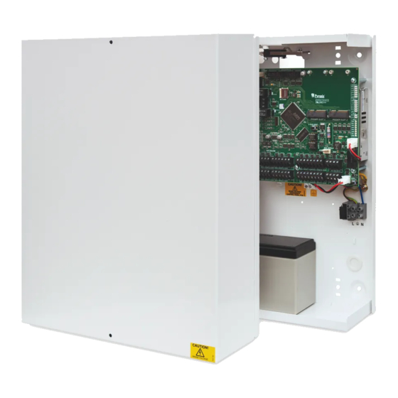
EURO 280 Installation Manual 2 . I n s t a l l a t i o n 1. Unscrew and remove the cover of the EURO 280 control panel (Figure 1). 2. Install the supplied stand offs if needed before you mount the metal case to the wall (Figure 3). Figure 1. -
Page 9: The Printed Circuit Board
T h e P r i n t e d C i r c u i t B o a r d 12] 0V & 17V connection 1] Ethernet Status LEDs Connects the 0V and 17V supply from the power supply 2] Case Tamper transformer (DC-IN). -
Page 10: Technical Specification
EURO 280 Installation Manual 2.3 Technical Specification Programmable Outputs Ratings Normal State Active State Output 1 Relay, 3A, max 30V Normally Closed Normally Open Output 2 Relay, 3A, max 30V Normally Closed Normally Open Speaker 16 ohms No tones Repeat RKP tones & internal sounder Strobe Output 500mA Bell Output... -
Page 11: Important Installation Notes
EURO PCB Current Consumption Environmental Quiescent 75-90mA Operational -10°C to +40°C, Certified User Code and Tag Guessing Storage -20°C to +60°C 4-digit codes 10,000 Humidity 6-digit codes 100,000 Dimensions Disallowed codes None Metal Casing (L) 390 x 305 x 100mm All codes Weight: 6kg According to EN50131-3:2009 Annex B... -
Page 12: Communication Ate Loom
EURO 280 Installation Manual 2.2 Communication ATE Loom ATE low power outputs are programmed in the engineer menu: “CHANGE OUTPUTS->Endstation Outputs”. Purple (ATE Output 8: Mains Fail (0052)) Light Grey (ATE Output 10: Test ATS (0064)) White (ATE Output 9: Global Fault 2 (0056)) Black (ATE Output 7: Confirmed Any (0006)) Brown (ATE Output 4: Final Set All (0004)) Red (0V) -
Page 13: Engineer Keypad Connection
Connects to DC-IN (DC-IN) (See Fig. A) MAINS IN: VIEW: PSU TERMINALS (Underneath Main PCB) Panel Power Supply Input Nominal Range Mains Supply Voltage AC 230V AC at 50Hz -15% +10% PSU Rating 51VA 18.5V at 2.5A Panel Power Supply Output Nominal Range Output Voltage... -
Page 14: Input Connections
EURO 280 Installation Manual NOTE: Before an Engineer keypad is enabled, it should be addressed as an additional keypad on the control panel before operation. See page: 19 for adding keypads to the control panel. 3 . I n p u t C o n n e c t i o n s Here are some examples of a typical connection to a wired detector, for grade 2 and grade 3 respectively: Control Panel Page: 14... -
Page 15: Default Grade 2 Deol (Double End Of Line) Input Wiring
3.1 Default Grade 2 DEOL (Double End of Line) Input Wiring The above wiring example shows the connections for a Grade 2 KX15DQ PIR detector. 3.2 Grade 3 Mask/Fault Input Wiring The above wiring example shows the connections for a Grade 3 KX15DTAM detector. Page: 15... -
Page 16: Output (Pgm) Connections
EURO 280 Installation Manual 4 . O u t p u t ( P G M ) C o n n e c t i o n s 4.1 Negative Applied Wiring Normal State: NC Active State: 0V Relay Rated at 2A Place the jumper / link in the position shown to set the... -
Page 17: External Sounder Connections
5 . E x t e r n a l S o u n d e r C o n n e c t i o n s 5.1 Grade 3 External Sounder Wiring Pyronix Grade 3 External Sounders: Deltabell Plus Deltabell X Invincibell Plus Invincibell X... -
Page 18: Grade 2 External Sounder Wiring
EURO 280 Installation Manual 5.3 Grade 2 External Sounder Wiring Pyronix Grade 2 External Sounders: Deltabell E Invincibell E Page: 18... -
Page 19: Connecting The Euro Peripherals
6 . C o n n e c t i n g t h e E U R O P e r i p h e r a l s 6.1 Connecting the LCD Keypad (EURO-LCDPZ) The EURO-LCDPZ keypad is used for programming and user operation. - Page 20 EURO 280 Installation Manual 6.1.2 Addressing the EURO-LCDPZ Keypad Addressing Hold the key for more than 5 seconds. 'SECURITY CODE' will be displayed. Enter '2000' The default address is '00'. Enter the required Address and press Press to exit. You must now address this from the menu "ASSIGN KEYPADS/READERS".
- Page 21 6.1.5 Connecting the EURO-LCDPZ Keypad Inputs (Grade 3) EURO-LCDPZ Keypad PCB The above wiring example shows the connections for a Grade 3 KX15DTAM PIR. 6.1.6 Connecting the Outputs (To EURO-LCDPZ) EURO-LCDPZ Keypad PCB Page: 21...
-
Page 22: Connecting The Internal Tag Reader (Euro-Proxi - Eur-107)
EURO 280 Installation Manual 6.2 Connecting the Internal Tag Reader (EURO-PROXI – EUR-107) The Internal Tag Reader can have 2 inputs connected. It can be used as a Set, Unset, Entry control or Access Control device. See the reader installation manual for the LED and button explanations. NOTE: The total number of readers that can be installed on the EURO 280 is 29. - Page 23 6.2.3 Adding the Internal Tag Reader (From the Engineer Menu) Enter the engineer menu and scroll to 'ASSIGN KEYPADS/READERS' and press . Please see the Programming Manual for more information. 6.2.4 Connecting the Internal Tag Reader Inputs The above wiring example shows the connections for a Grade 2 KX15DQ PIR. NOTE: The resistance values are fixed to 4K7 Alarm and 2K2 Tamper in the EURO-PROXI.
-
Page 24: Connecting The External Proximity Reader (Euro-Proxe - Euro-108X)
EURO 280 Installation Manual 6.3 Connecting the External Proximity Reader (EURO-PROXE - EURO-108X) The External Proximity Reader can be used as either a Set, Unset, Entry Control or Access Control device. NOTE: See the reader installation manual for the LED and button explanations. NOTE: The total number of readers that can be installed on the EURO 280 is 7. - Page 25 6.3.3 Adding the External Tag Reader (From the Engineer Menu) Enter the engineers menu and scroll to 'ASSIGN KEYPADS/READERS' and press . Please see the Programming Manual for more information. 6.3.4 Connecting a Mag Lock and a Request to Exit Button to the External Tag Reader The diagram show the relay mag lock control switching positive and shows a normally open request to exit button, and takes “0V”...
- Page 26 EURO 280 Installation Manual 6.3.6 Using the External Tag Reader for Arming and Entry Control 6.3.7 Using the Request to Exit button 6.3.8 Using the External Tag Reader Disarming Page: 26...
-
Page 27: Connecting The Zone Expander Module (Euro-Zem8)
6.4 Connecting the Zone Expander Module (EURO-ZEM8) 6.4.1 The EURO-ZEM8 Expander EURO-ZEM8 The EURO-ZEM8 is an input expander that supports 8 inputs (not inertia). It also supports NC (normally closed), DEOL, SEOL input, and 3 Resistor (Grade 3) configurations. The EURO 280 will support up to 30 x Zone Expander Modules. - Page 28 EURO 280 Installation Manual 6.4.4 Addressing the EURO-ZEM8 (From the Expander) Switch Switch Address Address 6.4.5 Adding the EURO-ZEM8 (From the Engineer Menu) Go to 'INSTALL ZEM?' and press . Please see the Programming Manual for more information. 6.4.6 Wiring Inputs on the EURO-ZEM8 (Normally Closed) Page: 28...
- Page 29 6.4.7 Wiring Inputs on the EURO-ZEM8 (DEOL: Grade 2) The above wiring example shows the connections for a Grade 2 KX15DQ PIR. 6.4.8 Wiring Inputs on the EURO-ZEM8 (3EOL: Grade 3) The above wiring example shows the connections for a Grade 3 KX15DTAM PIR. Page: 29...
-
Page 30: Connecting The Zone Expander Module With 4 Pgms (Euro-Zem8+)
EURO 280 Installation Manual 6.5 Connecting the Zone Expander Module with 4 PGMs (EURO-ZEM8+) EURO-ZEM8+ The EURO-ZEM8+ is an input expander that supports 8 inputs and 4 outputs. It also supports NC (normally closed), DEOL, SEOL input and 3 Resistor (Grade 3) configurations. - Page 31 6.5.2 EURO-ZEM8+ Input Configuration 6.5.3 Addressing the EURO-ZEM8+ NOTE: The addressing is done by headers that represent the address. For example: If a header is placed on 00, and 0, the address is 0. If a header is placed on 00, and 9, the address is 9. If a header is placed on 20, and 3, the address is 23 etc.
- Page 32 EURO 280 Installation Manual 6.5.5 Wiring Inputs on the EURO-ZEM8+ (Normally Closed) The above wiring example shows the normally closed connection for a KX15DQ PIR. 6.5.6 Wiring Inputs on the EURO-ZEM8+ (DEOL - Grade 2) The above wiring example shows the connections for a Grade 2 KX15DQ PIR. Page: 32...
- Page 33 6.5.7 Wiring Inputs on the EURO-ZEM8+ (Mark/Fault - Grade 3) The above wiring example shows the connections for a Grade 3 KX15DTAM PIR. 6.5.8 Output Wiring on the EURO-ZEM8+ Normal State: 12V Active State: 0V Max Current: 100mA Page: 33...
-
Page 34: Connecting The Zone Expander Module With Psu (Euro-Zem8+Psu)
EURO 280 Installation Manual 6.6 Connecting the Zone Expander Module with PSU (EURO-ZEM8+PSU) EURO-ZEM8+PSU The EURO-ZEM8+ is an input expander that supports 8 inputs and 4 PGMs and has a built in 2.5A power supply. It also supports NC (normally closed), DEOL input and 3 Resistor (Grade 3) configurations. - Page 35 6.6.2 EURO-ZEM8+PSU Input Configuration Input Resistance 1k / 1k DEOL Range 4k7 / 2k2 DEOL Range 4k7 / 4k7 DEOL Range Normal (closed state) 0k5 to 1k4 1k4 to 2k9 3k7 to 8k3 Burglary Alarm 1k5 to 5k9 4k2 to 7k8 8k4 to 10k2 Fault 6k to 8k1...
- Page 36 EURO 280 Installation Manual 6.6.5 Wiring Inputs on the EURO-ZEM8+PSU (Normally Closed) The above wiring example shows the normally closed connections for a KX15DQ PIR. 6.6.6 Wiring Inputs on the EURO-ZEM8+PSU (DEOL: Grade 2) The above wiring example shows the connections for a Grade 2 KX15DQ PIR. Page: 36...
- Page 37 6.6.7 Wiring Inputs on the EURO-ZEM8+PSU (DEOL: Grade 3) The above wiring example shows the connections for a Grade 3 KX15DTAM PIR. 6.6.8 Output Wiring on the EURO-ZEM8+PSU Page: 37...
-
Page 38: Connecting The Enforcer Wireless Zone Expander Module (Euro-Zem32-We)
EURO 280 Installation Manual 6.7 Connecting the Enforcer Wireless Zone Expander Module (EURO-ZEM32-WE) EURO-ZEM32-WE The EURO-ZEM32-WE is a wireless input expander that supports Two Way Wireless Enforcer technology. Each expander will allow 32 wireless inputs. The first expander on the bus will allow 32 wireless keyfobs and 2 wireless bells. - Page 39 Addressing Example: Having 96 wireless inputs on the EURO 280 EURO-ZEM32-WE: DEVICE A This expander will learn all 32 wireless keyfobs and 2 wireless bells (address 0). Address 0 = 8 wireless inputs (Inputs 9-16) Address 1 = 8 wireless inputs (Inputs 17-24) ...
-
Page 40: Connecting The Output Expander Module (Euro-Oem8R8T)
EURO 280 Installation Manual 6.8 Connecting the Output Expander Module (EURO-OEM8R8T) EURO-OEM8R8T The EURO-OEM8R8T is an output expander that supports 8 way relays and 8 transistor outputs. The EURO 280 will support up to 16 output expanders. See page: 4. 6.8.1 EURO-OEM8R8T Technical Specification EURO-OEM8R8T (Output expander with 16 PGMs) Supply Voltage... - Page 41 6.8.4 EURO-OEM8R8T Output Connections Page: 41...
-
Page 42: Connecting The Output Expander Module With Psu (Euro-Oem16R+Psu)
EURO 280 Installation Manual 6.9 Connecting the Output Expander Module with PSU (EURO-OEM16R+PSU) EURO-OEM16R+PSU The EURO-OEM16R+PSU is an output expander that supports 16 relays and has a built in 2.5A power supply. The EURO 280 will support up to 16 output expanders. See page: 4. - Page 43 6.9.3 Adding The EURO-OEM16R+PSU (From the Engineer Menu) Enter the engineer menu and scroll to 'CHANGE OUTPUTS' and then 'Output Module Outputs' and press . Please see the Programming Manual for more information. 6.9.4 EURO-OEM16R+PSU PGM Connections (Negative and Positive Applied Wiring) Page: 43...
-
Page 44: The Inovonics Radio Expander
EURO 280 Installation Manual 7 . T h e I n o v o n i c s R a d i o E x p a n d e r This radio expander is an 868 Inovonics receiver and programming PCB. It will connect to the panel via the D1, D2, D3, and D4 terminals. -
Page 45: Assigning Radio Detectors
7.4 Assigning Radio Detectors Press the ‘AZ’ and scroll to the input number you wish to assign a wireless detector to: Press the ‘’RESET’ button on the detector you wish to assign to that particular input. Ensure that the jumper on the detector PCB is placed in the “EU” position. -
Page 46: Problem Solving
EURO 280 Installation Manual 7.9 Problem Solving One of the most frequent problems is not being able to assign the detectors to the Radio Expander. This is often because the jumper on the detector PCB has not positioned on the ‘EU’ pins. This makes sure the transmitter transmits at the correct 868MHz frequency which the input expander uses. -
Page 47: The Pstn Modem
8 . T h e P S T N M o d e m The PSTN module is a 1200bps modem and enables communication via PSTN line using Fast Format, SIA 3, Contact ID, or SMS; as well as remote uploading/downloading. 8.1.1 Inserting the PSTN modem NOTE: Power down the control panel before inserting or removing the PSTN module. - Page 48 EURO 280 Installation Manual 8.1.2 Wiring the PSTN modem PSTN Module TERMINALS A = Telephone line input for connection to analogue PSTN telephone line B = Telephone line input for connection to analogue PSTN telephone line A-1 = Telephone line output for connection to internal telecom equipment B-1 = Telephone line output for connection to internal telecom equipment Before making these connections, all power must be disconnected from the system.
-
Page 49: The Rs232 Module
9 . T h e R S 2 3 2 M o d u l e There is an RS232 serial adapter module available for the EURO 280. It fits into the modem slots in exactly the same way as the modem / communications modules. This is used as an optional connection method for local UDL (upload / download) although USB may be more convenient (see the next page for further information) It is also necessary to use this module for Chiron and WebWayOne ARC (Alarm Receiving Centre) communications. -
Page 50: Connecting To The Upload/Download Software
EURO 280 Installation Manual 9.1 Connecting to the Upload/Download Software The EURO 280 control panel can be programmed by the LCD menu or the UDL 'InSite' Software provided free of charge. It can be downloaded from http://www.pyronix.com/pyronix-downloads.php. The connection between the control panel and the UDL software can be done in the following ways: WARNING: Disconnect all USB devices and cables before booting... -
Page 51: Access Levels
4. In the “Configurations” menu choose the “Modem Type” from the drop down menu. This is the modem connected to the PC and used to call the panel 5. Press “Load Default String” to program the right initialization string for the selected modem 6. - Page 52 Pyronix Guarantee At Pyronix Limited we are proud of our products and believe that we ensure both suitable materials and the utmost skill and care are used in manufacturing them. We are confident in the abilities of the installers and distributors to whom we sell our products, and the high standards that they employ to ensure that Pyronix products are delivered to you in the same condition as they left us.
Need help?
Do you have a question about the Castle/Pyronix Euro 280 and is the answer not in the manual?
Questions and answers