Advertisement
Quick Links
Advertisement

Subscribe to Our Youtube Channel
Summary of Contents for Bruderer BBV 190 Series
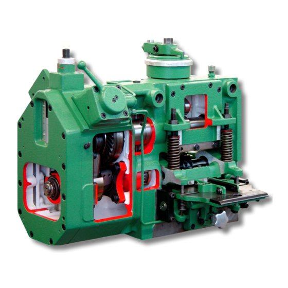
- Page 1 BBV 190 Adjustment manual...
- Page 2 BBV 190/85 BSTA 180 – 500 BBV 190/85H Replacement and Adjustment of the feed rollers and the clamping bar Preparations: 1. Remove the guard plate 12206.00.0.00. 2. Remove the cover sheet. 3. Set the feed length to maximum feed length. 4.
- Page 3 BBV 190/85 BSTA 180 – 500 BBV 190/85H Disassembly of the clamping bar and the feed rollers 1. Disassemble clamping bar 2. To access the clamping screws of the rollers M6x30 the eccentric shaft has to be turned accordingly. Installation of the lower feed roller 1.
- Page 4 BBV 190/85 BSTA 180 – 500 BBV 190/85H Installation of the upper feed roller 1. Bring the lower feed roller to a vertical position by turning the machine over at the bevel drive. 2. Install the upper feed roller at the roller shaft 12112.00.0.00 but do not tighten and position at the arrest point.
- Page 5 BBV 190/85 BSTA 180 – 500 BBV 190/85H Basic setting of the feed rollers and the clamping bar 1. Set the material thickness scale to zero. 2. Remove the plug screw M14x1,5. 3. Set feeding length to 20mm. 4. Set the spring force of the roller press springs to 10mm. 5.
- Page 6 BBV 190/85 BSTA 180 – 500 BBV 190/85H 9. Push two foils with a thickness of 0,02mm under the feed rollers on the left and the right hand side (length of foil approx. 250mm). 10. Place two foils with a thickness of 0,02mm on the left and the right hand side between the clamping bar and strip feeding table.
- Page 7 BBV 190/85 BSTA 180 – 500 BBV 190/85H 15. By turning the strip thickness adjustment counter-clockwise the feed rollers are lifted until the two foils are free. Please mark the setting on the scale. Import: Should both foils not be released at the same time, the adjustment process has to be repeated starting with item 12.
- Page 8 BBV 190/85 BSTA 180 – 500 BBV 190/85H Roller lifting adjustment 1. Set the control valve to semi-lifting position (clamping bar closed and feeder rollers open) 2. Press the piston by hand to the limit stop. 3. Open the adjusting screw until there is no pressure on the limit stop.
- Page 9 BBV 190/85 BSTA 180 – 500 BBV 190/85H 7. Should the tappet pins not be free, loosen up the pin screws until both pins are free. Restart at point 6 again. 8. Turn the first tappet pin screw 12331.00.0.00 clockwise until the tappet pin lays starts to move the dial gauge (indicator).
- Page 10 BBV 190/85 BSTA 180 – 500 BBV 190/85H...
- Page 11 BBV 190/85 BSTA 180 – 500 BBV 190/85H Pneumatic diagram MVLV x BBV 190/195 1 Inlet from the air receiver 2 Operating mode valve ( hand ) 3 Solenoid valve BBV left Y407 / BBV right Y417 4 Air cylinder upper 5 Air cylinder lower 6 Stop pin x)
Need help?
Do you have a question about the BBV 190 Series and is the answer not in the manual?
Questions and answers