Table of Contents
Advertisement
© Copyright Inspur 2016. All rights reserved.
No part of this document may be reproduced or transmitted in any form or by any means
without prior written consent of Inspur.
The information in this manual is subject to change without notice.
Inspur is the registered trademark of Inspur. All the other trademarks or registered
trademarks mentioned in this manual are the property of their respective holders.
Edition: 1
Sep 2016
Advertisement
Table of Contents
Troubleshooting

Related Manuals for Inspur SA5212M4


Summary of Contents for Inspur SA5212M4
- Page 1 Inspur. The information in this manual is subject to change without notice. Inspur is the registered trademark of Inspur. All the other trademarks or registered trademarks mentioned in this manual are the property of their respective holders.
- Page 2 4.Please use the driver shipped with the server or provided in Inspur official website, if you use non-Inspur driver, it may cause compatibility issues and affect the normal use of the product, Inspur will not assume any responsibility or liability.
-
Page 3: Table Of Contents
Table of Content 1 Safety Instructions ......................1 2 Product Specification Introduction ...................6 2.1 Introduction ........................6 2.2 Features and Specification ...................6 3 Component Identification ....................9 3.1 3.5×12 Disk Position ....................9 3.2 Hard Drive Bay LEDs ....................9 3.3 Rear Panel ........................10 3.4 System Board Components ..................11 3.5 System Board Jumper Introduction ................13 4 Operations ........................14 4.1 Power up the Server .....................14... - Page 4 6 Hardware Options Installation ..................24 6.1Processor Option ......................24 6.2 Memory Options ......................26 6.3 Hot-plug Hard Drive Option ..................27 6.4 Removing a Hot-plug Hard Drive ..................28 6.5 Redundant Hot-plug Power Supply Option ..............29 6.6 PCIE Expansion Card Replacement ................30 6.7 Air Baffle Replacement ....................30 7 Cabling ..........................31 8 BIOS Setup ........................32 8.1 System BIOS Setup Methods ..................32...
- Page 5 12.5 Disposal of Waste Equipment by Users in the European Union .........98 12.6 Korean Notice ......................99 12.7 Chinese Notice ......................99 12.8 Battery Replacement Notice ..................99 13 Electrostatic Discharge ....................101 13.1 Preventing Electrostatic Discharge ................101 13.2 Grounding Methods to Prevent Electrostatic Discharge ..........101 14 Inspur Support Guide ....................102...
-
Page 6: Safety Instructions
For your safety, please do not attempt to remove the cover of the system to remove or replace any component without assistance provided by Inspur. Only service technicians trained by Inspur are authorized to remove the cover of the host, and to remove and replace internal components. - Page 7 please do not use or attempt to operate the equipment. Contact and consult an electrician. Please do not push any objects into the openings of the system. Doing so may cause fire or electric shock. Please place the system far away from the cooling plate and heat sources, and be sure not to block the air vents.
- Page 8 Close the host cover, reconnect the system to the power socket, and then power In case of operation failure or other abnormal situations, please contact Inspur and get technical support.
- Page 9 Upon receiving the proper authorization from Inspur and dismounting the internal components, please pay attention to the following: Switch the system power supply off and disconnect the cables, including all connections of the system.
- Page 10 Safety Introduction the followings: After the rack installation is finished, please ensure that the stabilizers have been fixed to the rack and supported to ground, and the weight of the rack is firm on ground. Always load from the bottom up, and load the heaviest items first. When pulling out the components from the rack, apply slight force to keep the rack balanced.
-
Page 11: Product Specification Introduction
2 Product Specification Introduction 2.1 Introduction This type is a kind of server product developed independently. It adopts Intel Grantley-EP platform, and uses Wellsburg chip set. It supports two mainstream Intel Xeon E5-26** V4(or E5-26** V3) series processors. It supports 16 DIMM DDR4 memory, reaching up to 2400MHz. - Page 12 Product Specification Introduction Memory Memory Type DDR4 ECC RDIMM/LRDIMM memory Single Inline Memory Module Qty. Memory Volume It supports up to 1024GB (64GB for single) I/O Interface USB Interface 2 rear set USB 3.0 interfaces, and 2 built-in USB 3.0 interfaces 1 front set VGA interface Display Interface 1 rear set VGA interface...
- Page 13 External Storage Driver CD Driver External USB CD drive. Drive U Disk Optional drive U disk. Power Supply Output power of sing/Double power 550W/800W and above; 1+1 Specification redundancy; 2 power modules; it supports PMBus power supply, and implements Node Manager 3.0 function. Power Input Please refer to power input on nameplate tag of the host.
-
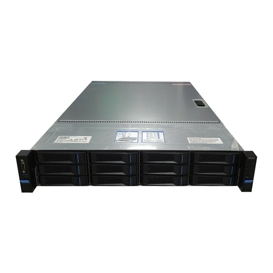
Page 14: Component Identification
Component Identification 3 Component Identification 3.1 3.5×12 Disk Position Number Module Name Front set VGA interface Front set USB 3.0 interface Securing buckle of server and cabinet Front set hard disk slot Server switch button ID light and button System fault indicator button LCD liquid crystal management module interface 3.5×12 disk position hard disk sequence diagram 3.2 Hard Drive Bay LEDs... -
Page 15: Rear Panel
3.3 Rear Panel Number Module Name Rear set 2.5 inch hard disk slot PCIE slot (half height) PCIE slot (full height) Power supply 0 Power supply 1 10 Gigabit net card interface BMC reset button ID light and button Gigabit net card interface VGA interface USB3.0 interface IPMI management interface... -
Page 16: System Board Components
Component Identification 3.4 System Board Components Number Module Name Memory slot (corresponding with CPU0) CPU0 Memory slot (corresponding with CPU1) CPU1 GPU Power supply interface System fan interfaces (8 interfaces in all) I2C interface GPIO interface IPMB interface SATA interfaces (6) - Page 17 Number Module Name CLEAR CMOS jumper TCM interface COM interface sSATA interfaces (4) Front set USB 3.0 interface Built-in USB 3.0 interface Front set VGA interface IPMI management interface / rear set USB 3.0 interface (2) PCIEx24 slots (corresponding with CPU1) Rear set VGA interface Debug light Gigabit network port...
-
Page 18: System Board Jumper Introduction
Component Identification 3.5 System Board Jumper Introduction See [2.5 Mainboard Layout] for jumper positions. Clear CMOS Jumper Introduction Jumper No. Function Description Jumper Functions Short-circuit pin1-2, to restore normal status; short- CLR_CMOS CMOS clear jumper circuit pin2-3, to clear CMOS. Note: It is required to shut down the system, as well as disconnect power supply during CMOS cleaning, and hold for 5 seconds after short-circuiting Pin2-3;... -
Page 19: Operations
4 Operations 4.1 Power up the Server Insert the power cord plug, then press the Power On button. 4.2 Power down the Server WARNING: To reduce the risk of personal injury, electric shock, or damage to the equipment, remove the power cord to remove power from the server. The front panel Power On button does not completely shut off system power. -
Page 20: Remove The Access Panel
Operations After performing the installation or maintenance procedure, slide the server back into the rack, and then press the server firmly into the rack to secure it in place. WARNING: To reduce the risk of personal injury, be careful when sliding the server into the rack. -
Page 21: Install The Access Panel
To remove the component: Power down the server if performing a non-hot-plug installation or maintenance procedure. Extend the server from the rack. Use the screwdriver to loosen the security screw on the hood latch. Lift up on the hood latch handle, and then remove the access panel. 4.5 Install the Access Panel Place the access panel on top of the server with the hood latch open. - Page 22 Operations Extend or remove the server from the rack. Remove the access panel. Remove the air baffle.
-
Page 23: Setup
Leave a minimum clearance of 121.9 cm (48 in) from the back of the rack to the back of another rack or row of racks. Inspur Servers draw in cool air through the front door and expel warm air through the rear door. Therefore, the front and rear rack doors must be adequately ventilated to allow ambient room air to enter the cabinet, and the rear door must be adequately ventilated to allow the warm air to escape from the cabinet. - Page 24 Setup CAUTION: If a third-party rack is used, observe the following additional requirements to ensure adequate airflow and to prevent damage to the equipment: • Front and rear doors—If the 42U rack includes closing front and rear doors, you must allow 5,350 sq cm (830 sq in) of holes evenly distributed from top to bottom to permit adequate airflow (equivalent to the required 64 percent open area for ventilation).
- Page 25 WARNING: To reduce the risk of personal injury, fire, or damage to the equipment, do not overload the AC supply branch circuit that provides power to the rack. Consult the electrical authority having jurisdiction over wiring and installation requirements of your facility.
-
Page 26: Rack Warnings
Because of the high ground-leakage currents associated with multiple servers connected to the same power source, Inspur recommends the use of a PDU that is either permanently wired to the building’s branch circuit or includes a nondetachable cord that is wired to an industrial-style plug. -
Page 27: Installing Hardware Options
The contents of the server shipping carton include: ● Server ● Power cord ● Power cord clasp ● Hardware documentation, Documentation CD, and software products ● Rack-mounting hardware In addition to the supplied items, you may need: ● Operating system or application software ●... -
Page 28: Installing The Operating System
5.6 Installing the Operating System To operate properly, the server must have a supported operating system installed. For the latest information on supported operating systems, refer to the Inspur website (http://www.inspur.com/eportal/ui?pageId=444443). Methods to install an operating system on the server include: ●... -
Page 29: Hardware Options Installation
6 Hardware Options Installation Introduction If more than one option is being installed, read the installation instructions for all the hardware options and identify similar steps to streamline the installation process. WARNING: To reduce the risk of personal injury from hot surfaces, allow the drives and the internal system components to cool before touching them. - Page 30 Hardware Options Installation Step 1: Open the two locking levers and the CPU fixing plate. Step 2: Install CPU into the CPU socket, and then remove the protective cover. Step 3: Clamp CPU with CPU fixing plate, and then close the two locking levers firmly.
-
Page 31: Memory Options
Note: ● It is required to coat thermal grease evenly onto the contact position between CPU heatsink and CPU. ●The direction of CPU heatsink fins should be identical with the system inlet/outlet direction. ● During fixing CPU heatsink, it is required to fasten bolts according to diagonal sequence accordingly. -
Page 32: Hot-Plug Hard Drive Option
Hardware Options Installation ● Memory installation principle: Only memory of the same type could be used in the same machine. Detailed memory installation and combination principles are as follows: The white slot shall take the priority, while CPU1 memory shall be symmetrically installed with CPU0. -
Page 33: Removing A Hot-Plug Hard Drive
Prepare and install the hard drive. Determine the status of the hard drive from the hot-plug SAS hard drive LED combinations. 6.4 Removing a Hot-plug Hard Drive CAUTION: For proper cooling do not operate the server without the access panel, baffles, expansion slot covers, or blanks installed. -
Page 34: Redundant Hot-Plug Power Supply Option
Hardware Options Installation 6.5 Redundant Hot-plug Power Supply Option Step 1: Pull power catch in the direction of the arrow. Step 2: Remove the power horizontally with even force. Figure 3: Install power module. Push the new power module into the sliding channel, until a “click” sound is heard, power spring leaf is caught into the buckle automatically, and power module could not move any more. -
Page 35: Pcie Expansion Card Replacement
6.6 PCIE Expansion Card Replacement Step 1: Remove the blocking piece on riser card bracket. Step 2: Install a matching blocking piece onto expansion card, and insert the expansion card into the slot corresponding to riser card. Step 3: Install the riser card bracket back to the server. 6.7 Air Baffle Replacement Step 1: Open the top cover of the chassis. -
Page 36: Cabling
Cabling 7 Cabling The SAS cable (blue) is used to connect the front backplane and SAS/RAID card; The power cable (red) is used to connect the front backplane and motherboard. CAUTION: Please route the cables according to your purchased machine. -
Page 37: Bios Setup
8.1 System BIOS Setup Methods Power on the server. The system will then start to boot. When the following content appears below Inspur logo on the screen: ● Press <DEL> to SETUP or <TAB> to POST or <F12> to PXE Boot. -
Page 38: Bios Configuration
BIOS Setup Note: Options in grey are not available. Options with symbol “” have a sub-menu. Control key instruction table Press Key Function <Esc> Exit or return from sub-menu to main menu < ← > or < → > Select a menu <... - Page 39 Main Menu Interface Instruction Table Interface Parameters Function Description BIOS Information Displays current BIOS information. Processor Information Displays CPU information. Memory Information Displays memory volume and current speed. System Date(Day mm/dd/yyyy) Displays system time. System Time (hh/mm/ss) Access Level Current access level 8.2.2 Advanced Menu Advanced Menu Interface Instruction Table Interface Parameters...
- Page 40 BIOS Setup Trusted Computing Menu Interface Instruction Table Interface Parameters Function Description Security Device Support BIOS’s security device support settings Current Status Information Status information of the current security device 8.2.2.2 ACPI Settings Advanced Menu Interface Instruction Table Interface Parameters Function Description Enable ACPI Auto Configuration To allow ACPI’s automatic configuration.
- Page 41 AST2400 Super IO Configuration Menu Interface Instruction Table Interface Parameters Function Description Super IO Chip The current I/0 chip Serial Port 1 Configuration Serial port 1 configuration 8.2.2.4 Serial Port Console Redirection Serial Port Console Redirection Menu Interface Instruction Table Interface Parameters Function Description Console Redirection...
- Page 42 BIOS Setup Console Redirection Settings Menu Interface Introduction Interface Parameters Function Description Terminal Type Terminal type settings Bits per second Baud rate settings Data Bits Data bits settings Parity Parity check settings Stop Bits Stop bits settings Flow Control Flow control settings VT-UTF8 Combo Key Support VT-UTF8 Combo key support settings Recorder Mode...
- Page 43 8.2.2.5 PCI Subsystem Settings PCI Subsystem Settings Menu Interface Instruction Table Interface Parameters Function Description PCI Latency Timer PCI delay timer settings PCI-X Latency Timer PCI-X delay timer settings VGA Palette Snoop VGA color correction settings 64bit equipment’s decoding settings on address Above 4G Decoding space larger than 4G.
- Page 44 BIOS Setup CSM Configuration Menu Interface Instruction Table Interface Parameters Function Description CSM Support CSM support settings GateA20 Active A20 address line’s control mode settings Option Rom Message Option Rom display mode settings Boot option filter Boot option filter settings Option ROM execution Option Rom execution method Network...
- Page 45 8.2.2.8 Onboard LAN Configuration Onboard LAN Configuration Menu Interface Instruction Table Interface Parameters Function Description Onbaord I350 NIC1 Control Onboard network card NIC1 switching settings Onboard PXE Lan ROM Settings Onboard Lan PXE option switch settings 8.2.3 Chipset Menu...
- Page 46 BIOS Setup Chipset Menu Interface Instruction Table Interface Parameters Function Description Processor Configuration Processor configuration Advanced Power Management Configuration Advanced power management configuration QPI Configuration QPI configuration Memory Configuration Memory configuration IIO Configuration IIO configuration PCH Configuration PCH configuration Server ME Configuration Server ME configuration Runtime Error Logging Runtime error log configuration...
- Page 47 Intel hardware-assisted virtualization technology settings Safe mode expansion settings Hardware Prefetcher Hardware prefetch settings Adjacent Cache Prefetch Adjacent high speed cache prefetch settings DCU Streamer Prefetcher DCU Streamer prefetch settings DCU IP Prefectcher DCU IP prefetch settings Direct Cache Access (DCA) Direct high speed cache access settings AES-NI Intel AES-NI advanced encryption standard settings...
- Page 48 BIOS Setup CPU P State Control CPU P State Control Menu Interface Instruction Table Interface Parameters Function Description EIST(P-states) EIST switching settings Turbo Mode Turbo mode switching settings CPU C State Control...
- Page 49 CPU C State Control Menu Interface Instruction Table Interface Parameters Function Description Package C State limit C state limit settings CPU C3 report C3 switching settings CPU C6 report C6 switching settings Enhanced Halt State (C1E) C1E switching settings Energy Performance Tuning Energy Performance Tunning Menu Interface Instruction Table Interface Parameters Function Description...
- Page 50 BIOS Setup 8.2.3.3 QPI Configuration QPI Configuration Menu Interface Instruction Table Interface Parameters Function Description QPI Satus QPI status display sub-menu Degrade Precedence To degrade to priority settings. Link Speed Mode Link speed mode settings Link Frequency Select Link frequency selection settings Link power saving mode settings, which is made when Link L0p Enable bandwidth is half of the peak bandwidth..
- Page 51 8.2.3.4 Memory Configuration Memory Configuration Menu Interface Instruction Table Interface Parameters Function Description Enforce POR To execute POR settings Memory Frequency Memory frequency settings ECC Support ECC support settings Rank Multiplication Rank multiplication settings LRDIMM Module Delay LRDIMM module delay settings Data Scrambling Data scrambling settings Refresh Options...
- Page 52 BIOS Setup Memory RAS Configuration Memory RAS Configuration Menu Interface Instruction Table Interface Parameters Function Description As for memory mode configuration, there’re 3 options of Memory Mode [Independent], [Mirroring] and [Lock Step]. Lockstep X4 DIMMs X4 DIMMs’ Lockstep switching settings Memory Rank Sparing Memory Rank hot sparing settings Correctable Error Threshold...
- Page 53 8.2.3.5 IIO Configuration IIO Configuration Menu Interface Instruction Table Interface Parameters Function Description IIO0 configuration sub-menu, used to set link speed of PCIE IIO0 Configuration device of CPU0. IIO1 configuration sub-menu, used to set link speed of PCIE IIO1 Configuration device of CPU1.
- Page 54 BIOS Setup PCH Configuration Menu Interface Instruction Table Interface Parameters Function Description Chassis Intrusion Chassis intrusion switching settings Restore AC Power Loss AC power-on power status settings PCH sSATA Configuration PCH sSATA configuration sub-menu PCH SATA Configuration PCH SATA configuration sub-menu USB Configuration USB configuration sub-menu PCH SATA Configuration...
- Page 55 Press<CTRL-I> to enter Configuration Utility… Meanwhile, press [Ctrl] and [I] synchronously to enter SATA RAID configuration interface, and one example is as shown in the following figure. After entering SATA RAID configuration interface, menu list information, information of hard disk connecting to SATA controller (hard disk ID number, hard disk type, hard disk capacity as well as whether hard disk is a volume member etc.), existed RAID volume information (including volume ID number, name, RAID level, capacity, status, whether information bootable) will all display.
- Page 56 BIOS Setup a)Create RAID Volume Menu After entering SATA RAID configuration interface, you could use up and down arrows to select this menu, then press [Enter] to create an RAID volume menu, or directly enter the number before the menu to create an RAID volume menu, for other menu operations are similar, so it will not be repeated here.
- Page 57 Here we enter “Y” to create an RAID volume, after creation completed, return to SATA Host RAID configuration main interface, and the created RAID volume will display in RAID volume. Delete RAID Volume Menu After entering Delete RAID Volume menu, system prompts: “Deleting a volume will reset the disks to non-RAID.
- Page 58 BIOS Setup you sure you want to reset RAID data on selected disks? (Y/N)” again, enter “Y” or “N” according to prompt. It is to be noted that, during resetting hard disk, data on this disk will all be lost, meanwhile, this disk will not belong to RAID volume any more. Exit Menu System prompts: "...
- Page 59 ME Firmware Status #1 ME FW status value #1 ME Firmware Status #2 ME FW status value #2 Current State Current state Error code ME FW error code 8.2.3.8 Common Configuration Common Configuration Menu Interface Instruction Table Interface Parameters Function Description MMCFG Base MMCFG base address settings Isoc Mode...
- Page 60 BIOS Setup 8.2.4 Server Mgmt Server Mgmt Menu Interface Instruction Table Interface Parameters Function Description BMC Firmware Version BMC firmware version FRB-2 TImer FRB-2 clock settings FRB-2 Timer timeout FRB-2 clock expiration time settings FRB-2 Timer policy Policy settings after FRB-2 clock expiration OS Watchdog Timer System watchdog clock settings OS Wtd Timer timeout...
- Page 61 8.2.4.1 System Event Log System Event log Menu Interface Instruction Table Interface Parameters Function Description SEL Components System event log switching settings during startup Erase SEL System event log erasing settings When SEL is Full Operation settings after system event log is full. Log EFI Staus Codes Logging EFI status codes settings 8.2.4.2 View FRU Information...
- Page 62 BIOS Setup FRU information. 8.2.4.3 BMC network configuration BMC network configuration Menu Interface Instruction Table Interface Parameters Function Description Configuration BMC Network Status Parameter: It could set Configuration Address Source static IPs, and obtain IPs dynamically, while [Unspecified] will not modify BMC network parameters. Current Configuration Address Current configuration address status Station IP adderess...
- Page 63 BIOS could carry out Dynamic and Static network settings on BMC Dedicated management port and sharelink management port, taking Dedicated management port as an example, to set a BMC Static IP as follows: Set the Get BMC Dedicated Parameters option to【Manual】 Set the Configuration Address source option to【Static】...
- Page 64 BIOS Setup 8.2.4.4 BMC User Settings BMC User Settings Menu Interface Instruction Table Interface Parameters Function Description Add User The sub-menu for adding users. Delete User The sub-menu for deleting users. Change User Settings The sub-menu for modify user settings. Add User operation...
- Page 65 Select the User Name option, and press Enter to pop up the User Name box, enter the user name to set manually, after configuration is completed, press Enter to confirm. Select the User Password option, and press Enter to pop up the User Password box, enter the user password to set manually, after configuration is completed, press Enter to confirm.
- Page 66 BIOS Setup Delete User operation Select the User Name option, and press Enter to pop up the User Name box, manually enter the user name to delete, after configuration is completed, press Enter to confirm. Select the User Password option, and press Enter to pop up the User Password box, manually enter the user password to delete, after that, press Enter to confirm, and the BMC USER SETTINGS INFO prompt will pop up, indicating user password deletion is done or not.
- Page 67 Select the User Name option, and press Enter to pop up the User Name box, manually enter the user name to modify, after configuration is completed, press Enter to confirm. Select the User Password option, and press Enter to pop up the User Password box, manually enter the user password, and press Enter to confirm.
- Page 68 BIOS Setup System Temperature Information System Fan Speed...
- Page 69 System Voltage Information 8.2.5 Security Menu Security Menu Interface Instruction Table Interface Parameters Function Description Administrator Password Create a password for administrator. User Password Create a password for normal user.
- Page 70 BIOS Setup 8.2.6 Boot Menu Boot configuration Menu Interface Instruction Table Interface Parameters Function Description Bootup NumLock State Numlock keys status settings after bootup. Boot Options Retry The booting device polling settings To boot quietly, set this option to Enabled, and boot logo displays as that set by manufacturer, disabled, boot logo Quiet Boot displays as AMI’s default logo.
- Page 71 Taking Boot option #1 as an example, you could set the first boot device for the system: Move the cursor to Boot option #1, and press Enter, to pop up the boot option for selection: i.e. IBA GE slot 0400 v1543, UEFI: Built-in EFI Shell, UEFI:USB2.O DISK 1100, USB2.O DISK 1100 etc., select one via up and down keys, i.e.
-
Page 72: Firmware Update
BIOS Setup Save & Exit Menu Menu Interface Instruction Table Interface Parameters Function Description Save Changes and Exit To Save and exit Discard Changes and Exit To abandon changes and exit. Save Changes and Reset To save changes and reboot Discard Changes and Reset To abandon changes and reboot Save Changes... - Page 73 /p -- Program Main BIOS /n -- Program NVRAM /x -- Don’t Check ROM ID /me -- Program ME Entire Firmware Block Use afudos tool to update BIOS in Linux OS There’re 32bit and 64bit Linux OS afulnx tools, taking Linux 64bit OS as an example, use afulnx_64 tool, to enter the directory containing afulnx_64 tool, meanwhile, put bin files of corresponding BIOS into this folder, and enter command: /afulnx_64 BIOS.BIN /P /B /N /X /R, while an example is as shown in the following figure:...
- Page 74 BIOS Setup Run AUWINGUI.EXE tool, as shown in the following figure: Click the Open button, after selecting the BIOS.bin file to update, system enters Setup interface automatically. Select Program all Blocks and Do Not Check ROM ID options on Setup interface, click flash button, system enters Progress interface automatically, and executes BIOS update accordingly according to colors shown on the right, thus BIOS update is done as shown in the following figure:...
-
Page 76: Bmc Settings
BMC Settings 9 BMC Settings 9.1 Introduction This chapter introduces specifications and main functions to be abided by management software. The distributor server management software is a control unit realizing server management, which is compatible with management standard of the server industry IPMI2.0 specification. -
Page 77: Functional Modules
● Supports WEB interface management Provides a friendly and visual interface management, and you could complete tasks of configuration and query via a click on the interface quickly. ● Supports account centralized management Supports to store accounts in Active Directory server, and direct certification to server, so as to realize management system login with domain accounts. -
Page 78: Web Interface Introduction
BMC Settings 9.2.4 Remote Control Module Introduction Remote control module includes: ● KVM Over IP: It means a management method that user carries out monitoring and control on remote devices via using local video, keyboard and mouse at client, to operate remote devices in a real-time way. - Page 79 ipaddress is the IP address of management port, for specific determining method on IP address, please refer to the annex to determine IP address of management network port) Step 3 The login interface pops up, as shown in the following figure, in this interface: Enter user name and password.
- Page 80 BMC Settings and English. Click the Help button to query help information on corresponding page. ◎ Click the Logout button, to return to login page. ◎ ● There’s a navigation tree on the left, via nodes on the tree, you could select different functional interfaces.
-
Page 81: Remote Control
● FRU information: Displays FRU information; 9.4 Remote Control Select “Remote Control” on navigation tree, to open the remote control interface,... - Page 82 BMC Settings which contains six interfaces of “Console Redirection (KVM)”, server switch-on/off control, server orientation, remote session configuration, virtual media configuration and mouse mode configuration, as shown in the following figure. ● Console redirection (KVM): To pop up the KVM console window. ●...
-
Page 83: Power Supply And Heat Radiation
9.5 Power Supply and Heat Radiation Select “Power Supply and Heat Radiation” on navigation tree, to open the power supply and heat radiation page, which contains three pages of power supply monitoring, power supply management, fan rotation rate control, as shown in the following figure. -
Page 84: Bmc Configuration
BMC Settings 9.6 BMC Configuration Select “BMC Configuration” on navigation tree, to open the BMC configuration page, which contains 10 pages of “BMC Network”, “Service Configuration”, “NTP Configuration”, “SMTP Configuration”, “Alarming Management”, “Active Directory Configuration”, “LDAP/E-Directory”, “User Configuration”, “IP Access Control”, “NCSI Network Card Selection”, as shown in the following figure. - Page 85 directory. ● LDAP/E-Directory: Carries out related configuration on BMC’s LDAP. ● User configuration: Carries out management on BMC users, including add user, delete user and change password. ● IP access control: Configures IP address fields accessible to BMC. ● NCSI network card selection: Includes NCSI network card switching, and NCSI work mode switching functions.
- Page 86 BMC Settings...
-
Page 87: Logs
9.7 Logs Select “Logs” on navigation tree, open pages related to logs, including four pages of “System Event Logs”, “BMC System Design Logs”, “Black Box Logs”, “Event Logs Settings” and “BMC System Audit Logs Settings”. ● System event logs: Displays various event logs generated by server. ●... -
Page 88: Fault Diagnosis
BMC Settings 9.8 Fault Diagnosis Select “Fault Diagnosis” on navigation tree, to open fault diagnosis page, which contains three pages of “Task Restart”, “Last Crash Screen” and “System Power On Self test codes”. As shown in the following figure. ● Task restart: Contains restart two functions of restarting BMC and restarting KVM service;... -
Page 89: System Maintenance
9.9 System Maintenance Select “System Maintenance” on navigation tree, to open system maintenance page, and system maintenance page includes three pages of “BMC Firmware Update”, “BIOS Firmware Update” and “Restore Factory Settings”, as shown in the following figure. ● BMC firmware update: Carries out update on BMC FW via BMC Web interface; ●... -
Page 90: Command Line Function Introduction
BMC Settings 9.10 Command Line Function Introduction About this chapter It introduces Web interface of management system as well as operation steps to login Web interface. ● Login command line Introduces methods of login command line. ● Command line function introduction Introduces command line functions. - Page 91 9.10.2 Command Line Function Introduction 9.10.2.1 Network Information Acquisition and Configuration: You could acquire and configure BMC’s network information via ipconfig instruction: 9.10.2.2 Sensor Information Acquisition: Via sensor instruction, you could acquire all sensor information lists:...
- Page 92 BMC Settings 9.10.2.3 FRU Information Acquisition and Configuration: Via FRU instruction, you could acquire FRU configuration information: 9.10.2.4 Chassis Status Acquisition and Control: Via chassis instruction, you could acquire and control system power status. Acquiring system power status: 9.10.2.5 User Acquisition, Adding and Deleting: Via user instruction, you could acquire the user list, to add or delete users.
- Page 93 Acquiring user list: 9.10.2.6 BMC Version Acquisition and BMC Restart Via mc instruction, you could acquire BMC version information, and restart BMC. Acquiring BMC version information: 9.10.2.7 Fan Work Mode Configuration and Fan Rotation Rate Acquisition: Via fan instruction, you could either set fan work mode, or acquire fan rotation rate.
- Page 94 BMC Settings Fan rotation rate acquisition: 9.10.2.8 Power Module Information Acquisition and Configuration: Via Psu instruction, you could either acquire power module information, or set power module as main output. Power module information acquisition: 9.10.2.9 Change Root Password: Via password instruction, you could change root user’s password:...
-
Page 95: Time Zone Table
9.11 Time Zone Table Time Zone Countries and Regions GMT-12:00 West Date Line GMT-11:00 Appiah, Niue, Pago Pago, Midway GMT-10:00 Fakaofo, Rarotonga, the island of Tahiti, Johnston, Hawaii GMT-09:30 Marquesas GMT-09:00 Alaska, Gambier Islands GMT-08:00 Pacific Time (USA and Canada), Pitcairn, Whitehorse, Tijuana, Vancouver Mountain Time (USA and Canada), Edmonton, Hermosillo, the Tao gave birth to GMT-07:00 Crick, Chihuahua, Yellowknife, Arizona, Mazatlan... - Page 96 Common Faults, Diagnosis and Troubleshooting GMT+04:30 Kabul Aktau Aktobe, Ashkhabad, Karachi, Dushanbe, Kell islands, Maldives, Kelang, GMT+05:00 Yekaterinburg, Tashkent GMT+05:30 Colombo, India GMT+06:00 Ala Mutu, Bishkek, Chagos, Dhaka, Mo Sen, Omsk, Novosibirsk, Thimphu, Vostok GMT+06:30 The Coco Islands, Yangon Davies, Hanoi, Phnom Penh, Khovd, Bangkok, Lasinuoyaersike, Christmas Island, GMT+07:00 Vientiane, Jakarta Macao, Kuala Lumpur, Manila, Ilkuts J, Casey, Macassar, Taipei, Brunei, Ulan Bator,...
-
Page 97: Common Faults, Diagnosis And Troubleshooting
10 Common Faults, Diagnosis and Troubleshooting This chapter introduces the common server faults, as well as corresponding diagnosis and troubleshooting suggestions. 10.1 Common Faults No power after startup ● After the machine is connected with power cable, no power is provided for the machine while pressing the On/Off button. -
Page 98: Diagnosis And Troubleshooting Instructions
If there is a machine and a power module of the same type, you could change the power module to test whether there is a power module fault. If the instructions above do not resolve the problem, please contact Inspur customer service. - Page 99 Operation steps: Please check whether all power module indicators are steadily green, if so, you can login BMC web interface to collect logs, and contact Inspur customer service. Memory capacity incomplete Description: Memory capacity viewed via the operating system does not correspond with physical memory capacity.
- Page 100 Check whether the USB device is normal when connecting to other hosts. If the USB device is normal when connecting to other hosts, the server may be abnormal: please call Inspur technical hotline for support. If the USB device turns out to be abnormal when connecting to other hosts, please...
-
Page 101: Battery Replacement
Remove the full-length expansion board retainer if any full-length expansion boards are installed. Remove the PCI riser cage. Remove the air baffle. Remove the battery. To replace the component, reverse the removal procedure. For more information about battery replacement or proper disposal, contact Inspur Customer Service. -
Page 102: Regulatory Compliance Notices
Regulatory Compliance Notices 12 Regulatory Compliance Notices 12.1 Regulatory Compliance Identification Numbers For the purpose of regulatory compliance certifications and identification, this product has been assigned a unique regulatory model number. The regulatory model number can be found on the product nameplate label, along with all required approval markings and information. -
Page 103: Cables
Compliance with these directives implies conformity to applicable harmonized European standards (European Norms) that are listed in the EU Declaration of Conformity issued by INSPUR for this product or product family and available (in English only) within the product documentation. -
Page 104: Korean Notice
Regulatory Compliance Notices point for the recycling of waste electrical and electronic equipment. The separate collection and recycling of your waste equipment at the time of disposal will help to conserve natural resources and ensure that it is recycled in a manner that protects human health and the environment. - Page 105 Batteries, battery packs, and accumulators should not be disposed of together with the general household waste. To forward them to recycling or proper disposal, use the public collection system or return them to Inspur, an authorized Inspur Partner, or their agents.
-
Page 106: Electrostatic Discharge
Use a portable field service kit with a folding static-dissipating work mat. If you do not have any of the suggested equipment for proper grounding, have an authorized reseller install the part. For more information on static electricity or assistance with product installation, contact Inspur Customer Service. -
Page 107: Inspur Support Guide
14 Inspur Support Guide ● Inspur Global Service Support Global Technical Service Hotline: 1-844-860-0011 (Toll Free) 1-646-517-4966 (Direct Phone) Global Technical Service Email: serversupport@inspur.com ● Information customer needs to provide when requesting for support: Contact name Phone number E-mail address...
Need help?
Do you have a question about the SA5212M4 and is the answer not in the manual?
Questions and answers