
Summary of Contents for Textron GSE 660-28
- Page 1 IntroductionIntroduction MODEL 660-28 MOBILE BELT LOADER OPERATION MANUAL CD397-Oper June 2019 (Rev C)
- Page 2 Mobile Belt Loader Model 660-28 Introduction Operation Manual CALIFORNIA PROPOSITION 65 WARNING: The engine exhaust from this product contains chemicals known to the State of California to cause cancer, birth defects or other reproductive harm. WARNING WARNING WARNING WARNING Operating, servicing and maintaining a...
- Page 3 Textron GSE. Any attempt to alter the contents of this manual in any way by anyone other than an authorized agent of Textron GSE shall be construed as copyright infringement and punishment will be pursued under all applicable laws.
- Page 4 Mobile Belt Loader Model 660-28 Introduction Operation Manual RECORD OF REVISIONS Property of: _______________________________________________________________ Company: _______________________________________________________________ Address: _______________________________________________________________ City: ___________________________ State/Province: _____________ Country ___________________________ Zip/Postal Code: _____________ Revision Date: June 2019 Check each revision received, and insert the revised and supplementary pages in your manual.Textron GSE assumes no liability for personal injury or equipment failure due to any operation performed without heed to manual revisions.
- Page 5 Introduction Mobile Belt Loader Model 660-28 Operation Manual LIST OF EFFECTIVE PAGES Table Introduction-1-2: List of Revisions Page Revision Date Page Revision Date August 2018 Front Cover June Safety-2-1 to Safety-2-17 2019 Operation-2-10 to Operation-2-11 CD397-Oper Introduction - 1 - v June 2019 (Rev C)
- Page 6 Mobile Belt Loader Model 660-28 Introduction Operation Manual THIS PAGE INTENTIONALLY BLANK Introduction - 1 - vi CD397-Oper June 2019 (Rev C)
-
Page 7: Table Of Contents
Introduction Mobile Belt Loader Model 660-28 Operation Manual MANUAL TABLE OF CONTENTS Introduction - - - - - - - - - - - - - - - - - - - - - - - - - - - - - - - - - - - -Introduction-1-i... - Page 8 Mobile Belt Loader Model 660-28 Introduction Operation Manual 2.1.1.1: Engine Danger Areas - - - - - - - - - - - - - - - - - - - - - - - - - - - - - - - - Safety-2-1 2.1.1.2: Engine Danger Area Diagrams - - - - - - - - - - - - - - - - - - - - - - - - - Safety-2-1...
- Page 9 Introduction Mobile Belt Loader Model 660-28 Operation Manual 1.3.9: Fuel System - - - - - - - - - - - - - - - - - - - - - - - - - - - - - - - - - - - - - - - Operation-1-4 1.3.10: Electrical System - - - - - - - - - - - - - - - - - - - - - - - - - - - - - - - - - - - Operation-1-4...
- Page 10 Mobile Belt Loader Model 660-28 Introduction Operation Manual 2.3.6.1: Conveyor Safety Props - - - - - - - - - - - - - - - - - - - - - - - - - - - - Operation-2-12 2.3.7: Park Brake Operation- - - - - - - - - - - - - - - - - - - - - - - - - - - - - - - - Operation-2-13...
- Page 11 Introduction Mobile Belt Loader Model 660-28 Operation Manual 5.1.1.2: Transmission - - - - - - - - - - - - - - - - - - - - - - - - - - - - - - - - - - - - Operation-5-1 5.1.1.3: Drive Axle - - - - - - - - - - - - - - - - - - - - - - - - - - - - - - - - - - - - - - Operation-5-1...
- Page 12 Mobile Belt Loader Model 660-28 Introduction Operation Manual THIS PAGE INTENTIONALLY BLANK Introduction - 1 - xii CD397-Oper June 2019 (Rev C)
-
Page 13: List Of Figures
Figure Operation-1-6: Seat and Seat Switch ............Operation-1-9 Figure Operation-1-7: Conveyor Proximity Switch..........Operation-1-9 Figure Operation-2-1: Operator’s Compartment ............Operation-2-2 Figure Operation-2-2: 660-28 Instrument Panel - Ford 2.5L........Operation-2-4 Figure Operation-2-3: Cylinder Controls ..............Operation-2-6 Figure Operation-2-4: Belt Drive Controls..............Operation-2-6 Figure Operation-3-1: Front Up, Rear Down............Operation-3-2 Figure Operation-3-2: Front Up, Rear Up ..............Operation-3-2... - Page 14 Mobile Belt Loader Model 660-28 Introduction Operation Manual Figure Operation-4-13: Threading Conveyor Lifting Strap........Operation-4-8 Figure Operation-4-14: Conveyor Lift Support............Operation-4-9 Figure Operation-4-15: Removing “Carrier” Belt Loader........Operation-4-9 Introduction- 1 - xiv CD397-Oper June 2019 (Rev C)
- Page 15 Introduction Mobile Belt Loader Model 660-28 Operation Manual Notes: CD397-Oper Introduction - 1 - xv June 2019 (Rev C)
- Page 16 Mobile Belt Loader Model 660-28 Introduction Operation Manual THIS PAGE INTENTIONALLY BLANK Introduction - 1 - xvi CD397-Oper June 2019 (Rev C)
-
Page 17: List Of Tables
Introduction Mobile Belt Loader Model 660-28 Operation Manual LIST OF TABLES Table Introduction-1-1: Revisions ..............Introduction-1-iv Table Introduction-1-2: List of Revisions............Introduction-1-v Table Introduction-1-3: Service Recalls/Notification ........Introduction-1-xxii Table Safety-1-1: Standard Safety Features/Equipment ........... Safety-1-1 Table Safety-1-2: Optional Safety Items ..............Safety-1-3 Table Safety-1-3: Operator Safety Responsibilities ........... - Page 18 Mobile Belt Loader Model 660-28 Introduction Operation Manual THIS PAGE INTENTIONALLY BLANK Introduction - 1 - xvi CD397-Oper June 2019 (Rev C)
-
Page 19: Unit Identification
The information and instructions in this manual are intended to acquaint the operator with the important operating features of the Tug Mobile Belt Loader 660-28. The various controls, gauge, switches, and operating features are explained and illustrated throughout this manual. Personnel responsible for the operation of the vehicle should read this manual carefully. -
Page 20: Model Number Coding
Mobile Belt Loader Model 660-28 Introduction Operation Manual MODEL NUMBER CODING Units are numbered according to the diagram in Figure Introduction-1-2 660-28 Model Number Coding. Model Number Coding Conveyor Engine Engine Engine Variations Conveyor Variations 660 = 34 in Wide x 24 ft Long 28 = Ford MSG-425 (2.5 L) 4 Cylinder Gasoline/LP... -
Page 21: Technical Assistance
Introduction Mobile Belt Loader Model 660-28 Operation Manual TECHNICAL ASSISTANCE Direct any questions concerning the operation of the Mobile Belt Loader Model 660-28 to: Textron Ground Support Equipment 1995 Duncan Dr. Kennesaw, GA 30144 U.S. Phone: (770)-422-7230 Sweden: +46 (410) 140 50 Cheltenham: +44(0)1242 531201 Email: GSESales@textron.com... -
Page 22: Technical Service Bulletins
Mobile Belt Loader Model 660-28 Introduction Operation Manual TECHNICAL SERVICE BULLETINS There are no applicable Technical Service Bulletins to include for the Model 660-28 Mobile Belt Loader. Introduction - 1 - xx CD397-Oper August 2018 (Rev B) -
Page 23: Warranty Information
- all aspects of the products themselves and the service that backs them up. This manual is directed to Textron GSE’s distributors and customers of Textron GSE. It should be used to implement the Warranty Program at every level. -
Page 24: Warranty
WARRANTY A warranty is a specific document that guarantees the quality of goods to a purchaser within a specified length of time and according to usage limitations. The Textron GSE warranty statement defines the conditions of the warranty. A warranty: •... - Page 25 Any repair made to a product that has been misused or mistreated, or upon which a conversion, modification, or installation of a non-Tug part has been made affecting the performance, reliability, or stability of a part. Any failure to a Textron GSE-supplied part resulting from such action is not covered by NOTE: the warranty.
- Page 26 Return Parts: Not all failed parts need to be returned to Textron GSE. If parts are to be returned, an RGA tag will be sent with the replacement warranty parts. The tag must be filled out completely and attached to the return part(s).
- Page 27 All the expenses related to a warranty claim will be invoiced to the buyer until Textron GSE has evaluated the claim. Whatever the circumstances, the buyer should not refuse or delay the payment. If the evaluation determines Textron GSE’s full responsibility, a credit will be issued in favor of the buyer.
-
Page 28: How To Use This Manual
Introduction Operation Manual HOW TO USE THIS MANUAL Textron GSE recommends that the vehicle operator thoroughly study the contents of this manual before attempting to operate the vehicle. This manual contains the Introduction, Safety and Operation chapters. Refer to the Table of Contents at the front of this manual for details regarding chapter content. -
Page 29: Figure Introduction-1-4: Table And Figure Numbering System
Introduction Mobile Belt Loader Model 660-28 Operation Manual Tables and figures are numbered independently and consecutively. Similarly to page number formatting, tables and figures are given a five part caption. • The first variable appears as “Figure” or “Table” to identify the type of graphic. - Page 30 Mobile Belt Loader Model 660-28 Introduction Operation Manual THIS PAGE INTENTIONALLY BLANK Introduction - 1 - xxviii CD397-Oper August 2018 (Rev B)
-
Page 31: Safety
Operation Manual Safety Section 1: General Safety Guidelines Operator and mechanic safety is important at Textron GSE. Safety warnings, cautions, and notes provided throughout this manual. It is important that operators and mechanics become familiar with all safety requirements. To reinforce this action, this section of the manual has been devoted to safety. It is strongly recommended that this chapter be reproduced and bound in the operator’s book, along with your station safety rules. - Page 32 Mobile Belt Loader Model 660-28 Safety Operation Manual Section 1 Table Safety-1-1: Standard Safety Features/Equipment (Continued) Features/Equipment Hydraulic steering Pilot pressure operated cylinder holding valves Pilot pressure operated reverse belt holding valve All hydraulic hoses rated at 3250 psi (22.41 mPa or 221.15 atm). Hand and/or Guide Rails on either side of the conveyor...
-
Page 33: 2: Optional Safety Features/Equipment
Safety Mobile Belt Loader Model 660-28 Section 1 Operation Manual 1.1.2 Optional Safety Features/Equipment The following table contains a list of optional safety features/equipment: Table Safety-1-2: Optional Safety Items Items Backup alarm LED Amber Beacon (Flashing, Rotating, or Strobe) Work lights Gap filler strip between conveyor belt an d front rubber bumper... -
Page 34: 1.2 Safety Features
Mobile Belt Loader Model 660-28 Safety Operation Manual Section 1 1.2 Safety Features 1.2.1 Emergency Stop Switch The Emergency Stop Switch is a push-button switch located on the dash and all control points on the conveyor belt assembly and the belt loader. The Emergency Stop Switch stops the conveyor and engine immediately in an emergency situation. -
Page 35: Table Safety-1-3: Operator Safety Responsibilities
Safety Mobile Belt Loader Model 660-28 Section 1 Operation Manual Table Safety-1-3: Operator Safety Responsibilities Operator Responsibilities Use proper eye, foot and hearing protection Follow training provided by your company Check before operating the unit: • Lights • E-stops • Hood Latches • Brakes •... -
Page 36: 2: Mechanic Safety Responsibility
Mobile Belt Loader Model 660-28 Safety Operation Manual Section 1 Table Safety-1-3: Operator Safety Responsibilities (Continued) Operator Responsibilities Do not ride on the belt, conveyor, or fenders. In even of a malfunction, stop operations and move the loader to a safe area, if possible, then notify a supervisor Do not stand on the belt when it is moving. -
Page 37: 1: Lp And Cng Safety Information
Safety Mobile Belt Loader Model 660-28 Section 1 Operation Manual Table Safety-1-4: Mechanic Safety Responsibilities (Continued) Mechanic Safety Responsibilities Keep hands, gloves, and clothing clear of cooling fan. Disconnect the battery negative cable when working on or under the conveyor Check brakes and fill master cylinder with DOT3 brake fluid. -
Page 38: 1.4 Emergency Procedures
WARNING 1.4.1 Disabled or Stalled Vehicle The Model 660-28 is equipped with an emergency hydraulic pump activated from the operator’s station actuated b y a spring-loaded two-position switch. This e m e r g e n c y pump supplies hydraulic pressure raising the conveyor boom if the engine is disabled. -
Page 39: 3: Inoperable Engine With Electrical Power
Safety Mobile Belt Loader Model 660-28 Section 1 Operation Manual 2. Release the park brake. Verify the steering system operates properly. The steering wheel should turn the front CAUTION: wheels of the vehicle. Steering effort will be greater than normal, but should be possi- ble. -
Page 40: 5: Belt Loader Towing Instructions
Mobile Belt Loader Model 660-28 Safety Operation Manual Section 1 Perform the following steps when the engine is inoperable, but still has electrical power. When there is not enough electrical power to engage the emergency steering pump, perform the following steps: 1. -
Page 41: 2: Recommended Fire Procedure
Carelessly placed emergency flares or lamps • Short circuits in the electrical system The model 660-28 can be equipped with a multi-purpose ABC dry chemical fire extinguisher. The fire extinguisher may be used to extinguish the following fire types: •... - Page 42 Mobile Belt Loader Model 660-28 Safety Operation Manual Section 1 Dry chemical fire extinguishers are provided as optional safety equipment on some units. To be effective in combating small fires, these devices must be properly maintained and the operator must have a thorough knowledge of their operation.
-
Page 43: Figure Safety-1-1: Removal Of Fire Heat Source
Safety Mobile Belt Loader Model 660-28 Section 1 Operation Manual Figure Safety-1-1: Removal of Fire Heat Source 2. Hold the extinguisher upright and remove the ring pin from the handle by breaking the plastic seal and pulling the pin out. Figure Safety-1-2: Ring Pin Removal 3. Stand approximately 8 ft (2.44 m) from the base of the fire. -
Page 44: Table Safety-1-5: Initial And 30 Day Visual Inspection
Mobile Belt Loader Model 660-28 Safety Operation Manual Section 1 4. Aim the nozzle at the base of the fire and squeeze the lever. 5. Apply the extinguisher agent to the base of the fire using a side-to-side sweeping motion. -
Page 45: 3: Collisions
Safety Mobile Belt Loader Model 660-28 Section 1 Operation Manual 1.4.3 Collisions WARNING: IN A COLLISION, INJURIES OR DAMAGE TO THE VEHICLE CAN OCCUR. WARNING Every operator must take the necessary precautions to prevent collisions. If a collision occurs, remain calm and perform the following recommended steps: 1. - Page 46 Mobile Belt Loader Model 660-28 Safety Operation Manual Section 1 CALIFORNIA PROPOSITION 65 WARNING: The engine exhaust from this product contains chemicals known to the State of California to cause cancer, birth defects or other reproductive harm. WARNING WARNING WARNING WARNING Operating, servicing and maintaining a...
-
Page 47: Section 2: Iata Safety Guidelines For Aircraft Handling Procedures Safety-2-1
Safety Mobile Belt Loader Model 660-28 Section 2 Operation Manual Section 2: IATA Safety Guidelines for Aircraft Handling Procedures This section of the Operation Manual has been created from the IATA Ground Operations Manual (IGOM). This section provides general guidelines for GSE handling, including safety procedures. The ground support equipment operator must always follow the training and equipment operating rules of their employer. -
Page 48: Figure Safety-2-1: Engine Danger Area - Jet Aircraft
Mobile Belt Loader Model 660-28 Safety Operation Manual Section 2 Figure Safety-2-1: Engine Danger Area - Jet Aircraft Safety - 2 - 2 CD397-Oper June 2019 (Rev C) -
Page 49: Figure Safety-2-2: Engine Danger Area - Propeller Aircraft
Safety Mobile Belt Loader Model 660-28 Section 2 Operation Manual Figure Safety-2-2: Engine Danger Area - Propeller Aircraft CD397-Oper Safety - 2 - 3 June 2019 (Rev C) -
Page 50: 4: Fod - Foreign Object Debris
Mobile Belt Loader Model 660-28 Safety Operation Manual Section 2 2.1.1.3 Equipment Restraint Area & Equipment Restraint Line The Equipment Restraint Area (ERA) is defined as the area of the apron in which an aircraft is parked during ground operations. It may be indicated by a painted line. -
Page 51: 5: Fod Checks
Safety Mobile Belt Loader Model 660-28 Section 2 Operation Manual Foreign Object Debris (FOD) is a general term which applies to all loose objects which are a danger to the safety and integrity of an aircraft and must not be left in any area where they would constitute a hazard. -
Page 52: 1: General Safety Instructions
Mobile Belt Loader Model 660-28 Safety Operation Manual Section 2 2.1.2 Safety Instructions for Operating Ground Support Equipment (GSE) on the Ramp 2.1.2.1 General Safety Instructions Apply these procedures whenever operating GSE on ramp: Only drive or operate GSE if you are trained and authorized for that specific equipment type. GSE must not be moved or driven across path of: •... -
Page 53: 3: Non-Motorized Gse
Safety Mobile Belt Loader Model 660-28 Section 2 Operation Manual 16. The Ground Power Unit (GPU) and Pre-Conditioned Air (PCA) may be left running unattended when connected to the aircraft provided the serviceability and fuel levels are checked periodically. 17. Do not leave any vehicle unattended with its engine running. However in extreme cold weather conditions, local procedures may apply. -
Page 54: 5: Belt Loader
Mobile Belt Loader Model 660-28 Safety Operation Manual Section 2 b. Assisted by means of appropriate proximity sensing and warning systems and/or visual aids such as cameras and mirrors. 5. GSE that are not directly involved in the handling or servicing of the aircraft shall not be driven through or parked within the ERA. -
Page 55: 2.2 Adverse Weather Conditions
Safety Mobile Belt Loader Model 660-28 Section 2 Operation Manual 2.2 Adverse Weather Conditions 2.2.1 General Airside operational staff should follow these procedures during adverse or poor weather conditions. Adverse or poor weather conditions may have a negative impact on aircraft handling activities and ground safety. -
Page 56: 3: Counting Method
Mobile Belt Loader Model 660-28 Safety Operation Manual Section 2 2.2.3.1 Notification Levels FAILURE TO FOLLOW PROCEDURES COULD RESULT IN A FATAL ACCIDENT. WARNING: Table Safety-2-3: Notification Levels Levels Action Disseminate lightning warning to airside operating Amber-ALERT Lightning activity is detected at a distance in staff so they can prepare and plan their activities to excess of 5 miles (8 km) from your operation. -
Page 57: 4: High Wind Conditions
Safety Mobile Belt Loader Model 660-28 Section 2 Operation Manual The time indicated is the time between the lightning and the sound of thunder. 1. If the counted time is less than 15 seconds, the lightning activity is less than 3 miles NOTE: (5 km) from the airport. -
Page 58: 6: Sandstorms And Low Visibility
Mobile Belt Loader Model 660-28 Safety Operation Manual Section 2 2.2.6 Sandstorms and Low Visibility The following minimum precautions should be taken: 1. Issue appropriate Personal Protective Equipment (PPE) such as goggles, masks, covered cloth- ing. 2. Ensure the provision of shelter, as required. -
Page 59: 1: International Decals And Symbols
Textron GSE equipment. Textron GSE strongly suggests using this information as training material for operators of our equipment. Since ISO 7000 and 7010 are under constant revision, Textron GSE will maintain this segment, keeping Textron GSE manuals current as ISO 7000 and ISO 7010 evolve. -
Page 60: Figure Safety-2-5: Fasten Seat Belts (White On Blue Background)
Mobile Belt Loader Model 660-28 Safety Operation Manual Section 2 T-B7 Figure Safety-2-5: Fasten Seat Belts (White on Blue Background) T-B8 Figure Safety-2-6: Use Hearing Protection (White on Blue Background) TY-64 Figure Safety-2-7: Hot Surface (Yellow Field with Black Border) Safety - 2 - 14 CD397-Oper June 2019 (Rev C) - Page 61 Safety Mobile Belt Loader Model 660-28 Section 2 Operation Manual 2.4.2 Domestic Decals and Symbols Following are domestic symbols the operator will find on the dash/instrument panel of the . Engine Malfunction Cold Start Brake Malfunction Beacon Emergency WIindshield Wiper Powersteering Heater/Defroster Low Beam...
-
Page 62: 2.5 Material Data Safety Sheet Information
Mobile Belt Loader Model 660-28 Safety Operation Manual Section 2 2.5 Material Data Safety Sheet Information A material Safety Data Sheet (SDS) is a written document that outlines information and procedures for handling and working with chemicals SDS documents contain: • physical and chemical property information •... -
Page 63: 1: Links For Products
Safety Mobile Belt Loader Model 660-28 Section 2 Operation Manual 2.5.1 Links for products: Following are SDS hyperlinks: Castrol Tection Extra 15W40 (CJ-4) SDS in English: https://msdspds.castrol.com/ussds/amersdsf.nsf/Files/2970633CE0BEBFA18025814800527E42/$File/ 11249304.pdf Castrol Tection Extra 15W40 (CJ-4) SDS in all languages: https://msdspds.castrol.com/msdspds/msdspds.nsf/CastrolSearch?OpenForm&c=Can- %20ada%20(CA)&l=English%20(US)&p=Tection%20Extra%2015W-40&n=&b=&t=MSDS&auto- %20search=No&autoload=No&sitelang=EN&output=Full&spu=Lubricants&unrestrictedmb=No&cols=0 &froma%20gent=No Chevron Delo ELC Antifreeze/Coolant SDS in English: https://cglapps.chevron.com/sdspds/SDSDetailPage.aspx?docDataId=425874&docFormat=PDF... - Page 64 Mobile Belt Loader Model 660-28 Safety Operation Manual Section 2 THIS PAGE INTENTIONALLY BLANK Safety - 2 - 18 CD397-Oper June 2019 (Rev C)
-
Page 65: Operation
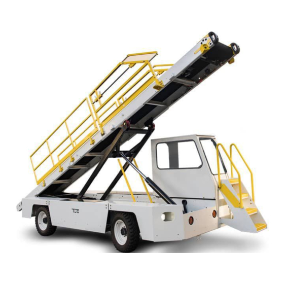
Warnings, Cautions, and Notes throughout this manual. 1.2 Purpose of Equipment The TUG Belt Loader Model 660-28 is designed to load and unload baggage, light freight, and mail into and out of the lower hold of aircraft. The conveyor may also be used to transfer freight from trucks or between any two points at the same or differing elevations. - Page 66 Mobile Belt Loader Model 660-28 Operation Operation Manual Section 1 1.3.2.2 Transmission Cooling System The transmission cooling system consists of a transmission oil cooler integrated into the engine radiator and features a thermostat bypass valve to allow the transmission to reach an operating temperature faster.
- Page 67 Operation Mobile Belt Loader Model 660-28 Section 1 Operation Manual When a manual lever is actuated, the lever mechanically shifts the spool valve position, porting fluid to that side of the lift cylinder to be pressurized. Spool Valve movement also opens a channel for the non- pressurized portion of the lift cylinder piston to allow unpressurized oil to return to the hydraulic oil reservoir through port on the valve manifold assembly and the return line hydraulic filter.
- Page 68 1.3.8 Air Intake and Exhaust Systems The TUG belt loader 660-28 is equipped with an air intake system that supplies clean air to the engine. It utilizes an air filter and intake hoses to route incoming air to the engine. The tow tractor utilizes an air filter that has a built-in tangential pre-cleaner ahead of the air filter element.
- Page 69 Operation Mobile Belt Loader Model 660-28 Section 1 Operation Manual • Enclosed cab frame • Side view mirrors located on the cab door • Front windshield wipers and washer system • Front window defrost system (optional) • Cab dome light •...
-
Page 70: Figure Operation-1-1: Collision Avoidance Module
Mobile Belt Loader Model 660-28 Operation Operation Manual Section 1 1.3.12.1 GM Inching Transmission The transmission has a different valve body which allows the Transmission Control Module (TCM) to apply the forward and reverse clutches independently within the transmission in order to control speed or stop the vehicle. -
Page 71: Figure Operation-1-2: Left Hand Pod And Sensor
Operation Mobile Belt Loader Model 660-28 Section 1 Operation Manual 1.3.12.4 Ultrasonic Sensors and Pods The sensors send out a high frequency sound signal and detect its return in order to determine the distance to an object in front of the conveyor. This signal is interpreted by the Collision Avoidance Module and is used to supply a distance value to the TCM in order to control the vehicle’s movement. -
Page 72: Figure Operation-1-4: Operator Indicator Light
Mobile Belt Loader Model 660-28 Operation Operation Manual Section 1 The operator indicator light is located on the left hand side of the conveyor near the front bumper. It is installed on the left hand sensor pod with a guard over the top of the light. -
Page 73: Figure Operation-1-6: Seat And Seat Switch
Operation Mobile Belt Loader Model 660-28 Section 1 Operation Manual The seat switch provides information to the TCM concerning whether or not an operator is present in the seat. if an operator is not present while the stem is active then the vehicle will come to a stop and the indicator lights will turn RED. - Page 74 Mobile Belt Loader Model 660-28 Operation Operation Manual Section 1 The brake pressure switch is located near the hydro-boost brake booster. The brake pressure switch share an input to the TCM which prevents FWD or REV engagement unless the brake pedal is depressed.
- Page 75 Operation Mobile Belt Loader Model 660-28 Section 1 Operation Manual 1.3.14.1 Standard Equipment/Features • Turn Signals • Brake Warning Light • Decals and Reflectors • Front and Rear Brakes 1.3.14.2 Optional Equipment/Features • Cold Weather Starting Aids • Enclosed Cab • Multi-functional Amber Beacon (rotating, flashing or strobe options) •...
- Page 76 Mobile Belt Loader Model 660-28 Operation Operation Manual Section 1 THIS PAGE INTENTIONALLY BLANK Operation - 1 - 12 CD397-Oper August 2018 (Rev B)
- Page 77 OPERATE THE UNIT. WARNING The TUG Model 660-28 is equipped with either a 4-cylinder Gasoline and LPG engine. The engine’s power is transmitted to the transmission, drive shaft, differential assembly, reduction gears and drive axle assembly. The vehicle operation employs standard disc brakes on the front wheels and drum brakes are provided on the rear wheels.
-
Page 78: Figure Operation-2-1: Operator's Compartment
Mobile Belt Loader Model 660-28 Operation Operation Manual Section 2 Figure Operation-2-1: Operator’s Compartment Operation - 2 - 2 CD397-Oper June 2019 (Rev C) - Page 79 Operation Mobile Belt Loader Model 660-28 Section 2 Operation Manual Table Operation-2-1: Operator Compartment Component Description Instrument/Dash Panel Contains the control switches The turn signal lever is used when making right or left turns. Turn Signal To indicate a right turn, push the signal control lever up or to indicate a left turn, push the lever down.
-
Page 80: Figure Operation-2-2: 660-28 Instrument Panel - Ford 2.5L
Mobile Belt Loader Model 660-28 Operation Operation Manual Section 2 2.2.1 Instrument/Dash Panel The following figure show the location of controls, indicators and components found on the instrument/ dash panels of the various engine options of the 660 Belt Loader. The corresponding tables give a brief description/summary of their operation. - Page 81 Operation Mobile Belt Loader Model 660-28 Section 2 Operation Manual Table Operation-2-2 Instrument Panel Description - Ford 2.5L (Continued) Control/Indicator Description This knob controls the engine speed only while the unit is in neutral and the parking brake is applied. Turn the knob Conveyor Hand Throttle counterclockwise and the engine will speed up. Depress the hand throttle knob and the engine will return to idle.
-
Page 82: Figure Operation-2-3: Cylinder Controls
Mobile Belt Loader Model 660-28 Operation Operation Manual Section 2 2.2.2 Conveyor Controls 2.2.2.1 Cylinder Controls Cylinder height controls in the operator’s compartment (located below driver’s seat) are limited to: 1. Front cylinder: raises / lowers the front of conveyor 2. Rear cylinder: raises / lowers the back of conveyor... - Page 83 Operation Mobile Belt Loader Model 660-28 Section 2 Operation Manual 2.2.2.3 Pilot-Operated Hydraulic Check Valves The pilot-operated hydraulic check valves are located on both lift cylinders and the reverse travel direction of the conveyor belt motor. The conveyor belt motor counted-balance valve prevents the free wheeling of the conveyor belt if the belt is stopped with the conveyor at an incline.
- Page 84 Mobile Belt Loader Model 660-28 Operation Operation Manual Section 2 2.3.2 Starting Instructions Procedures for maneuvering the vehicle to an aircraft are outlined below: OBSERVE ALL SAFETY PRECAUTIONS DISCUSSED IN THE SAFETY SECTION OF WARNING: THIS MANUAL. WARNING 2.3.2.1 Gas Engine Start Procedure 1. Apply park brake 2.
- Page 85 Operation Mobile Belt Loader Model 660-28 Section 2 Operation Manual 2.3.3 Driving Instructions The foot throttle is a conventional automobile accelerator connected to the ECM by electrical connection. • To increase speed, depress foot throttle. • To decrease speed, release foot throttle.
- Page 86 Mobile Belt Loader Model 660-28 Operation Operation Manual Section 2 2.3.5 Conveyor Maneuvering with Smart Sense 2.3.5.1 Activating Smart Sense The following steps are necessary to start movement on a Smart Sense equipped vehicle: 1. Sit in the seat. 2. Apply foot brake. 3. Start the engine. 4. Lower the park brake.
- Page 87 Operation Mobile Belt Loader Model 660-28 Section 2 Operation Manual 6. Make final conveyor boom height adjustments at this time by raising or lowering the conveyor to align with the aircraft door sill. If optional conveyor up/down inhibit valve is installed then the shifter must be placed into NOTE: NEUTRAL before the conveyor can be moved.
- Page 88 Mobile Belt Loader Model 660-28 Operation Operation Manual Section 2 6. Place the shifter into REV to slowly move away from the aircraft. The unit will not move forward if the shifter is moved to the FWD while the YELLOW light is NOTE: solid.
- Page 89 Operation Mobile Belt Loader Model 660-28 Section 2 Operation Manual 2.3.7 Park Brake Operation The park brake is located on the drive shaft or rear axle and is activated by an Orchelin over-center lever. With the park brake engaged, the loader will not move even when shifted into gear.
- Page 90 Mobile Belt Loader Model 660-28 Operation Operation Manual Section 2 2.4 Preventive Maintenance Only qualified personnel should service this unit. Do not attempt to carry out repairs CAUTION: unless you are a qualified maintenance mechanic. Report a faulty unit and do not use until repaired.
- Page 91 Operation Mobile Belt Loader Model 660-28 Section 2 Operation Manual Notes: CD397-Oper Operation - 2 - 15 June 2019 (Rev C)
- Page 92 Mobile Belt Loader Model 660-28 Operation Operation Manual Section 2 THIS PAGE INTENTIONALLY BLANK Operation - 2 - 16 CD397-Oper June 2019 (Rev C)
-
Page 93: Table Operation-3-1: Dimensions And Measurements
Operation Mobile Belt Loader Model 660-28 Section 3 Operation Manual Section 3: Specifications and Capabilities 3.1 Unit Dimensions Table Operation-3-1: Dimensions and Measurements Dimension Measurement Length 300 in. (762 cm) Width (excluding side bumpers) 78 in. (198.1 cm) Height 59 in. (149.9 cm) Wheelbase 110 in. (279.4 cm) Ground Clearance 7.5 in. -
Page 94: Figure Operation-3-1: Front Up, Rear Down
Mobile Belt Loader Model 660-28 Operation Operation Manual Section 3 170” (431.8 cm) 13” (33 cm) 224” (569 cm) Figure Operation-3-1: Front Up, Rear Down 168” (426.7 cm) 37” (94 cm) 257” (653 cm) Figure Operation-3-2: Front Up, Rear Up Operation - 3 - 2 CD397-Oper August 2018 (Rev B) -
Page 95: Figure Operation-3-3: Front Down, Rear Down
Operation Mobile Belt Loader Model 660-28 Section 3 Operation Manual 40” 36” (101.6 cm) (91.4 cm) 294” (747 cm) Figure Operation-3-3: Front Down, Rear Down 61” (154.9 cm) 31” (78.7 cm) 285” (724 cm) Figure Operation-3-4: Front Down, Rear Up 3.3 Specifications Table Operation-3-4: Specification Data Item Specification Battery 12 Volt Ground Negative Alternator... -
Page 96: Table Operation-3-5: Performance
The rear of the conveyor is set at 30 in. (76.2 cm) above ground level. The listed aircraft are compatible with the Mobile Belt Loader 660-28. The height measurements are from the IATA Airport Handling Manual (AHM) 904 “Aircraft Doors, Servicing Points and System Requirements for the Use of Ground Support Equipment.”... - Page 97 Operation Mobile Belt Loader Model 660-28 Section 3 Operation Manual Aircraft Compatibility Table Operation-3-6: (Continued) Aircraft Type Front Door Rear Door Airbus A300-300 136.2 in. (345.95 cm) 165 in. (419.1 cm) Airbus A340-200/300 137.4 in. (348.97 cm) 165.72 in. (420.93 cm) Airbus A340-500/600 143.28 in.(363.93 cm) 169.08 in.
- Page 98 Mobile Belt Loader Model 660-28 Operation Operation Manual Section 3 Aircraft Compatibility Table Operation-3-6: (Continued) Aircraft Type Front Door Rear Door BAC 1-11-500 69 in. (175.26 cm) 76 in. (193.04 cm) BAe ATP (J61) 107 in. (271.78 cm) 100 in. (254 cm) BAe (H.S.) - 748 102 in.
- Page 99 Operation Mobile Belt Loader Model 660-28 Section 3 Operation Manual Aircraft Compatibility Table Operation-3-6: (Continued) Aircraft Type Front Door Rear Door IL-62 107 in. (271.78 cm) 107 in. (271.78 cm) IL-62M 107 in. (271.78 cm) 103 in. (261.62 cm) IL-76T 79 in. (200.66 cm) 75 in. (190.5 cm) IL-86 113 in.
-
Page 100: Table Operation-3-7: Front Axle
Mobile Belt Loader Model 660-28 Operation Operation Manual Section 3 3.6 Engine 3.6.1 Ford MSG-425 2.5L Engine See Ford Owners, Operation and/or Service Manual for detailed engine data. NOTE: The LPG engine must use HD-5 or better quality fuel in order to avoid invalidating the warranty. -
Page 101: Table Operation-3-10: Front Axle
Operation Mobile Belt Loader Model 660-28 Section 3 Operation Manual 3.8 Axles 3.8.1 Front Axle Table Operation-3-10: Front Axle Component Specification Manufacturer Brierton Type Rigid Steering 3.8.2 Rear Axle Table Operation-3-11: Rear Axle Component Specification Manufacturer Newage or Axle Tech Type Rigid Drive 3.9 Steering System Table Operation-3-12: Steering System Component Specification Type Hydrostatic Emergency Steering Pump 12V DC 3.10 Hydraulic System... -
Page 102: Table Operation-3-15: Hydraulic Fluids
Mobile Belt Loader Model 660-28 Operation Operation Manual Section 3 Table Operation-3-14: Hydraulic System Components Component Description Rating Hydraulic Connectors Gates brand Mega Crimp 3000 psi (20.68 mPa or 204.14 atm) Hydraulic Hoses Gates brand Mega 3000 3250 psi (22.41 mPa or 221.15 atm) -
Page 103: Figure Operation-3-5: Capscrew Examples
Standard Capscrew Figure Operation-3-5: Capscrew Examples The following torque tables apply to graded metric and standard fasteners used on the 660-28. The listed values apply to bolts threaded into either nuts or tapped holes in iron or steel. These torque values are not a replacement for torque values specified elsewhere in this manual. -
Page 104: Table Operation-3-17: Torque Values For Metric Fasteners
Mobile Belt Loader Model 660-28 Operation Operation Manual Section 3 3.12.2 Metric Fasteners Table Operation-3-17: Torque Values for Metric Fasteners Nominal Pitch Class 8.8 Class 10.9 Class 12.9 Diameter (mm) (Nm) (Nm) (Nm) (mm) 2.576 3.661 4.339 5.288 7.457 8.813 8.948 12.745 14.914 14.914 21.422 24.947 1.25 21.693 31.048 36.200 42.844 61.283... - Page 105 Operation Mobile Belt Loader Model 660-28 Section 3 Operation Manual Table Operation-3-18: Torque Values for Graded Bolts (Continued) Nominal Threads SAE J429 Grade 5 SAE J429 Grade 8 Diameter (in.) per Inch (ft-lbs) (ft-lbs) 5/16 7/16 9/16 1 1/4 1545 1 1/2 1657 2688 Fine Thread Series 5/16 7/16 9/16 1 1/4 1055 1710 1 1/2...
- Page 106 Mobile Belt Loader Model 660-28 Operation Operation Manual Section 3 THIS PAGE INTENTIONALLY BLANK Operation - 3 - 14 CD397-Oper August 2018 (Rev B)
-
Page 107: Figure Operation-4-1: 660-28 Tie Down Points
Secure the unit in place using the tie down points. 4.1.1 Tie-Down Points (Truck Shipping) The 660-28 is secured through a single D-ring located at the front and a single rear D-ring at the rear of the unit Figure Operation-4-1 660-28 Tie Down Points. No other tie down points are authorized. - Page 108 Mobile Belt Loader Model 660-28 Operation Operation Manual Section 4 4.1.2 Lifting (Truck Shipping) TO AVOID INJURY TO PERSONNEL OR DAMAGE TO EQUIPMENT, ALWAYS USE LIFTING EQUIPMENT, SAFETY JACKS, AND CHAINS WITH A SAFE MINIMUM WARNING: CAPACITY OF ONE AND A HALF (1.5)TIMES THE WEIGHT OF THE VEHICLE BEING LIFTED.
-
Page 109: Figure Operation-4-2: Conveyor Stacking Materials
Operation Manual 4.1.6 Conveyor Belt The 660-28 may be shipped as a single unit or the chassis and conveyor belt can be shipped separately. When shipping or storing two or more conveyor units, space can be saved by removing and stacking the conveyor belts. -
Page 110: Figure Operation-4-4: Wooden Support Placing
Mobile Belt Loader Model 660-28 Operation Operation Manual Section 4 4. Space the three (3) wooden supports evenly along the length of the conveyor; rubber side face down (Figure Operation-4-4 Wooden Support Placing). Figure Operation-4-4: Wooden Support Placing 5. Lower the conveyor on the three (3) wooden supports, ensure both conveyors sit exactly on top of each other (Figure Operation-4-5 Conveyor Belt Placement). -
Page 111: Figure Operation-4-6: Bubble Wrap
Operation Mobile Belt Loader Model 660-28 Section 4 Operation Manual 6. Place double-thickness bubble wrap at the three (3) wooden supports (Figure Operation-4-6 Bub- ble Wrap). Figure Operation-4-6: Bubble Wrap 7. Place the tie down straps around the conveyors over the bubble wrap (Figure Operation-4-8 Tied Down Conveyor Coils). -
Page 112: Figure Operation-4-8: Tied Down Conveyor Coils
Mobile Belt Loader Model 660-28 Operation Operation Manual Section 4 10. Tie wrap the coiled cords to the conveyor (Figure Operation-4-8 Tied Down Conveyor Coils). Figure Operation-4-8: Tied Down Conveyor Coils 11. Individually bubble wrap each of the pinch guards and place them together (Figure Operation-4-9 Pinch Guard Wrap and Placement). -
Page 113: Figure Operation-4-11: Rear Of Unit Tie Down
Operation Mobile Belt Loader Model 660-28 Section 4 Operation Manual 15. Use tie down straps at the tie down points to secure the front and rear of the unit. Figure Operation-4-11: Rear of Unit Tie Down 16. Chock all four (4) wheels. Figure Operation-4-12: Chocked Wheels 4.1.7 Checks On tractors so equipped, ensure the in-line fuel shut-off valve is open. - Page 114 Mobile Belt Loader Model 660-28 Operation Operation Manual Section 4 4.2 Preparation for Operation ENSURE ALL FUEL LINES ARE PROPERLY CONNECTED FROM TANK TO FUEL WARNING: PUMP TO INJECTOR PUMP. WARNING 4.2.1 Tie-Down Points (Truck Shipping) Remove tie-downs from the forward and rear of the belt loader.
- Page 115 (Figure Operation-4-15 Removing “Carrier” Belt Loader). Figure Operation-4-15: Removing “Carrier” Belt Loader 7. Drive belt loader chassis under the conveyor. 8. Ensure the conveyor is installed as outlined in the 660-28 Maintenance Manual. CD397-Oper Operation - 4 - 9 August 2018 (Rev B)
- Page 116 Connect battery terminals to battery posts. 4.2.8 Additional Components 1. Perform Pre-operational checks as listed in the 660-28 Operation Manual, and start the unit. 2. Operate the unit under NO LOAD conditions until it is clear that all of the systems are operating correctly before returning it to service.
- Page 117 Operation Mobile Belt Loader Model 660-28 Section 4 Operation Manual Notes: CD397-Oper Operation - 4 - 11 August 2018 (Rev B)
- Page 118 Mobile Belt Loader Model 660-28 Operation Operation Manual Section 4 THIS PAGE INTENTIONALLY BLANK Operation - 4 - 12 CD397-Oper August 2018 (Rev B)
- Page 119 Operation Mobile Belt Loader Model 660-28 Section 5 Operation Manual Section 5: Storage Following are storage procedures for short term and long term storage periods. In either case, store the vehicle in a clean, dry place with protection from extreme temperatures and/or high humidity.
- Page 120 Mobile Belt Loader Model 660-28 Operation Operation Manual Section 5 5.1.1.5 Lubrication Lubricate all points with specified grease, oil, etc. See Lubrication schematic in the maintenance manual. 5.1.1.6 Battery Disconnect battery terminals. Keep the battery fully charged during storage. 5.1.1.7 Fluid Levels All fluid levels should be checked and topped off as necessary.
- Page 121 Operation Mobile Belt Loader Model 660-28 Section 5 Operation Manual 5.3 Long Term Storage Long term storage applies to equipment that will be stored for a period that exceeds 120 days. This section provides general guidelines for preparing the engine and engine components for long term storage.
- Page 122 Mobile Belt Loader Model 660-28 Operation Operation Manual Section 5 5.3.1.2 Transmission Refer to the manufacturer’s recommendation contained in the transmission service manual. CAUTION: Prolonged storage may be detrimental to transmission seals. If the engine is without the transmission, then spray flywheel and ring gear with one part recommended engine oil, and one part Stoddard Solvent, or equivalent.
- Page 123 9. Using a bar or turning tool, turn the engine in its normal direction of rotation. 10. Ensure there are no hydraulic locks or resistance. 5.4.4 Transmission Refer to the manufacturer’s recommendations contained in the Vendor section of 660-28 Maintenance manual. 5.4.5 Drive Axle Refill the drive axle, if needed.
- Page 124 Mobile Belt Loader Model 660-28 Operation Operation Manual Section 5 5.4.6 Pre-Operation Checks 1. Perform Pre-operational checks. 2. Remove the warning tag from the cab, and start the unit. 3. Start the unit. The unit may run rough and smoke for a few minutes until it has cleared all the preservatives NOTE: from the system.
- Page 125 Operation Mobile Belt Loader Model 660-28 Section 5 Operation Manual NOTES CD397-Oper Operation - 5 - 7 August 2018 (Rev B)
- Page 126 Mobile Belt Loader Model 660-28 Operation Operation Manual Section 5 THIS PAGE INTENTIONALLY BLANK Operation - 5 - 8 CD397-Oper August 2018 (Rev B)
- Page 127 Operation Mobile Belt Loader Model 660-28 Section 5 Operation Manual THIS PAGE INTENTIONALLY BLANK CD397-Oper Operation - 5 - 9 August 2018 (Rev B)
- Page 128 TUG Equipment A business of Textron Ground Support Equipment, Incorporated 4105 Royal Drive Kennesaw, Georgia, 30144 (USA) Telephone: +1 770 499 6100...
Need help?
Do you have a question about the 660-28 and is the answer not in the manual?
Questions and answers