Table of Contents
Advertisement
0 12 - 0 89 5 0 F
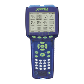
Users' Guide
• Using the Xplorer GLX
Standalone
• Using the Xplorer GLX
with a Computer
• Sample Activities
New Features:
•
File storage on USB flash drive, p. 83
•
Update firmware from flash drive, p. 93
•
Instant data monitoring in Digits and
Meter displays, pp. 37 & 38
•
Voice and Text Data Annotation, p. 25
(more on page ii)
Advertisement
Table of Contents

Related Manuals for PASCO Xplorer GLX


Summary of Contents for PASCO Xplorer GLX
- Page 1 Users’ Guide • Using the Xplorer GLX Standalone • Using the Xplorer GLX with a Computer • Sample Activities New Features: • File storage on USB flash drive, p. 83 • Update firmware from flash drive, p. 93 • Instant data monitoring in Digits and Meter displays, pp.
-
Page 2: Table Of Contents
Copyright The PASCO scientific Xplorer GLX Users’ Guide is copyrighted with all rights reserved. Permission is granted to non-profit educational institutions for reproduction of any part of this manual, providing the reproductions are used only in their laboratories and classrooms, and are not sold for profit. Reproduction under any other circumstances, without the written consent of PASCO scientific, is prohibited. - Page 3 (But don't plug in the AC adapter when the battery in not installed.) See page 95 of the Users' Guide for more information. TAPE THIS SHEET TO THE INSIDE LID OF THE GLX STORAGE BOX OR POST IT WHERE THE GLX WILL BE STORED. ® Visit www.pasco.com/glx to download the latest GLX firmware update and Users’ Guide.012-08950F...
- Page 5 ... . 97 Overview of the GLX ....6 Chapter 6: Using the Xplorer GLX Chapter 1: Displays with a Computer Graph .
- Page 7 P a r t 1 : U s e r s ’ G ui d e...
- Page 9 An optional mouse, keyboard, or printer can be connected to the Xplorer GLX’s USB ports. The Xplorer GLX contains an integrated speaker for sound generation and a stereo signal output port for optional headphones or amplified speakers.
- Page 10 F) Two Fast-response Temperature Probes (-10 to 70 °C) B) Xplorer GLX C) AC Power Adapter G) Voltage Probe (-10 to +10 V) D) Registration Card H) USB Host-connection Cable E) Getting Started with the Xplorer GLX CD-ROM Poster (not pictured)
- Page 11 X p l o r e r G L X U s e r s ’ G u i d e Quick Start Getting started with the GLX is easy—simply plug in the AC adapter, connect one of the included sensors, and collect data. In the example below, you will start the GLX and collect temperature data.
- Page 12 Temperature Probes Connect the included fast-response probes or other Voltage Probe PASCO temperature probes to the two temperature ports on the left side of the PASPORT GLX. The range is -10 to +70 °C with fast-response probes, or -10 to +135 °C Sensor Ports with stainless steel probes.
- Page 13 X p l o r e r G L X U s e r s ’ G u i d e the GLX. Do not connect a voltage source until after the probe is connected to the GLX; remove any voltage sources before disconnecting the probe. Sound Sensor To configure the GLX’s microphone as a sound sensor, press together to enter the Sensors screen;...
- Page 14 O v e r v i e w t h e G L X Auto Power Off Timed Auto Power Off If it is running on battery power, the GLX will auto- The GLX is considered idle when • the GLX is not collecting data, matically save your data and shut down after a certain amount of continuous idle time (5 minutes by default).
- Page 15 X p l o r e r G L X U s e r s ’ G u i d e recording, you must press and hold until you hear three beeps again. Data recording will stop when you release Alternative Recording Modes If you have put the GLX into Manual Sam- pling mode (see page 57), it will not start recording when you press ;...
- Page 16 O v e r v i e w t h e G L X Digits This screen is useful for displaying live data as they are collected from sensors and calculations. Up to six data sources can be displayed simultaneously. See page 37 for more information.
- Page 17 X p l o r e r G L X U s e r s ’ G u i d e Top Bar Home Icon Memory Gauge The Top Bar is the part of the Home Screen that is always visible from anywhere GLX Name Time and Date or File Name...
- Page 18 O v e r v i e w t h e G L X...
- Page 19 X p l o r e r G L X U s e r s ’ G u i d e Cha p te r 1 : Disp lays The GLX has four screens for displaying data: Graph, Table, Digits, and Meter. This chapter will describe the structure and use of each display.
- Page 20 G r a p h Active Fields Run Number Units Data Source Data Source Units Active fields of the Graph Active fields are the areas on the Graph (and other display screens) through Selecting a field with the keypad which you control what data are shown. When you select an active field, a menu opens containing choices of data source, units, or run number.
- Page 21 X p l o r e r G L X U s e r s ’ G u i d e Choosing Data to Display Data Source A graph is generated from two data sources: one on the vertical axis and one on the horizontal axis. The possible types of data source are •...
- Page 22 G r a p h In normal mode, one data set is displayed at a time. See “Two Runs” on page 24 for instructions on displaying two runs simultaneously. The next-to-last option in the run number menu is Delete Run, which deletes the currently displayed run.
- Page 23 X p l o r e r G L X U s e r s ’ G u i d e In Scale mode, the left and right arrow keys compress and stretch the Graph hor- Scale Stretch Mode vertically izontally;...
- Page 24 G r a p h When you select a tool from the Tools menu, a check mark ( ) appears next to To select a tool from the Tools it. To turn off a tool, select it from the menu again, which removes the check menu: mark and returns the Graph to normal mode.
- Page 25 X p l o r e r G L X U s e r s ’ G u i d e Negative DX and DY Positive DX and DY When the cursors swap places, the signs of ∆X and ∆Y change Slope Tool Select the Slope Tool from the Tools menu to measure the slope of Slope a tangent line at one point on the data plot.
- Page 26 G r a p h When the Linear Fit is turned on, the special option Create Calculation from Lin- ear Fit appears in the Tools menu (see page 22). Linear Fit can be useful even when the graphed data are not linear (qua- dratic or exponential, for instance).
-
Page 27: Swap Cursors
X p l o r e r G L X U s e r s ’ G u i d e The Trigger affects data recording even if you are not viewing the Graph. If you For information about multiple Graph have set up two or more triggers on separate Graph pages, data recording will pages, see “New Graph Page”... -
Page 28: Automatic Calculation Creation From Linear Fit
G r a p h and other tools are applied. In cases where the two data sets are scaled separately, the active that is scaled. To toggle data without opening the menu: hold , press , and release both Toggle Data Shortcut keys. - Page 29 X p l o r e r G L X U s e r s ’ G u i d e After you press , the GLX begins collecting and displaying a series of data bursts (each burst is enough data fill the Graph from left to right). If you have enabled the Trigger, the GLX waits for the trigger condition to be met before col- lecting each burst.
- Page 30 G r a p h Typically you would use Two Measurements mode to display data from two different sources, but you can also use it to display two runs from the same source. Select the same source from both data source fields, and different runs from each run number field.
-
Page 31: Zoom Tool
X p l o r e r G L X U s e r s ’ G u i d e Print If there is a printer connected to the GLX, select Print from the Graphs menu to print the currently displayed graph page. Print All Select Print All to print all of the graph pages. - Page 32 G r a p h A note with the Data Cursor positioned on it To make the Data Cursor jump directly to a note, hold and press one of the arrow keys. Press plus the left or right arrow key to make the cursor jump to the next visible note in either direction;...
- Page 33 X p l o r e r G L X U s e r s ’ G u i d e Note Editor Dialog Box Text Portion Audio Portion Audio Duration Audio Size Note Editor Dialog Box The Note Editor opens when you select Edit Note from the Annotation menu. The text portion of the note appears in the upper half of the box.
- Page 34 T a b l e Table Use the Table to display data, edit or enter data manually, and display statistics on data sets. The Table can show up to four columns of numeric or text data. To Open the Table From the Home Screen, do one of the following: press , the function key below the Table icon;...
- Page 35 X p l o r e r G L X U s e r s ’ G u i d e If the chosen data source does not contain data, the data source name will appear at the top of the column, but the cells of the column will remain empty until data collection starts.
- Page 36 T a b l e The chosen statistics will be displayed at the bottom of every column. To choose a statistic, select it from the menu. To turn off a displayed statistic, select it To select a statistic from the Statis- tics menu: again.
- Page 37 X p l o r e r G L X U s e r s ’ G u i d e F4 Tables Tables Menu From the Tables menu, you can select to display one, two, three, or four col- umns.
-
Page 38: Export Data To Text File
T a b l e of one column will cause all of them to change. To turn Lock Run Selection off See “Run Number” on page 29 for or on, select it from the Tables menu. instructions on changing the run number displayed in a column. - Page 39 X p l o r e r G L X U s e r s ’ G u i d e Entering Numeric Data In a New Column In the new editable column, you will see a box around the first cell and a blinking cursor inside the cell. Box with blinking Type a number on the keypad (or attached keyboard), then press...
- Page 40 T a b l e Naming Manually Entered Data and Adding Units By default, new editable data sets are named “Data 1,” “Data 2,” etc., and they do not have defined units. To change the name and add units, open the data source menu and select Data Properties.
- Page 41 X p l o r e r G L X U s e r s ’ G u i d e Use the arrow keys to move the Navigating Box Position the Navigating Box on a cell where you would like to enter or edit data, then press to make the Editing Box appear.
- Page 42 T a b l e Graphing Manually Entered Data Numeric Data After you have created an editable numeric data set in the Table, you can display it in the Graph. In the Graph, select the editable data from the horizontal or vertical data source menu (see page 15). Text Data A text data set can be displayed on the horizontal axis of the Graph.
- Page 43 X p l o r e r G L X U s e r s ’ G u i d e Di gits D isp lay Use the Digits display to show data from up to eight data sources. This display monitors and shows live data even when the GLX is not recording.
- Page 44 M e t e r Mete r The Meter display simulates an analog meter with a needle that deflects in pro- portion to a sensor measurement or sensor-based calculation. This display moni- tors and shows live data even when the GLX is not recording. Data Source Units Meter display...
- Page 45 X p l o r e r G L X U s e r s ’ G u i d e Cha p te r 2 : Utility Scr ee ns This chapter describes the Output screen, Calculator, Notes screen, and Stopwatch. O utp ut The Output screen is the control panel for generating sound through the GLX’s built-in speaker or through headphones or amplified stereo speakers connected to...
- Page 46 O u t p u t Output Settings The output settings in the Output screen can also be changed in the Audio Settings dialog box, accessed Output Device from the Settings screen (see page 87). When you change the settings in one Highlight the Output control and press to select the output device that you location, they are automatically updated...
- Page 47 X p l o r e r G L X U s e r s ’ G u i d e Ca lcul ato r You can use the GLX Calculator like a regular calculator for finding the result of a simple expression, like a graphing calculator for plotting equations, and for per- forming operations, in real time, on streams of data collected from sensors and on sets of manually entered data.
- Page 48 C a l c u l a t o r • Press the up arrow key to put the cursor back on the above expression and modify it to read: 9 * ( 9 + 3 ) When you type something into the middle of an existing expression, the new Õ...
- Page 49 X p l o r e r G L X U s e r s ’ G u i d e When there is more than one definition for the same symbol, the calculator uses the first definition. To avoid confusion, do not define a symbol more than once.
- Page 50 C a l c u l a t o r • A symbol does not have to be a single letter. The Calculator will recognize any text string (without spaces) as a symbol, including text strings that con- tain numerals. (To type text on the keypad, see “Num Lock” on page 50.) Examples of text strings used as symbols in algebraic calculations Graphing Equations...
- Page 51 X p l o r e r G L X U s e r s ’ G u i d e See “Data Source” on page 15 for more information about selecting data in the Graph. In the Graph, select the calculation from the data source menu •...
- Page 52 C a l c u l a t o r • Open the calculator. On the first blank line, enter: For the d symbol, press twice and select it from the second Functions menu. ° d = [ T e m p e r a t u r e ( C ) ] - 2 0 To select Temperature from the Instead of typing “[Temperature (°C)]”, select it from the [Data] menu.
- Page 53 X p l o r e r G L X U s e r s ’ G u i d e Plot the calculation on the horizontal axis in place of Time to create the graph shown below. (See page 28 for instructions on selecting data for the horizontal axis.) Convert Units of Measure Most of the sensors used with the GLX are pro- grammed with SI units (or the International System of Units) and, in some cases,...
- Page 54 C a l c u l a t o r • The position versus time graph of an object in free fall (below right) exhibits a typical quadratic relationship. The object was dropped from a height of 0.79 m, with the release occurring 2.2 s after the start of data collection. The graph can be linearized (as shown below right) by replacing Time on the hor- izontal axis with the calculation ( - 2.2)
- Page 55 X p l o r e r G L X U s e r s ’ G u i d e Special functions, output-control functions, and logic operators and functions are typically used to control the GLX’s digital and audio output. See “Output- control Calculations”...
-
Page 56: Output-Control Calculations
C a l c u l a t o r F4 Edit Menu Press (or click Edit) to open the Edit menu, which contains the options described below. Num Lock When Num Lock is on (which it is by default), an icon ( ) appears in the lower right corner of the screen. - Page 57 AdapterChannel, state) Use the outputstate func- tion to switch on or off a Digital Relay connected through a Digital Adapter. The Digital Relay is PASCO part CI-6462. The Digital Adapter is PASCO part PS-2159. The first argument of the function, GLXPort, can equal 1, 2, 3, or 4; it identifies the port that the Digital Adapter is connected to.
- Page 58 C a l c u l a t o r outputfreq(Channel, frequency) Use the outputfreq function to set the fre- quency of the audio output signal. The first argument, Channel, can equal 1 (for left) or 2 (for right) and identifies which channel is to be controlled. The second argument, frequency, sets the frequency, in Hz, of the output signal.
- Page 59 X p l o r e r G L X U s e r s ’ G u i d e No tes Sc ree n Use the Notes screen to record experiment instructions, information about the sensors and displays that you have set up, notes on recorded data, or any other text information.
- Page 60 S t o p w a t c h Sto pw at ch With the Stopwatch screen, you can use the GLX like a conventional stopwatch. To Open the Stopwatch From the Home Screen, do one of the following: use the arrow keys to highlight the Stopwatch icon, then press ;...
- Page 61 X p l o r e r G L X U s e r s ’ G u i d e Cha p te r 3 : Se t t ing s an d F il es Sen sor s S cr een In many cases, the sensor set-up process requires nothing more than simply plug- ging in a sensor.
- Page 62 S e n s o r s S c r e e n Sensor Settings To change any of the settings, use the arrow keys to highlight the settings and press If you are using a mouse, click the desired setting. Sample Rate Unit Select Sample Rate Unit to choose how the sampling rate To select Sample Rate Unit...
- Page 63 X p l o r e r G L X U s e r s ’ G u i d e Zero Automatically On Start This setting appears for sensors that support zeroing (such as acceleration, rotary motion, and drop counter sensors). The three choices are “On,”...
-
Page 64: Built-In Sound Sensor
S e n s o r s S c r e e n F3 Microphone The Microphone menu contains options for setting how the GLX uses its built-in microphone. The selected option is indicated by a check mark ( ) appearing next to it in the menu. -
Page 65: Data Collection With Scienceworkshop Sensors
X p l o r e r G L X U s e r s ’ G u i d e F4 Sensors The Sensors menu contains the following options for adding, removing, and cali- brating sensors. To select an option from the Sensors menu Add Select this option to set up a sensor without physically connecting it. -
Page 66: Cell-Selective Manual Sampling With Table Display
S e n s o r s S c r e e n Manual Sampling Mode In Manual Sampling mode, the GLX records a single sample from each measure- ment only when you trigger it by pressing . Follow these steps to set up Man- ual Sampling mode and record data. - Page 67 X p l o r e r G L X U s e r s ’ G u i d e Press . The GLX starts measuring, but not recording. A blinking flag icon ( ) appears in the upper right-hand corner. Another flag icon appears at the left side of the first table row.
- Page 68 To Open the Timing Screen The Timing screen usually launches automatically when you connect a switch- or counting-type digital sensor to the GLX through a Photogate Port or a Digital Photogate Port is PASCO part Adapter. PS-2123A. Digital Adapter is PASCO part PS-2159.
- Page 69 X p l o r e r G L X U s e r s ’ G u i d e measured from the start of data collection to the midpoint of the sequence. From these measurements and user-entered (or default) constants, the GLX derives other measurements such as position, velocity, and acceleration.
- Page 70 T i m i n g S c r e e n Set Time in Gate and Velocity in Gate to “Visible.” Pretend that you have a cart with a 5 cm flag on it; set the Flag Length con- stant to 0.05 m.
- Page 71 Velocity and angular Acceleration are calculated based on the time intervals between the changes in angle. Free Fall Adapter Use this timer with PASCO part ME-9207B. The constant, Height Of Fall, is the distance (in meters) from the release mechanism to the receptor pad.
- Page 72 Time of Flight Use this timer with a projectile launcher, two photogates, and a Time-of-Flight Accessory. The constant, Photogate Spacing, is the distance (in The Time-of-Flight Accessory is PASCO part ME-6810. Projectile meters) between the centers of the photogates. Launchers include ME-6800 and ME-6801. A Photogate Bracket, part The measurements are Initial Velocity and Time Of Flight.
- Page 73 Sensors screen (see page 55). Relay Control To set up the GLX for control of a Digital Relay through a The Digital Relay is PASCO part CI-6462. Digital Adapter, connect the relay to the adapter and connect the adapter to the...
- Page 74 T i m i n g S c r e e n GLX. The Add menu will open automatically; select Relay Control. Both ports of the adapter will be configured for Relay Control (though they are controlled separately), so you can connect a second relay to the adapter with no additional set-up required.
- Page 75 X p l o r e r G L X U s e r s ’ G u i d e Da ta P r oper t ies Data Properties dialog box Every data set and data source in the GLX has data properties, which control how the data are displayed in the Graph, Table, and other screens.
- Page 76 D a t a P r o p e r t i e s See “Multipress Text Input Mode” on page 90 for instructions on using the keypad to enter text. Note that changing the name of the units will have no effect on the actual data. For instance, if you change the name of the Temperature units from “°C”...
- Page 77 X p l o r e r G L X U s e r s ’ G u i d e Ca lib rat ion Some of the sensors that you use with the GLX can be calibrated in the Calibra- tion dialog box, which is accessible through the Sensors screen.
- Page 78 C a l i b r a t i o n Pt 2 DInput DInput Pt 1 Slope = DOutput DOutput Offset Output Data Two points, Pt 1 and Pt 2, define the line. In the two-point calibration procedure, each point is reset by associating a known standard value (for instance, the pH of a buffer solution) with a raw input measurement that the sensor sends to the GLX when it is in that standard.
- Page 79 X p l o r e r G L X U s e r s ’ G u i d e One-Point Offset In a one-point offset calibration, you reset only one point. The line shifts so that it intersects the new point, but its slope does not change. calibration point calibration...
- Page 80 C a l i b r a t i o n Sensor Field Measurement Field Single/All Field Calibration Type Arrow indicating that additional fields can be displayed with the down arrow key Pt 1 Standard Value Pt 1 Sensor Input Value Pt 2 Standard Value Pt 2 Sensor Input Value Arrow indicating that...
- Page 81 X p l o r e r G L X U s e r s ’ G u i d e Because they are not needed, the fields for Pt 1 are hidden when the 1 Point Slope calibration type is selected, and the fields for Pt 2 are hidden when the 1 Point Offset calibration type is selected.
- Page 82 C a l i b r a t i o n Press to read the sensor input value of Pt 1. Note that the Raw Input Measurement has been automatically entered into the Pt 1 Sensor Input Value field, and the standard value is now displayed as the Calibrated Output Measurement.
- Page 83 X p l o r e r G L X U s e r s ’ G u i d e Enter standard Enter the value of the standard in the Standard Value field for Pt 2. value here Observe the Raw Input Measurement displayed near the bottom right corner of the screen and wait until it has stabilized.
- Page 84 D a t a F i l e s S c r e e n Da ta F ile s S cre en Collected data, calculations, notes, display configurations, and sensor settings are all stored in the GLX’s memory. You can save data in a file during or after an experiment, or save a file without data to use as the starting point of an experi- ment.
- Page 85 X p l o r e r G L X U s e r s ’ G u i d e For more information on the RAM and Flash data-storage locations, see page 82. Navigating in the File List When the focus is on the File List, a highlight appears on one of the entries. Press Selected folder the up and down arrow keys to move the highlight.
- Page 86 D a t a F i l e s S c r e e n Mouse Navigation If you are using a mouse, click RAM or Flash to view the File List for each folder. Click the file or file component to highlight it. Click the icon to the left of a file to show or hide the file contents.
- Page 87 X p l o r e r G L X U s e r s ’ G u i d e If changes have been made to the current active file since it was last saved, a dia- log box will ask if you want to save the file. Select Yes ( ) to save the current active file before it is unloaded.
- Page 88 D a t a F i l e s S c r e e n RAM and Flash The GLX has two types of memory for file storage: RAM and Flash, represented by two folders in the Data Files screen. By default, files are saved in the RAM folder.
-
Page 89: Usb Flash Drive Support
X p l o r e r G L X U s e r s ’ G u i d e Using the GLX with a USB Storage Device If you have a USB storage device (such as a USB flash drive), you can use it to The USB storage device must be for- add storage capacity to your GLX, back up data, and transfer data to another matted using the FAT16 or FAT32 file... -
Page 90: Glx-To-Glx Data Transfer, P
D a t a F i l e s S c r e e n GLX-to-GLX File Transfer To transfer files directly between two GLXs, connect the larger USB port of one GLX to the smaller USB port of the other GLX using the included USB host- connection cable. - Page 91 X p l o r e r G L X U s e r s ’ G u i d e Set ti ngs Scr ee n Settings screen The Settings screen contains the controls for how the GLX environment looks and acts.
- Page 92 S e t t i n g s S c r e e n Back Light From anywhere in the GLX environment, the easiest way to turn the screen’s back light on or off is to hold and press You can also operate the back light from the Settings screen. Highlight Back Light and press to open the menu.
- Page 93 X p l o r e r G L X U s e r s ’ G u i d e Settings Screen Function Keys F1 Set Date and Time The date and time are set automatically when you connect the GLX to a com- puter running DataStudio.
- Page 94 S e t t i n g s S c r e e n...
- Page 95 X p l o r e r G L X U s e r s ’ G u i d e Cha p te r 4 : Na vi ga t ion an d I n pu t Da ta S ou rce M enu s The axes of the Graph, the columns of the Table, the sections of the Digits dis- play, and the Meter each have a data source field, which you access to choose what data to display.
- Page 96 For most users, text entry is faster and easier with a USB keyboard connected to PASCO part PS-2540 or PS-2541 the GLX. A keyboard also allows the input of capital letters in areas of the GLX environment where Shift and Caps Lock are not available.
- Page 97 For an up-to-date list menu. of compatible printers, visit www.pasco.com or contact PASCO tech- To install a printer on the GLX, simply connect it to the GLX’s USB port using nical support at: the cable that came with your printer. Drivers for compatible printers are factory support@pasco.com...
- Page 98 P r i n t i n g...
-
Page 99: Update Firmware From Usb Flash Drive
O pe ra ti on Fir mw ar e U pd ate From time to time, PASCO issues a free update to the firmware that runs on the GLX. Updates include new and improved features and bug fixes. Send in the reg- istration card that you received with your GLX, or register at www.pasco.com/glx to be notified of new updates. - Page 100 B a t t e r y a n d P o w e r While charging, the GLX monitors its own temperature to prevent overheating. The maximum recommended ambient temperature for charging is 32 °C (90 °F) without sensors, or 28 °C (82 °F) with four maximum-load sensors connected.
- Page 101 X p l o r e r G L X U s e r s ’ G u i d e Manual Internal Disconnection If you anticipate that your GLX will be left unused and unplugged for more than a month, manually put it into deep sleep mode. This will make it more likely that the battery will be charged the next time you use it.
- Page 102 See “Data Files Screen” on charge-discharge cycle: Connect the AC adapter and allow the battery to fully page 78 and “Using the Xplorer GLX with charge. Then disconnect the AC adapter, plug in a sensor, start data collection, a Computer” on page 99 for instructions.
- Page 103 X p l o r e r G L X U s e r s ’ G u i d e Connect the GLX to a computer running DataStudio to re-install sensor data sheets. Follow these steps to reset system settings to factory defaults and delete saved data in RAM and Flash.
- Page 104 O p e r a t i n g T e m p e r a t u r e...
- Page 105 DataStudio. See “GLX Simulator” on page 103. that you received on a CD-ROM with your GLX or download the most recent version from www.pasco.com. Connecting the GLX to a Computer To computer With the GLX powered on, use the USB host-connection cable (included with the GLX) to connect the smaller USB port of the GLX to the USB port of your computer.
- Page 106 G L X w i t h D a t a S t u d i o Transferring Files GLX File Manager If DataStudio detects a GLX with new files saved on it, it automatically opens the GLX File Manager. You can also manually open the GLX File Manager with these steps.
- Page 107 X p l o r e r G L X U s e r s ’ G u i d e to select a folder on your computer and a file name for the downloaded copy of the file. GLX files saved on your computer’s disk have the file extension .glx. They can be opened with DataStudio or copied to another GLX.
- Page 108 G L X w i t h D a t a S t u d i o DataStudio, the file is translated into a DataStudio file. Most components of the GLX file, listed below, appear in the new DataStudio file. •...
- Page 109 X p l o r e r G L X U s e r s ’ G u i d e G LX Si mula tor When you install DataStudio version 1.9.5 (or later) on a Windows computer, a second piece of software, the GLX Simulator, is also installed. To start the simu- lator, run the executable file XplorerGLX.exe.
- Page 110 G L X S i m u l a t o r Simulated data from the Virtual Motion Sensor Screen Capture Click the Copy Screen button to copy an image of the Simulator’s screen to the computer’s clipboard. The image can then be pasted into another application (such as a word processor) by selecting Paste from that application’s Edit menu.
- Page 111 P a r t 2 : Sample Activities The following pages contain step-by-step instructions for science activities and experiments that can be done with the GLX, its included temperature and voltage probes, and commonly available supplies; no PASPORT sensors are required.
- Page 113 G L X U s e r s ’ G u i d e Activi ty 1 : Ca lor ime tr y Equipment Quantity Xplorer GLX Fast-response Temperature Probes 20 g Brass Masses Styrofoam Cups String Hot Water (50 to 70 °C)
- Page 114 C a l o r i m e t r y GLX Set-Up Connect the temperature probes. Optional: after connecting the probes, perform the alignment calibration Connect the probe in Cup 1 to one of the temperature ports on the left described on page 77.
- Page 115 X p l o r e r G L X U s e r s ’ G u i d e Create a new graph page showing only the temperature in Cup 2 versus time. Press to open the Graphs menu; press to select New Graph Page.
- Page 116 C a l o r i m e t r y...
- Page 117 G L X U s e r s ’ G u i d e Activi ty 2 : Me lting Po in t De p ressi on Equipment Quantity Xplorer GLX Fast-response Temperature Probes Test Tubes Test Tube Rack Deionized Water...
- Page 118 M e l t i n g P o i n t D e p r e s s i o n Procedure Remove the frozen solutions from the freezer. Connect the temperature probes. Connect the temperature probe measuring the pure water ice to Temper- ature Port 1 on the left side of the GLX.
- Page 119 Fast-response Temperature Probes Aluminum Can, Painted Black Aluminum Can, Unpainted Use empty beverage containers or PASCO part TD-8570A, which includes Hot Water (50 to 70 °C) 500 mL one black can and one unpainted can. Tongs or Mitt (for handling hot...
- Page 120 H e a t T r a n s f e r R a d i a t i o n Set the sampling periods of both probes to 10 seconds. Observe which sensor is selected Press to return to the Home Screen; press to open the Sensors screen.
- Page 121 G L X U s e r s ’ G u i d e Activi ty 4 : Ne wto n ’s La w of Co oli ng Equipment Quantity Xplorer GLX Fast-response Temperature Probes Styrofoam Cups Test Tube Tape...
- Page 122 N e w t o n ’ s L a w C o o l i n g Procedure Equipment Set-Up Place the end of a fast-response temperature probe in the test tube, then fill the test tube about one-third full of sand, as pictured to the right. The probe should be embedded in the sand.
- Page 123 X p l o r e r G L X U s e r s ’ G u i d e Press to accept the changes and return to the Sensors screen. Connect the second sensor to the GLX. Connect the temperature probe that will measure the air temperature to Temperature Port 2 of the GLX.
- Page 124 N e w t o n ’ s L a w C o o l i n g Analysis Observe the graph of Object Temperature versus time and Air Temperature ver- sus Time. If the experiment were allowed to run indefinitely, what would the relationship between object and air temperature eventually be? Create a calculation for relative temperature.
- Page 125 X p l o r e r G L X U s e r s ’ G u i d e Create a calculation for ln(r/r Press to return to the Home Screen; press to open the Calcu- lator. Enter this calculation Calculator will prompt b) On a blank line, enter: you for value...
- Page 126 N e w t o n ’ s L a w C o o l i n g To insert the function e^, press to open the Functions menu, use the arrow keys to highlight e^, and press parentheses Also open the Functions menu to select and insert the pair of parenthe- ses.
- Page 127 Act iv i ty 5 : Mic ro c lim at e Te mp er at u re Va ria ti on Equipment Quantity Xplorer GLX Fast-response Temperature Probe Background In this activity, you will measure and record the air temperature at different out- door locations within a small area to investigate how ground cover and nearby objects affect air temperature.
- Page 128 M i c r o c l i m a t e T e m p e r a t u r e V a r i a t i o n Press the down arrow key to highlight Manual and press d) The Data Properties window will open with the Measurement Name set to “Keyboard Data.”...
- Page 129 G u i d e Act iv i ty 6 : Vo lta ge v ersu s Res i s ta nc e Equipment Quantity Xplorer GLX Voltage Probe Resistors, 1000 Ω Battery and Battery Holder (“AA,” “C,” “D,” or similar)
- Page 130 V o l t a g e v e r s u s R e s i s t a n c e Lay out the circuit on a piece of paper so you can label the parts of the cir- cuit.
- Page 131 X p l o r e r G L X U s e r s ’ G u i d e Graph prepared to plot V vs. r Data Collection Press . The GLX is now measuring voltage, but it is not recording data. Connect the black lead of the voltage probe to the negative terminal of the battery.
- Page 132 V o l t a g e v e r s u s R e s i s t a n c e...
- Page 133 Quantity Xplorer GLX Voltage Probe Coil Use a coil with a few hundred turns, such as the one included with PASCO Bar Magnet part CI-6512. Background When a permanent magnet passes through a coil, the changing magnetic flux induces and electromotive force (EMF) or voltage in the coil. According to Fara- day’s Law of Induction:...
- Page 134 I n d u c e d E l e c t r o m o t i v e F o r c e GLX Set-Up Connect the voltage probe to the GLX. Connect the voltage probe to the voltage port on the left side of the GLX.
- Page 135 X p l o r e r G L X U s e r s ’ G u i d e b) Use the left and right arrow keys to move the right side of the dashed box to the right side of the first peak. Õ...
- Page 136 I n d u c e d E l e c t r o m o t i v e F o r c e...
- Page 137 Act i v i ty 8 : C a pac i t o r D i s c h ar ge Quantity Use separate electronic components or Equipment the PASCO EM-8678 Charge/Discharge board, which includes a capacitor, resis- Xplorer GLX tors, and battery holder.
- Page 138 C a p a c i t o r D i s c h a r g e When the GLX asks if you would like to save the previous file, press to save or not to save. Procedure Equipment Set-Up voltage battery probe...
- Page 139 X p l o r e r G L X U s e r s ’ G u i d e Analysis From Equation 2, it is apparent that, on a graph of ln(V⁄V ) versus t, the slope would equal −τ. In this analysis, you will find the value of the constant V , calcu- late ln(V⁄...
- Page 140 C a p a c i t o r D i s c h a r g e Make a graph of ln(V⁄V ) versus t. Press to return to the Home Screen; press to open the Graph display. b) Press to open the Graphs menu;...
- Page 141 X p l o r e r G L X U s e r s ’ G u i d e Act iv i ty 9 : Co nst ru c ti v e a nd D es t ru c t ive I nt er f ere n c e Background When two sound waves with identical frequencies and amplitudes combine, they...
- Page 142 C o n s t r u c t i v e a n d D e s t r u c t i v e I n t e r f e r e n c e Press to turn on the Left Output Channel. How does the addition of the Left Output wave affect the sound that you hear? Press to vary the phase of the Right Output wave again.
- Page 143 X p l o r e r G L X U s e r s ’ G u i d e Ac t i v i ty 1 0: B ea t F r eq ue n c y Background When two sound waves with slightly different frequencies combine, the pattern of interference produced is known as beats.
- Page 144 B e a t F r e q u e n c y Data Collection Press to turn on the Left and Right Output Channels. Describe what you hear. In the chart on the next page, write the frequencies of the Left and Right Output Channels ( f and f left...
- Page 145 X p l o r e r G L X U s e r s ’ G u i d e 12. While viewing the Output Screen, press to turn off both out- put channels. Left Channel Right Channel Frequency Elapsed Time for Beat Period Beat Frequency...
- Page 146 B e a t F r e q u e n c y...
- Page 147 X p l o r e r G L X U s e r s ’ G u i d e I nd ex Date/Time (in Table) 31 Graph display 13 abs function 51 Deep sleep mode 94 Area Tool 20 AC power 6 Deleting Autoscale 16...
- Page 148 I n d e x Multipress text input 90 Sensors USB storage device calibration 71 for file storage 83 multiple 55 for firmware update 93 Name of GLX 85 removing 59 New Page sampling rate 56 ScienceWorkshop 59, 67 Graph 24 Version 87 Notes 53 set-up 55...
- Page 149 X p l o r e r G L X U s e r s ’ G u i d e Sh o rt cut Su mm ary These keys and key combinations work from any screen in the GLX environment. Start and stop data collection Backlight Contrast...
- Page 151 Font Software for the purpose of adding any functionality which such Font Software did not have when delivered to you as part of the PASCO Product. You may not embed Font Software into a document which is distributed as a commercial product in exchange for a fee or other consideration (For example, End-Users shall not embed Font Software into an electronic book that is offered to the public for a fee).
Need help?
Do you have a question about the Xplorer GLX and is the answer not in the manual?
Questions and answers