Table of Contents
Advertisement
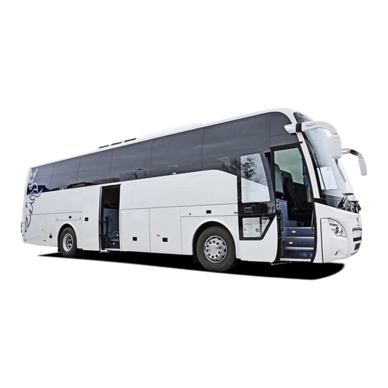
Scania Higer A80, mounted with original SCANIA chassis, is a
newly developed deluxe coach.
The coach mainly runs on the high graded road and highway for
passenger transportation and tourism, etc.
This driver's instruction contains operation, structure, specification
and maintenance of the coach body. You are kindly advised to read the
manuals carefully for the correct operation and maintenance of your
coach.
In regard to the chassis instruction, please read the "Scania
Driver's Instructions" and keep the operating instructions within the
vehicle.
Correct operation and maintenance can result in good
performance and longer service of the coach as well as claim
permission.
This driver's instruction is edited on the basis of the products
before delivery from the factory. Higer Bus Company Limited reserves
the right to modify the specification or change the parts or components
of this model at any time without modification of the delivered coaches.
In case of any questions or suggestions concerning our coaches,
you are welcome to provide feedback for our continuous improvement
of our products as well as better service for you.
To User
HIGER Bus Company Limited
Sep 2012
Advertisement
Table of Contents

Subscribe to Our Youtube Channel
Related Manuals for Scania Higer A80

Summary of Contents for Scania Higer A80
- Page 1 To User Scania Higer A80, mounted with original SCANIA chassis, is a newly developed deluxe coach. The coach mainly runs on the high graded road and highway for passenger transportation and tourism, etc. This driver’s instruction contains operation, structure, specification and maintenance of the coach body.
-
Page 2: Table Of Contents
Catalog Catalog Vehicle Identification ............. 1 Specification ................2 Body Structure ..............4 Driver’s Area ................. 5 Passenger Door ..............6 Rocker Switch ..............11 Driver’s Seat ............... 17 Passenger’s Seat ..............20 Courier Seat ................ 22 Rear View Mirror ..............23 Pneumatic Luggage Compartment ........ - Page 3 Catalog Webasto Water Heater (optional) ........90 Refrigerator (optional) ............96 Toilet (optional) ..............99...
-
Page 4: Vehicle Identification
Vehicle Identification Vehicle Identification Nameplate The coach body nameplate is riveted on the seal panel behind the front passenger door. -
Page 5: Specification
Specification Specification Body ≥ 20 Parking on slope Passenger door Out swing Roof hatch Double glazing front Window windshield, the rest is tempered glass Electrical apparatus 24V negative grounded Roof mounted condenser Type and evaporator A/C system Cooling power Refrigerant R134A Water fountain Optional... - Page 6 Specification Front xenon headlamps Optional Daylight lamp+ LED night lamp Sealed luggage rack Inner Optional Imported skid proof floor equipment leatheroid Composite floor Guardrail ...
-
Page 7: Body Structure
Body Structure Body Structure Front fog lamp Passenger door pump Headlamps Front passenger door Decoration panel Front wheel Windscreen wiper 10 Luggage compartment Windscreen Rear wheel Rear view mirror 12 Middle passenger door... -
Page 8: Driver's Area
Driver’s Area Driver’s Area Driver’s seat Steering wheel Vehicle data recorder Instrument cluster Microphone amplifier Headlamp knob Emergency stop switch Rocker switch(Centre console) Clutch fluid filling port Reverse monitor Rocker switch(L-panel) Vent A/C control panel Retarder control handle Microphone... -
Page 9: Passenger Door
Passenger Door Passenger Door 1 Mechanical Lock The mechanical lock is installed on the outside of front door panel. Unlock the door Rotate the lock cover by 180° to expose the key hole; Insert the key and turn clockwise by 90°; ... - Page 10 Each remote control is coded to ensure its uniqueness. Each new coach is delivered equipped with two remote controls. If they are lost, contact your Scania dealer. If the coach is equipped with only the front passenger door, the...
- Page 11 Passenger Door Note: 1) The remote control will only function when the handbrake is applied or the air pressure in the system is within the normal range. 2) The spare remote control should be kept in a safe location; 3) Do not throw or mishandle the remote controller. 3 Rocker Switch on Dashboard ...
- Page 12 Passenger Door Warning: 1) Ensure that there is no obstacle before operating the passenger door. 2) If the passenger door is obstructed by any person or objects during closing, it will re-open automatically. 4. Emergency Switch Outer emergency switch Proceed as follows to emergency open the door: 1.
- Page 13 Passenger Door Inner emergency switch Proceed as follows to emergency open the door: 1. Turn the rotary control clockwise 2. Open the door Note: The mechanical lock in the door must be unlocked to be able to open the door. Otherwise, the rotary control can’t be turned.
-
Page 14: Rocker Switch
Rocker Switch Rocker Switch Number Icon Name Remark Actuate only when the vehicle has been brought Emergency Stop Switch to a stop. “0” position, marker Headlamp Knob lamps, and headlamps Used only during emergency with the Hazard Warning Signal vehicle in stationary position... - Page 15 Rocker Switch The battery master switch if turned on (by pressing the lower edge) Battery Master Switch will connect to bulk of the electrical system to the battery. 1.Time setting Instrument Cluster 2.Reset Controls Button 3.Decrease 4.Increase Front Fog Lamp Switch Rear Fog Lamp Switch Passenger Door Switch LCD Switch...
- Page 16 Rocker Switch Windshield Electrical Defroster Switch Aisle Light Switch Ceiling Light Switch Driver’s Light Switch Reading Light Switch Night Illumination Light Switch Toilet Master Switch...
- Page 17 Rocker Switch Defroster Fresh Ventilation Switch Luggage Compartment Lamp Switch Switch between air and Horn Shift Switch electric horn. Turn on or off the heating Water Pump Switch system water pump. Rear View Mirror Defrost Switch Switch-1: left side radiator fans Radiator Fan Switch Switch-2:right side...
- Page 18 Rocker Switch High Beam Switch Fuel Heating Switch Check External Check if the external Lighting Switch lightings work well. Control the vehicle cruise Cruise Control Switch at predetermined speed. White Smoke Limiter Switch Allow the wheels to rotate Traction Control Switch at different speed...
- Page 19 Rocker Switch Control the vehicle ECAS Kneeling Switch kneeling and restore vehicle to normal height. ECAS Total Raising / Control the vehicle Total Lowering Switch raising and lowering. Control the vehicle to ECAS Predetermined predetermined height Height / Normal Height and restore vehicle to Switch normal height.
-
Page 20: Driver's Seat
Driver’s Seat Driver’s Seat Operation: (1)Horizontal adjustment Pull lever and move seat forward/backward. Release the lever to lock the seat. (2)Slope adjustment Pull lever and adjust the slope by loading/unloading the front seat cushion area. (3)Seat cushion adjustment Pull lever and move the seat cushion forward/backward. - Page 21 Driver’s Seat (4)Horizontal suspension Lever to the right: Horizontal adjustment released. Lever to the left: Horizontal adjustment locked. (5)Lowering Press switch down: seat lowers. Press switch up: seat moves to the adjusted height set. (6)Damper adjustment By adjusting the damper, the suspension characteristics of the seat can be optimally adapted to every roadway and every driver.
- Page 22 Driver’s Seat (11)Shoulder adjustment Pull lever and adjust the upper backrest area in the desired position. (12)Armrest The inclination can be adjusted by the knurled knob at the front. Note: 1. Please read the operating instructions thoroughly before using your ISRI -seat and acquaint yourself with its technical features.
-
Page 23: Passenger's Seat
Passenger’s Seat Passenger’s Seat 1. Cup holder 3. Footrest 5. Adjusting button 2. Mesh pocket 4. Safety belt 6. Armrest Armrest The armrest can be raised and lowered. A. Raise: lift up the armrest. B. Lower: 1. Lift the armrest upwards. 2. - Page 24 Passenger’s Seat Backrest Pressing button-1 or pulling handle backward to adjust the angle of backrest Transverse movement Pressing the button to move seat in transverse direction.
-
Page 25: Courier Seat
Courier Seat Courier Seat 1 Unfold courier seat Push down both armrests ① and unfold the cushion ② so that the seat is available for use. Caution: The safety belt should not be twisted between the seat cushion and armrest. 2 Fold courier seat ①... -
Page 26: Rear View Mirror
Rear View Mirror Rear View Mirror 1 Outside rear view mirror structure The lower mirror can be turned around and both lower and upper mirrors can be defrosted electrically. 2 Outside rear view mirror adjustment knob Left rear view mirror Right rear view mirror The ignition switch should be turned to “ON”... - Page 27 Rear View Mirror 3 Rear view mirror defroster switch The rear view mirror defrosting switch is powered only when the ignition switch is at the “ON” position. Press the lower edge (with symbol) of the switch, to defrost the rear view mirror and to switch off, press the upper edge.
-
Page 28: Pneumatic Luggage Compartment
Pneumatic Luggage Compartment Pneumatic Luggage Compartment 1 Luggage compartment remote controller Front luggage compartment door, left side Rear luggage compartment door, left side C. Front luggage compartment door, right side D. Rear luggage compartment door, right side Press the button for the luggage compartment door you want to open or close. - Page 29 Pneumatic Luggage Compartment 3 Manual opening of luggage compartment doors To operate the doors manually, you must cut off the air pressure from the doors. This is done with the knobs under the first door on the left-hand side of the vehicle. Right luggage compartment door Left luggage compartment doors Turn the rotary control clockwise to the vertical position for the door(s)
- Page 30 Pneumatic Luggage Compartment 0.6Mpa. If the pressure is too high, please rotate the button anticlockwise until the pressure drop to 0.6Mpa. If the pressure is too low, rotate the button clockwise. Warning: Open the pneumatic luggage compartment door only when the vehicle is parking.
-
Page 31: Passenger Area
Passenger Area Passenger Area Passenger’s area control ① ⑧ai r f l ow regul at or ② ⑦readi ng l i ght s ③ ⑥readi ng l i ght s sw i t ches ④get off ⑤ l oudspeaker Reading light control When the reading lights master switch is turned on, the ③... - Page 32 Passenger Area Get off When the ④ “STOP” button is activated, an alarm and flashing of indicator on the instrument cluster will be initiated to let driver be aware.
-
Page 33: Electronic Clock
Electronic Clock Electronic Clock Production description This type of the clock can display time, temperature and humidity. 1.Real-time display module with 24-hour mode. 2.Used under voltage power DC 24v±5%. 3.Totally nonvolatile with over 8 years of operation in the absence of power. - Page 34 Electronic Clock 9.With distinctive display effect and even brightness. It is suitable to use in the automobile. The main electronic devices are all from aboard. The quality of those devices is good enough. Operation This product uses 24-hour mode. It can display and modify the hour and minute.
- Page 35 Electronic Clock The clock will switch the displaying between date, time, temperature and humidity automatically. During the switching, date will be displayed for 10seconds and time will be for 35 seconds. The temperature and humidity will be displayed for 15 seconds each.
-
Page 36: Microphone Amplifier
Microphone Amplifier Microphone Amplifier Panel instruction 1. POWER: press the button to turn on or turn off the DK-05 microphone amplifier.AS the voltage transformer is integrated into it, the microphone amplifier if turned off, the DVD stops working as well. 2. - Page 37 Safety information Precautions • Use only in a 12-volt DC negative-ground electrical system. • When replacing the fuse, be sure to use one with an identical amperage rating. Using a fuse with a higher amperage rating may cause serious damage to the unit. •...
- Page 38 • Never use solvents such as benzine or alcohol. • This unit cannot play 3-inch (8cm) discs. • Never insert a 3-inch disc contained in the adapter or an irregularly shaped disc. The unit may not be able to eject it. Panel controls Power on/off: Press to turn on/off the unit.
- Page 39 1. Power on/off( press more than 2 seconds) - Mute 2. - To fast search within a track/skip to next or previous track - Radio tune 3. Source switch: Radio, Disc, USB, SD/MMC Card, Aux-in. 4. Radio local/distant 5. Rotate the control to adjust volume level, and press to be flush with the panel.
- Page 40 10. Aux-in 11. USB port 12. Panel open 13. - Short press to select audio menu, and rotate the knob to adjust level. - Long press to enter into setting menu, then each press changes the mode. 14. - Short press to switch to clock display, press again to exit. - Long press to enter clock setting.
- Page 41 1. Zoom (DVD/VCD only) 2. Title (DVD only) 3. Power on/off 4. Setup 5. Menu cursor 6. Enter 7. Program 8. Digit area 9. - Short press to select audio menu, and rotate the knob to adjust level. - Long press to enter into setting menu, then each press changes the mode.
- Page 42 10. Volume 11. Mute 12. - Radio tune - Track skip/seek 13. Subtitle (DVD only) 14. - Radio - Disc (when disc inserted) - Card (when SD/MMC inserted) - USB (when USB inserted) - Aux-in 15. Repeat 16. Repeat A-B 17.
- Page 43 1. Pull out the battery holder while pressing the stopper. 2. Insert the button-type lithium battery with the (+) mark facing upward. Insert the battery holder into the remote control. General operation Switching on and off 1. Press to turn on the unit. 2.
- Page 44 3. Press more than 2 seconds to power off. 4. When you switch off the system or car ignition, the settings, tuner presets and the volume level will be retained in the unit's memory. Clock Display Press DISP on the panel or on the remote control to display clock time, and press DISP again to exit.
- Page 45 BALANCE range: 10 L (full left) to 10 R (full right). L = left speaker, R = right speaker. - FAD Display shows the FADER level. FADER range: 10 R (full rear) to 10 F (full front). R = rear speaker, F = front speaker. Menu Setting Press MENU more than 2 seconds to enter menu mode, then each press changes the mode.
- Page 46 Choose radio distant or local. General Operation DX: Stations with strong and weak signals can be broadcast. LOCAL: Only station with strong signal can be broadcast. - MONO/STEREO Selectable when the current source is Radio mode. This option allows you to select radio FM mono/stereo. - AREA SET This option allows you to select the appropriate frequency spacing for your area.
- Page 47 - Auto Seek Press the buttons to seek the next/previous station automatically. - Manual Seek Press and hold the buttons to enter manual tuning mode. Press the buttons again to move the radio frequency number up or down one step. Note: •...
- Page 48 2. Press a front panel or remote control preset button (numbers 1-6) to select the corresponding stored station. USB/SD/MMC/MP3 Mode 1. Load SD/MMC Card Open the panel and insert the SD/MMC card into the slot. Close the panel, the unit will read the file of the card automatically. 2.
- Page 49 Push SRC button to non-SD mode, press the SD/MMC card to pop out. 3. Load USB Device Insert USB device into the USB jack. The unit will read the file in the USB device automatically. 4. Take out USB Device Press the SRC button to non-USB mode and take out the USB device from the USB jack.
- Page 50 3. Support FAT 16 & FAT 32 4. File name: 32 byte / dir name: 32 byte / tag name: 32 byte. 5. Tag (id3 tag ver 2.0) Title / artist / album: 32 byte support. 6. Multi card reader not support. 7.
- Page 51 Note: • Please confirm whether there is a disc in the unit before you insert another one. • The unit will exit current playing source and enter DVD mode when one disc is inserted. Eject the Disc Press to flip down the panel. Press to eject the disc.
- Page 52 5. For DVD, DVD icon will appear on the display and TITLE appears. Press ENTER or to play. File Type Supported Audio file: MP3 (*.mp3), WMA(*.wma) Video file: XVID MPEG2 (*.vob) MPEG 1 (*.dat) Picture file: JPEG (*.jpg) MP3 file: ISO 9660 or ISO 9660 + Joliet format - Max.30 characters.
- Page 53 to select Press ENTER to confirm. Folder Select to enter folder list and use to select desired folder, press ENTER to confirm. File Select to enter file list and use to select desired file, and press ENTER to play back. For PICTURE, press to slide show the pictures, and press PROG to select picture showing style.
- Page 54 Entering File and Folder Names Names using the code list characters are the only file names and folder names that can be entered and displayed. Using any other character will cause the file and folder names to be displayed incorrectly. The unit recognizes and plays only files with the MP3/WMA extension.
- Page 55 played may not match the order in which they actually played. You may be able to set the order in which MP3/WMA files are to be played by assigning file names beginning with play sequence numbers such as "01" to "99". For example, a medium with the following folder/file hierarchy is subject to Folder Search, File Search or Folder Select as shown below.
- Page 56 playback again. - During the fast forward or backward operation, the volume will be muted. Intro (for CD/VCD Only) You can play the beginning of every track for 15 seconds in sequence. 1. During playback, press INT once. INT ON/OFF will appear on the display. 2.
- Page 57 minutes the unit will turn into standby mode. Repeat A→B Select desired passage to repeat playback. - Press A→B once to select starting point. Display shows REPEAT A. - Press A→B again to select ending point. Display shows REPEAT A→B, and selected passage starts to replay. - Press A→B once again to exit.
- Page 58 select desired track. Press to return to power on logo. Press MENU PBC again to exit menu. Goto Goto desired track/chapter or time point directly. Press GOTO button on the remote control, track or DVD Title/Chapter time display on screen. Current item highlighted.Use...
- Page 59 DVD Audio Select Press AUDIO or R/L to select audio language to listen if the DVD has multiple audio languages. VCD Audio Select Press R/L to select audio channel to listen. DVD Subtitle Select Press SUB.T to select the subtitle language to show if the DVD has multiple language subtitles.
- Page 60 DVD Title Select Press TITLE to display title or chapter list, use cursor or digit number to select, then press ENTER to play. DVD Angle Select Press ANGLE to select different angle to view if the DVD has multiple-angle views. Zoom Press ZOOM button, the picture will be zoomed accordingly.
- Page 61 DVD System Setup to select and ENTER to confirm. - TV SYSTEM: NTSC/PAL 60/PAL/AUTO Select the TV system in the setting menu. - TV TYPE: 4:3PS/4:3LB/16:9 Select TV type to watch wide screen movies. 4:3 Pan Scan: For 4:3 TV, left and right edges will be cut.
- Page 62 - RATING: 1 KID SAFE/2 G/3 PG/4 PG13/5 PG-R/6 R/7 NC-17/8 ADULT The rating of the disc is from 1 to 8: (1) with the most limits when playing. (8) with the least limits when playing. Original setting: 8 Note: The rating can be selected only under the password unlocked status, and the limits can be worked only under the password locked status.
- Page 63 Select one dialogue language that you are familiar with when playing back DVD discs. Note: If the DVD disc has the audio file in the selected language, the dialogues you are listening to will be in the selected language. If the DVD disc does not contain the audio file in the selected language, the dialogues you are listening to will be in the default language.
- Page 64 - BRIGHTNESS Set the brightness of the video output with from 0 to 12. - CONTRAST Set the contrast of the video output with from 0 to 12. - HUE Set the hue of the video output with from -6 to +6. - SATURATION Set the saturation of the video output with from 0 to 12.
- Page 65 1. LCD switch Press the side with mark of the rocker switch and the LCD begins to rotate after being electrified for three seconds. 2. LCD rotate switch Press the side with mark of the rocker switch the LCD unfold, press the other side the LCD fold, and loosening the switch the LCD stop rotating.
-
Page 66: Reverse Monitor
Reverse Monitor Reverse Monitor 1. Safety items The operation power voltage is DC 24V; do not connect to home use electric supply AC 220/110V directly. Keep certain distance as far as possible away from the magnetic objects, such as speaker. Turn off the power first when something or liquid fall into the monitor, ... - Page 67 Reverse Monitor 3) X、Y:No use for this system, because the function is locked. 4) FUNC: Shift between brightness, contrast, color and reset. 5) -: Adjustment down. 6) +: Adjustment up. 7) Reset: When FUNC is set to "reset", press the "-"and"+"buttons at the same time to restore default settings.
-
Page 68: Air Conditioning
Air Conditioning Air Conditioning KONVEKTA General information A/C unit The A/C unit only operates with the engine running. In case of cooling, humidity in the interior part of the vehicle goes down which prevents misting up of windows. The a/c unit works most effectively if windows and doors are closed. - Page 69 Air Conditioning 1 Operation panel (SK-9C)/ function of the keys reheat KVT 商标 Function S1 Temperature setting button L2 Required room temperature button S2 Increase button L3 Outside temperature indicator S3 Decrease button L4 Display S4 Return air, Fresh air button L5 Error indicator S5 Adjust air volume button L6 Cooling indicator...
- Page 70 Air Conditioning controller and the controller will keep the mode and all the settings as the last switch off(The evaporator blowers will run in low speed, when controller switch to power on,). In power on mode, press the power button for 1 second, switch off the power of controller. Mode selection Mode selection: Press the Mode selection button, then can switch to ventilation, cooling, and heating three modes.
- Page 71 Air Conditioning (When the heating indicator flashes, the evaporator blowers run low speed, and can’t adjust manually) Reheat mode In heating mode, when press the increase and decrease button at the same time, switch on reheat function, controller alternating displays FC and actual temperature.
- Page 72 Air Conditioning 5℃≥ desired temp.- room temp. ≥ 3℃ 2 minutes return air, 8 minutes fresh air 3℃≥ desired temp.- room temp. ≥ 0℃ 100% fresh Display evaporator temperature Press increase or decrease button can also display the evaporator temperature. Temperature setting By press temperature setting button, to select the following mode: room temperature, setting temperature, and outside temperature.
- Page 73 Air Conditioning The fault affects the current mode, display will show E code. The fault does not affect the current mode, display will show C code. When temperature is higher than 99 ℃, sensors will be short circuit, and when temperature is lower than -30 ℃, sensors will be circuit.
- Page 74 Air Conditioning 2 Operation panel / function of the keys FUNCTION S1 Adjust air volume button S7 AC(on/off)button S2 Return air/Fresh air/Auto Indicator light AC/AC Button ready/Thawing frost indicator light S3 Decrease button LP/HP error indicator light S4 Increase button Room temperature button S5 Temperature setting button Required room temperature...
- Page 75 Air Conditioning Power-switch Press S6 to turn on the aircondition. Power will be supplied at the same time and the aircondition will work after 5 seconds of delay. For turning off the air condition please press S6 again. The display range of temperature: 0—50 ℃ Temperature settings Normally the temperature display’s the room temperature.
- Page 76 Air Conditioning mode (when compressor is working. L1 lights up with green colour, when compressor is ready for working; L1 blinks with green colour, and when the evaporator is thawing frost; L1 blinks with red colour.) By pressing S7, you switch over to ventilation operating mode and the L1-lamp automatically will turn off.
- Page 77 Air Conditioning and the compressor and fans are getting stopped at the same time. There is 3 seconds delay after every pressure test. b. In case of over and lacking voltage of the power supply, you will get a warning sound, the control unit is blinking and will shut down all power supply at the same time.
-
Page 78: Heating System
Heating System Heating System 1. Brief Introduction The heating system is used to provide a warm comfortable environment for passengers in the bus and provide a good view for the driver in cold weather. By the source of heat, the heating system is classified into two types: independent heating system and dependent system. - Page 79 Heating System 2. Function: Dependent heating system ①Water pump switch ②Temperature adjusting panel Press the marked side of the water pump switch, the heating system starts to work. And then the user could set a temperature to control the operation of the heater, the available range is 5--40℃. When the interior temperature is below 5℃...
- Page 80 Heating System 3. Instruction With the electricity supplied heat control panel will display the interior temperature. Press pump rocker switch, and the heat control panel flicker temperature is the set temperature which is 20℃ original, the interior temperature could be reset after 2 seconds .If the user wants to reset the temperature, press the up/down button until the wanted temperature shows up.
-
Page 81: Defroster
Defroster Defroster Defroster type There are two types of defrosters according to circulation modes. Internal Circulation Defroster In case of ample moisture and easy frosting of front windshield, it directly heat the air in the vehicle to defrost. To initiate the defroster, press the switch lightly for low air speed and further pressing to the second level will lead to the higher defrosting intensity. - Page 82 Defroster ①This rocker switch controls the heated air direction of the defroster. Press the upper side and the heated air will defrost the windscreen while the lower side, will warm the driver’s area. ②This rocker switch controls the circulation mode of the defroster. In low temperature, press the upper side to adopt internal circulation mode and increase the air temperature to deice and defrost.
-
Page 83: Electrical Part
Electrical control unit The ECU of ABS, ECAS lifting system and other electrical control units for chassis and coach body are located in the Scania electric centre in the front of luggage compartment. The electric centre is secured by the red button lock and when not in used, should be secured properly. - Page 84 Electrical Part The fuse box is in a compartment that under the driver’s area. Connecting position...
- Page 85 Electrical Part The ceiling wire harness connects with instruments wire harness in the compartment under the auxiliary dashboard. The chassis wire harness connects with instrument wire harness under the glove compartment near the front door.
-
Page 86: Safety Equipment
Safety Equipment Safety Equipment 1. Safety Belt Tow point safety belt Three point safety belt Function of safety belt Protect the driver and passengers in an emergency. Operation:... - Page 87 Safety Equipment 1) Insert the tongue of the belt into the buckle at the cushion as indicated in the above picture. A click sound will ensure that the tongue is safely “locked” in the buckle. 2) To release, press the RED button at the side of the buckle as shown in the above picture.
- Page 88 Safety Equipment Do not operate the emergency switch other than during an emergency, to avoid any injury. 3. Emergency Exit Window In an emergency, break the side window to escape. As the centre part of the tempered glass window is tougher than the edges, knock the edge, especially from the top middle, by directing the hammer hitting tip at an angle.
- Page 89 Safety Equipment 4. Portable Fire Extinguisher Position: There are two fire extinguishers in the bus, which are under the front row and middle row of the passenger seats. Operation: 1) Pull out the safety pin completely from the handle 2) Press the handle directing nozzle towards the fire, to extinguish the fire.
- Page 90 Safety Equipment 5. Ceiling Hatch ② ① ①Protruding handle ②Red handle Operation: 1. Push the protruding handle upwards to open one side of the roof hatch for ventilation. 2. Pull the protruding handle downwards to close it. 3. In an emergency, pull the red emergency handle downwards on both sides and lift the hatch until it can be opened completely for passengers to escape.
- Page 91 Safety Equipment 6. Using the Correct Amperage Fuse When replacing fuses, it is important not to use over-rated fuses as it may cause overheating and fire.
-
Page 92: Driver Area Radiator (Optional)
Driver Area Radiator Driver Area Radiator (optional) 1. Turn on/off button 2. Increase button 3. Decrease button 4. Temperature display rear. - Page 93 Webasto Water Heater Webasto Water Heater (optional) Water heater operation The heater can be controlled with the switch or timer. Turn the heater system to “heating” and the blower to lower speed (lowest power consumption). Summary Three different kinds of working time can be preset by the timer, only one of which can be activated.
- Page 94 Webasto Water Heater time limit and the heater will work for 15 more minutes. Turn on Manual: Press the button (Continuous heating). Automatic: It starts to work at the ON time preset by the timer. Turn off Manual: Press the button Automatic: It turns off by the OFF time preset by the timer.
- Page 95 Webasto Water Heater until the present time displays instead of the starting time preset. Set the running time Turn off the heater and press the button for three seconds so that the running time is flashing. Set the running time with (10 minutes to 2 hours).
- Page 96 Webasto Water Heater Vehicle with ADR In the vehicle with ADR, the present time and alarm can be set while the ON time cannot be set. The remaining time shows on the display when the heating is working. Failure removal Check the connection of fuse and electrical units in failure.
- Page 97 Webasto Water Heater between each five times’ quick flash shows the failure code. F01 start failure (after trying twice) F02 Flame off (after trying five times) F03 Voltage too high or too low F04 Abnormal flame F05 Abnormal flame before or after combustion F06 Flame detector failure F07 Temperature sensor failure F08 Solenoid valve failure...
- Page 98 Webasto Water Heater by the WEBASTO service men. 5. Run the heater at least ten minutes each month while the engine is cool and the blower is at the lowest speed. Have the heater inspected by the professional before the coming of the cold season. 6.
- Page 99 Refrigerator(optional) Refrigerator (optional) 1)Summarize This machine is compressor refrigeration mode and operates on a low-voltage direct-current power, the recommended refrigerant temperature is -10℃. 2)Operation Instructions Press down “开/ON” the refrigerator start working, and the power light shining. When the cool/protect lamp bright green, the refrigerator works normally;...
- Page 100 Refrigerator(optional) This knob control the temperature of refrigerator, rotate clockwise to rise temperature and counterclockwise to descent it. Note: This machine operates on DC 24V power. Before connecting the power, please select suitable polarity to connect the wire; the red one is positive and the negative one is to be connected with casing;...
- Page 101 Refrigerator(optional) working then automatically restore when voltage resumes to normal status. DC/AC power inverter is used to supply power to compressor. During start-up, if terminal voltage drop is lower than 20V, the start-up failure may occur, with under-voltage warning sound. If this machine is found of abnormal start-up, it is very likely to be ...
- Page 102 Toilet Toilet (optional) Structure Mirror Paper towel holder Soap dispenser Waste paper basket Washbasin Toilet flush button Toilet alarm button Ventilation fan 10 Closestool (inside the cabin)
- Page 103 Toilet Function and operation Master switch The switch is controlled by driver from the instrument cluster. If the toilet cannot work, e.g. toilet system fails, clean water tank is empty and waste tank is full, turn off the switch and lock toilet temporarily. Lighting Two ways control the lighting.
- Page 104 Toilet Indicator light There are two indicator lights for passengers to know whether the toilet is in use. One is engaged on the toilet door and the other one is engaged at the front of the left-hand luggage rack. The green light on or indicator light off indicates it is available while the red light on or indicator light on means it is in use.
- Page 105 Toilet toilet. Hand washing Press the water tap once and the water runs out for three to five seconds. Press the liquid soap button to get the soap. Toilet flush system Push the flush button, the drain valve will open and the waste in the toilet will be flushed into the holding tank.
- Page 106 Toilet floor drain. Clean water tank The tank is used to store clean water for hand washing and toilet flushing, and it consists of the ball valve, the water tank body, the inlet pipe, the outlet pipe, the overflow pipe and the water level warning system.
- Page 107 Toilet Sewage tank Sewage tank is used to store the sewage. It is mainly composed of the tank body, the overflow pipe and the exhaust pipe. When the overflow pipe begins to overflow, it means the tank is full and needs to be drained.
- Page 108 Toilet 4. Please throw the solid waste into waste basket instead of toilet bowl to prevent clogging to the drainage. 5. When cleaning the toilet, do not spray the water on the electrical parts such as electrical units box or fan directly to avoid damaging the wiring.
Need help?
Do you have a question about the Higer A80 and is the answer not in the manual?
Questions and answers