Advertisement
Quick Links
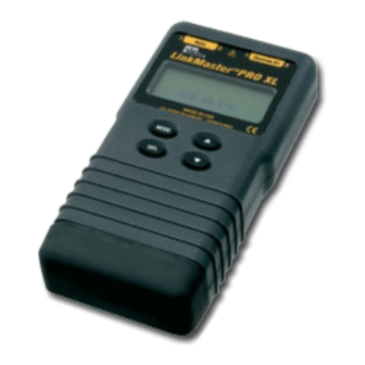
LinkMaster™ PRO XL Tester Instructions
Warning!
Do not attach to energized cables. The LinkMaster
Caution!
Inspect plugs for proper termination before inserting into the LinkMaster
Minimum cable length for testing split pair condition is 3 feet.
LinkMaster
™
Pro XL Key Functions
Power ON by pressing any button
• Main jack for
all testing
Press SEL to:
• Turn on back-light
(Hold 2 seconds)
• Execute current
displayed mode
• Start new test cycle
• Select one of four tones
• Change pair being
measured for length
• Change user selectable options
–Beep On/Off
–Unshielded or Shielded Cable
–Units: Feet or Meters
FEATURES
• Larger back-lighted LCD screen for better test results readability
• Toggle ON/OFF option of lighted display for battery power savings (Hold SEL for 2 seconds)
• Blinks HUBS to assure connected configurations
• Increased voice testing capability detects RJ-11 (1,2 and 3 pair)
• Voice test also shows Normal and Reserve for pins 1 through 6
• Length measurement is shown during initial test results for convenience and time savings
• Eight twisted pair remotes have both RJ-45 and TJ-11 jacks for longer life and increase testing capabilities
• Tone option for pins land 8 for cables connected to hub or switch
• Two line by 16 character full alphanumeric LCD with icons for clear results
• Tests for shield continuity, shorts, opens, miswires, reversals and split pairs with remote connected
• Cable Test – One ended testing for shorts, opens and split pairs (no remote connected)
• Test results displayed in wire map format with message line for shorts and split pairs
• Displays PASS and sounds beep (optional) for T568A/B
• Will display wiremap for 10Base-T and Token Ring with remote connected
• Length measurement in feet or meters using cable capacitance method
• UTP, ScTP and coax length measurements with and without remote attached
• Coax mapping with up to eight color coded coax remotes
™
Pro XL may be damaged.
Arrow Keys
• To change length constant
(see chart for required parameters)
• To change pair or pin selection for tone
• To scroll through setup selectable options
99 Washington Street
Melrose, MA 02176
Fax 781-665-0780
TestEquipmentDepot.com
™
Pro XL.
• Remote jack for patch cords
• Larger back-lighted LCD screen
Six modes of operation
• Cable Test
• Hub Blink
• Length
• Tone
• Coax
• Setup mode
Advertisement

Related Manuals for IDEAL LinkMaster PRO XL


Summary of Contents for IDEAL LinkMaster PRO XL
- Page 1 99 Washington Street Melrose, MA 02176 Fax 781-665-0780 TestEquipmentDepot.com LinkMaster™ PRO XL Tester Instructions Warning! Do not attach to energized cables. The LinkMaster ™ Pro XL may be damaged. Caution! Inspect plugs for proper termination before inserting into the LinkMaster ™...
- Page 2 • Tone generator mode sends four different tones on all conductors, selected pair or selected pin • Auto-off in any mode and low power consumption for long battery life • Low battery symbol indicates when to change battery • Black battery cap allows for quick and easy battery change •...
- Page 3 DESCRIPTION The LinkMaster ™ Pro XL can be powered on by pressing any of the four buttons. LinkMaster ™ Pro XL powers off automatically after 5 minutes of continuous testing of a single cable. Disconnecting the cable restores the tester to normal function. Most power-on modes will timeout in 20 minutes. The tone mode will power off after 2 ⁄...
-
Page 4: Voltage Protection
Tone – The tone mode generates four different tones for use with tone tracers on all pairs, a selected pair or a selected pin. The SEL button selects one of the four tone sounds provided. The up and down arrows scroll through the pairs and pins that have signal on them. The LinkMaster ™... - Page 5 To Test Installed Cable (Horizontal, in-wall cabling) 1) Attach remote(s) to far end of cabling with supplied jumper cable(s). 2) Attach the main unit to patch panel with supplied jumper cable. 3) Press any button to power on. Wiremap results and remote ID number will be displayed, as well as PASS if correctly wired to T568 A/B standards.
-
Page 6: Specifications
3) Connect cable to be traced to main unit. For best signal, do not connect remote. Due to the canceling effect of twisted pairs, the strongest signal is obtained by having one wire of a pair carry tone. Selecting a single pin instead of a pair will do this. 4) To turn tone off, press the MODE button until OFF is displayed, then the SEL button. - Page 7 Miswire – Single or multiple conductors are not connected to the same pins at both ends of the cable. With a remote attached, the wire map shows the pin numbers from display line 1 (main) to display line 2 (remote). A reverse pair is a special case of a miswire in which the pair is wired to the correct pair of pins, but the two conductors are reversed.
Need help?
Do you have a question about the LinkMaster PRO XL and is the answer not in the manual?
Questions and answers