
Related Manuals for Grundfos Conex DIA-G


Summary of Contents for Grundfos Conex DIA-G
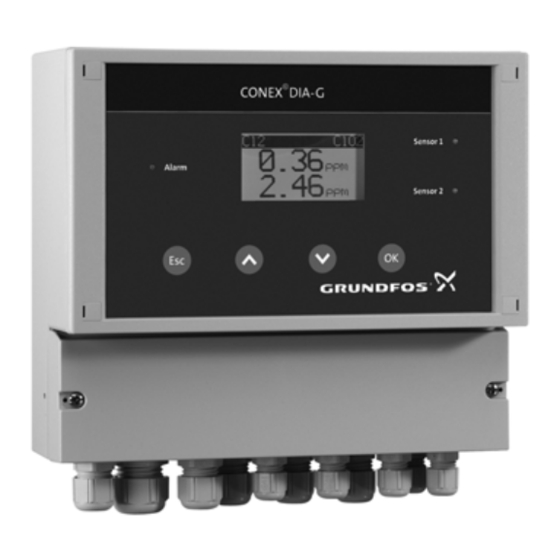
- Page 1 GRUNDFOS INSTRUCTIONS Conex DIA-G ® Gas warning controller Installation and operating instructions...
-
Page 2: Table Of Contents
Warning Obligations of the owner/operations These complete installation and operating manager instructions are also available on Avoidance of danger www.grundfos.com. Identification Prior to installation, read these installation Nameplate and operating instructions. Installation and Type key, gas warning controllers operation must comply with local... -
Page 3: Device Settings
2. Device settings Alarm relay ® Note the key settings for the Conex DIA-G. Fail safe The set values can be stored in the "Setup Note / Factory setting" menu so that you can On (NC) access them again later. Off (NO) Setup Confirmation... - Page 4 Current output Alarm S1 Sensor 1 0-20 mA sec delay 4-20 mA Sensor 2 Others: Assignment Auto. test S2 min. ppm = max. ppm = days testing interval Limit value 1 Current output Sensor 2 0-20 mA 4-20 mA Limit value 2 Others: Assignment min.
-
Page 5: Sensor Types
Should you require further information or should you encounter problems that are not handled in sufficient depth in this manual, please contact Grundfos Water Treatment. We shall be pleased to support you with our comprehensive know-how in the fields of measuring and control technology as well as water treatment. -
Page 6: Safety
5. Safety 5.3 Avoidance of danger This manual contains general instructions that must Warning be observed during installation, operation and Do not use the device for monitoring maintenance. This manual must therefore be read by constant concentrations. The device is the installation engineer and the relevant qualified designed for detecting leaks. -
Page 7: Identification
Pos. Description Type designation DIA-G, 1-D/A/HC 2-D/A/HC, W-J Model 308-2000-10012 S/N: 08/11221 Product Conex DIA-G Voltage [V] 110-240V 50/60Hz 24V/DC, 30 VA, IP 65 Frequency [Hz] 96732266P1108060808565 Product number Country of origin Year and week of production Marks of approval, CE mark, etc. -
Page 8: Type Key, Gas Warning Systems, Prepacked (With Sensors And Sensor Equipment)
6.3 Type key, gas warning systems, prepacked (with sensors and sensor equipment) Example: DIA-G-P, CLP-OP-B, W-J Example: DIA-G CLP- OP- B. ® Conex gas warning system DIA-G Dosing Instrumentation Advanced with gas detection Prepacked Sensor 1 Chlorine gas/chlorine dioxide gas, amperometric measurement Ozone gas, amperometric measurement Chlorine gas, potentiostatic measurement Chlorine dioxide gas, potentiostatic measurement... -
Page 9: Product Description And Accessories
7. Product description and 7.1 General description accessories ® The Conex DIA-G is a gas warning controller for monitoring gas concentrations, for example in This universal device offers high-precision storage or dosing rooms. With a maximum of two measuring of chlorine, chlorine dioxide, ozone, independently connected sensors, the gas ammonia or hydrochloric acid. - Page 10 Conex DIA-G Sensor 1 Alarm Sensor 2 Fig. 2 Gas warning system Pos. Description Amperometric gas sensor ® Potentiostatic gas sensor with Conex DIA-G sensor interface Gas container Gas dosing unit ® Conex DIA-G gas warning controller Horn Flashing warning system...
-
Page 11: Dimensional Sketches
7.2 Dimensional sketches Ø 4.5 ® Fig. 3 Conex DIA-G 101.5 ® Fig. 4 Conex DIA-G sensor interface... -
Page 12: Technical Data
8. Technical data Observe the permissible temperature range of the sensors! Caution Note Observe the accuracy of the sensor! Electronics 16-bit microprocessor technology Display Backlit plain-text display Display languages German, English, French, Spanish, Russian and Polish Indication mode In ppm for measured values of both sensors ®... -
Page 13: Signal Inputs And Outputs
8.1 Signal inputs and outputs Five potential-free relay outputs, switchable to NO (normally open) or NC (normally closed) (fail safe); maximum 250 V / 6 A, maximum 550 VA ohmic load: Relay outputs • two relays for the limit values of each of the two sensors •... -
Page 14: Measuring And Setting Ranges
8.4 Measuring and setting ranges 8.4.1 Measuring parameter and working range for amperometric sensors Measuring parameter Measuring range Accuracy Temperature range Product number [ppm] [°C] 91835237 , ClO 0.00 - 5.00 ± 10 +5 to +45 (314-011) 96687714 0.00 - 5.00 ±... -
Page 15: Caution
Risk of malfunction or damage to the Gas sensors should not be mounted close ® Conex DIA-G! Grundfos accepts no to major sources of interference such as Caution liability for damage caused by incorrect Caution large machines, etc. -
Page 16: Installation Of The Conex ® Dia-G
DIA-G Enclosure class IP65 is only guaranteed if the terminal cover is correctly sealed! Caution Do not damage the terminal cover gasket! The terminal cover gasket must fit exactly! Conex DIA-G Sensor 1 Alarm Sensor 2 Fig. 6 Mounting drawing... -
Page 17: Assembling The Conex ® Dia-G Sensor Interface
® 10. Commissioning/electrical 9.7 Assembling the Conex DIA-G sensor interface connections If potentiostatic sensors are used, a separate ® Warning Conex DIA-G sensor interface must be installed. Switch off the power supply before Warning installing! Switch off the power supply before Enclosure class IP65 is only guaranteed installing! with the front panel of the terminals... -
Page 18: Conex ® Dia-G Terminal Assignment
® 10.1 Conex DIA-G terminal assignment Input Sensor 1 Sensor 2 Sensor 1 Sensor Interface Main in Alarm 24 V Reset – – – N PE N PE – – – – – 24V Out Sensor 2 Sensor Interface ® Fig. -
Page 19: Power Supply Connection
Assignment Terminal Description Bat ok Battery backup: working Analog output sensor 1 Screen Analog output sensor 25 Screen Sensor 1 Connection for amperometric sensor 1 Screen Sensor 2 Connection for amperometric sensor 2 Screen Selection switch for sensor interface termination resistor Position 1: On Position 0: Off... -
Page 20: Connecting A Backup Battery
10.3 Connecting a backup battery 10.5 Current output Voltage supply via backup battery: Ensure correct polarity! Maximum load: Caution • Connect + to terminal 19. 500 Ω. • Connect - to terminal 20. The current output can be set to one of the two Backup battery monitoring function: standard ranges "0-20 mA"... -
Page 21: Terminal Assignment For Conex ® Dia-G
® 10.6 Terminal assignment for DIA-G sensor interface Conex 6 5 4 ADDR 24 V DC ® Fig. 10 Conex DIA-G sensor interface terminal ® Key for Conex DIA-G sensor interface terminal diagram Assignment Terminal Description CAN connection to DIA-G (sensor) CAN connection to DIA-G (sensor) Screen connection (CAN) Screen... -
Page 22: Connection Of Sensors
Sensor 1 screen brown white Sensor 2 screen brown The wire colours refer to Grundfos cable. Sensor 1: • Connect the brown wire (+) to terminal 49. • Connect the white wire (-) to terminal 45. • Connect the screen to terminal 47. - Page 23 10.7.2 Potentiostatic sensors The sensor is plugged directly into the interface. The interface is connected to the gas warning controller using a 4-wire cable with single screening (special cable for CAN connections). Maximum length ® (maximum distance between Conex DIA-G sensor interface and gas warning controller): 500 metres.
- Page 24 The sensor interface address is specified on the Green round selection switch for the CAN address (S2 ADDR) as follows: The wire colours refer to the Grundfos cable. – Sensor interface 1: address 1 – Sensor interface 2: address 2 •...
-
Page 25: Operation
11. Operation • If you are using amperometric sensors, select the "New sensor" menu in the sensor menu. This indicates to the device that a new sensor is being 11.1 Initial start-up used. The installation and replacement data in the "Sensor data" service menu are updated The sensor must be replaced after a gas automatically. -
Page 26: Control And Display Elements
11.2 Control and display elements 11.3 Operating modes • Display mode: This is the standard operating mode. The device automatically starts up in this operating mode. In this operating mode it is possible to: – read current measured values – read error messages –... -
Page 27: Operating Instructions
Once the language selection has been confirmed 11.5.3 Display using [OK], the measured value for the measured Apart from in the display level, the display variable "Chlorine" appears on initial start-up. Note is generally in 5-line format. On subsequent start-ups, the last selected measured variable appears in the display. -
Page 28: Software Overview
11.6 Software overview 11.6.1 "Setup" menu Main menu > Setup Submenu 1 Submenu 2 Submenu 3 Submenu 4 German English Spanish Language French Russian Polish Chlorine 314-011 Chlorine 314-021 314-041 Sensor 1 314-011 Ozone 314-071 Ozone 314-013 HCl 314-061 314-031 Chlorine 314-011 Chlorine 314-021 314-041... - Page 29 Main menu > Setup Submenu 1 Submenu 2 Submenu 3 Submenu 4 On (N.C.) Fail safe Off (N.O.) Confirmation Limit value 1 (S1) Sensor 1 Limit value 2 (S1) Alarm relay Test sensor Limit value 1 (S2) Sensor 2 Limit value 2 (S2) Test sensor Battery backup N.O.
-
Page 30: Min. Ppm = Ma Max. Ppm = Ma
Main menu > Setup Submenu 1 Submenu 2 Submenu 3 Submenu 4 0-20 mA 4-20 mA Sensor 1 Min. ppm = mA Others (S1) Max. ppm = mA Current output 0-20 mA 4-20 mA Sensor 2 Min. ppm = mA Others (S2) Max. - Page 31 11.6.3 "Service" menu Main menu > Service Submenu 1 Submenu 2 Submenu 3 List of events Measured value Aut. test Sensor 1 Sensor data Limit values Settings (S1) Alarm relay List of events Measured value Aut. test Sensor 2 Sensor data Limit values Settings (S2) Alarm relay...
- Page 32 11.6.4 "Fine adjustment" menu Main menu > Fine adjustment Submenu 1 Submenu 2 Submenu 3 Submenu 4 xx.xx ppm Change xxx.x nA Manual zero pt. (S1) Delete xx.xx ppm Measured value (S1) Cell xxxx.x nA Sensor 1 Calibration xx.xx nA/ppm Result (S1) Slope xx nA/ppm...
-
Page 33: Main Menu
11.7 Main menu 11.8 Setup • From display mode, press [OK] or from the submenus, press [Esc] the relevant number of Main menu > Setup times to access the main menu. Submenu 1 Selection options in the main menu • "Sensor 1 / Sensor 2": parameterisation of Language sensors. -
Page 34: Sensor
11.8.2 Defining sensor 1 11.8.4 Setting the function of the limit value relay for the sensors Main menu > Setup Main menu > Setup Submenu 1 Submenu 2 Submenu 1 Submenu 2 Submenu 3 On (N.C.) Chlorine 314-011 Fail safe Off (N.O.) Chlorine 314-021 Limit relay... - Page 35 11.8.5 Assigning and setting the alarm relay Main menu > Setup Submenu 1 Submenu 2 Submenu 3 Submenu 4 On (N.C.) Fail safe Off (N.O.) Confirmation Limit value 1 (S1) Sensor 1 Limit value 2 (S1) Alarm relay Test sensor Limit value 1 (S2) Sensor 2 Limit value 2 (S2)
- Page 36 In case of a power supply failure, the Conex DIA-G can be supplied with 24 VDC using an external backup battery (UPS), for example Grundfos backup battery, order no. 96725709 (336-308). A contact from an integrated standby display on the battery backup to an electrically isolated input on the ®...
- Page 37 11.8.8 Code function Reset function Codes (a numerical value between 1 and 9999) can Entering code "1998" deletes all previously activated be used to protect the device from unauthorised codes. All previous access codes are deleted and access. reset to "Code: 0000". ®...
- Page 38 11.8.11 Factory setting reset 11.8.13 Setting the CAN Interface ® In the "Factory setting" submenu, the Conex DIA-G In the "CAN interface" submenu, the external CAN can also be reset to the factory setting using code interface (if connected) is activated or deactivated, 6742.
-
Page 39: Parameterising The Sensors
11.9 Parameterising the sensors In the "Sensor 1 or 2" menu, the sensors are The sensor menus are only displayed parameterised, for example setting of limit values Note when the sensor is selected (in the "Setup" and alarms or carrying out sensor tests. menu). -
Page 40: Off On
11.9.2 Setting limit values for the sensors Main menu > Sensor 1 (Sensor 2) Submenu 1 Submenu 2 Submenu 3 Submenu 4 Submenu 5 Limit value 1 x.xx ppm Limit value Limit value 2 x.xx ppm xxx sec delay Hysteresis x.xx ppm hysteresis The menu structure for sensor 1 and sensor 2 is Setting the switching hysteresis... - Page 41 11.9.3 Setting the alarm delay 11.9.4 Replacing/changing a sensor Message: Change sensor Main menu > Sensor 1 (Sensor 2) Faulty sensors must be replaced! The potentiostatic sensor or the sensor disc of Submenu 1 Submenu 2 the amperometric sensor must be replaced Alarm delay xxx sec delay in the following cases:...
- Page 42 Measuring Maximum storage Expected life Sensor type Product number parameter time (months) (months) , ClO 91835237 (314-011) Amperometric sensor (disc) 96687714 (314-013) Potentiostatic sensors For every sensor is noted the manufacturing date as The "Change sensor" message is displayed for well as the maximum storage time and the expected potentiostatic sensors: life.
-
Page 43: Requesting Settings In The Service Menu
11.10 Requesting settings in the service menu Main menu > Service Submenu 1 Submenu 2 Submenu 3 List of events Measured value Aut. test Sensor 1 Sensor data Limit values Settings (S1) Alarm relay List of events Measured value Aut. test Sensor 2 Sensor data Limit values... -
Page 44: Limit Value
Measured value: Display example of measured Settings: The settings for limit values and the alarm value, Sensor 1. relay are displayed here so that the values can be checked without accessing the relevant menus in the "Setup" menu. Sensor 1 Display examples: xx.xx ppm Limit values... -
Page 45: Fine Adjustment Menu
Test relay (check operation of the relays) – If the connected warning or safety equipment is not activated: Check the connected warning or All warning and safety equipment safety equipment and cabling. Repair if connected to the limit value and alarm necessary. - Page 46 11.11.1 Manually setting the zero point for the ® The Conex DIA-G is a gas detector. It is sensors Note not suitable for continuous measuring of a gas concentration or for MAC monitoring. Warning If this function is used incorrectly, there is In the "Sensor 1"/"Sensor 2"...
-
Page 47: Actions During Operation
11.11.4 Damping the measured value display Alarm messages The mean value generation of the display (and A sensor-specific alarm refers to the sensor that is therefore also of the current output) can be modified flashing in the header. Alarms that do not relate to in order to dampen a frequently changing measuring sensors are displayed in the bottom row. - Page 48 Display option for no sensors No sensor Icon 1 Icon 2 Icon 3 Icon 4 Special display if no sensor is set in the "Setup" menu. Reading measured values Icon Display Description In display mode, the current measured values can For configured alarm relay always be read.
-
Page 49: Limit Value 1
11.12.3 Exceeding limit values Confirmation of limit value 2 If Limit value 1 is exceeded for a sensor: The relay for limit value 2 usually remains activated until the measured value has dropped below limit • The LED of the relevant sensor flashes. value 2. -
Page 50: Error Messages And Fault Finding
12. Error messages and fault finding In case of measurement faults, see the Note manual of the gas sensors. 12.1 Error messages Error message Cause Remedy Sensor test Manual/automatic sensor test Check the sensor and the connecting line. error. failed. Replace the sensor. -
Page 51: Fault Finding
12.2 Fault finding Fault Cause Remedy No display No power supply. Connect the power supply. following start-up. Display contrast too light/too dark. Set the contrast in the "Setup" menu. See section 11.8.9 Setting the display contrast. Display Open circuit in cable between Check the connecting cable, and permanently at sensor and gas warning device. -
Page 52: Maintenance
This product or parts of it must be disposed of in an environmentally sound way. Use appropriate waste collection services. If this is not possible, contact the nearest Grundfos company or service workshop. The 2006/66/EC guideline requires users to return all used and worn-out batteries and accumulators. They... - Page 53 Declaration of conformity GB: EU declaration of conformity DE: EU-Konformitätserklärung We, Grundfos, declare under our sole responsibility that the products Wir, Grundfos, erklären in alleiniger Verantwortung, dass die Conex® DIA-G, DIS-G, DIS-D, DIS-PR, to which the declaration below Produkte Conex® DIA-G, DIS-G, DIS-D, DIS-PR, auf die sich diese relates, are in conformity with the Council Directives listed below on Erklärung beziehen, mit den folgenden Richtlinien des Rates zur...
- Page 54 Argentina China Germany Bombas GRUNDFOS de Argentina S.A. Grundfos Alldos GRUNDFOS Water Treatment GmbH Ruta Panamericana km. 37.500 Centro Dosing & Disinfection Reetzstraße 85 Industrial Garin ALLDOS (Shanghai) Water Technology D-76327 Pfinztal (Söllingen) 1619 - Garin Pcia. de B.A. Co. Ltd.
- Page 55 Phone: +40 21 200 4100 Telefax: +66-2-725 8998 Phone: +82-2-5317 600 Telefax: +40 21 200 4101 Turkey Telefax: +82-2-5633 725 E-mail: romania@grundfos.ro GRUNDFOS POMPA San. ve Tic. Ltd. Latvia Russia Sti. SIA GRUNDFOS Pumps Latvia ООО Грундфос Россия Gebze Organize Sanayi Bölgesi Deglava biznesa centrs ул.
- Page 56 96709884 0419 ECM: 1260226 www.grundfos.com...
Need help?
Do you have a question about the Conex DIA-G and is the answer not in the manual?
Questions and answers