Table of Contents
Advertisement
Advertisement
Table of Contents

Subscribe to Our Youtube Channel
Related Manuals for SOYO Motherboard SY-6BA+ IV


Summary of Contents for SOYO Motherboard SY-6BA+ IV
- Page 1 SY-6BA+ IV Motherboard **************************************************** ® ® Pentium III, Pentium II & Celeron Processor supported 82440 BX AGP/PCI Motherboard 66 & 100 MHz Front Side Bus supported ATX Form Factor **************************************************** User's Manual...
- Page 2 It is the policy of Soyo Computer Inc. to respect the valid patent rights of third parties and not to infringe upon or to cause others to infringe upon such rights.
-
Page 3: Table Of Contents
Table of Contents CHAPTER 1 MOTHERBOARD DESCRIPTION ...1 INTRODUCTION ...1 KEY FEATURES ...1 HANDLING THE MOTHERBOARD ...5 ELECTROSTATIC DISCHARGE PRECAUTIONS ...5 SY-6BA+ IV MOTHERBOARD LAYOUT ...6 SY-6BA+ IV MOTHERBOARD COMPONENTS ...7 MICROPROCESSOR...9 MEMORY...9 CHIPSET ...11 1-10 I/O INTERFACE CONTROLLER ...16 1-11 HARDWARE MONITOR...18 1-12... - Page 4 Table of Contents SOYO COMBO SETUP ...54 STANDARD CMOS SETUP ...61 BIOS FEATURES SETUP...64 CHIPSET FEATURES SETUP ...69 POWER MANAGEMENT SETUP...72 PNP/PCI CONFIGURATION SETUP...76 LOAD SETUP DEFAULTS...79 INTEGRATED PERIPHERALS ...80 SUPERVISOR PASSWORD...85 3-10 USER PASSWORD...86 3-11 IDE HDD AUTO DETECTION...87 CHAPTER 4 DRIVERS INSTALLATION ...88...
-
Page 5: Chapter 1 Motherboard Description
The SY-6BA+ IV provides the user with a very complete and convenient CPU setting environment. The CPU settings are all adjusted through the special SOYO COMBO page in the BIOS, therefore rendering the use of jumpers obsolete. CPU FSB Frequency... - Page 6 Motherboard Description CPU Multiplier The SY-6BA+ IV supports a wide range of multipliers: 2.0x, 2.5x, 3.0x, 3.5x, 4.0x, 4.5x, 5.0x, 5.5x, 6.0x, 6.5x, 7.0x, 7.5x and 8.0x CPU Core Voltage The CPU Core voltage is set automatically according to CPU needs. The SY-6BA+ IV supports an advanced Core voltage feature;...
- Page 7 Motherboard Description capable of transferring data up to 66 Mbytes/sec (IDE DMA Mode 4). Wake-On-LAN Supports Wake-On-LAN (Some advanced network cards can wake the system up over the network, the WOL connector is provided by the SY-6BA+ IV to support this function). Multiple boot The SY-6BA+ IV supports booting from devices such as CD-ROM.
- Page 8 SY-6BA+ IV, a motherboard to trust. Year 2000 compliant PC98 compliant FCC/CE complaint Ø USER FRIENDLY SOYO Combo Setup Jumperless design You can set up the following options trough the BIOS setting CPU FSB frequency CPU multiplier CPU Vcore voltage PCI clock...
-
Page 9: Handling The Motherboard
Motherboard Description HANDLING THE MOTHERBOARD To avoid damage to your M otherboard, follow these simple rules while unpacking: Ø Before handling the M otherboard, ground yourself by grasping an unpainted portion of the system's metal chassis. Ø Remove the M otherboard from its anti - static packaging. Hold the Motherboard by the edges and avoid touching its components. -
Page 10: Sy-6Ba+ Iv Motherboard Layout
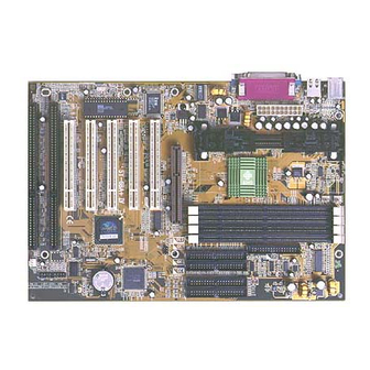
Motherboard Description 1-5 SY-6BA+ IV MOTHERBOARD LAYOUT PS/2 KB PS/2 Mouse Connector Connector USB 1 USB 2 COM 1 COM 2 ITE 8671 I/O Chipset JP44 Header Winbond W83782M 828AC Hardware Monitoring Back Panel JP10 PWRFAN Slot 1 ® CPUFAN ®... -
Page 11: Sy-6Ba+ Iv Motherboard Components
Motherboard Description 1-6 SY-6BA+ IV MOTHERBOARD COMPONENTS 828AC ® ® SY-6BA+ IV ®... - Page 12 Motherboard Description ATX Power Supply Connector Slot 1 Connector Power On by Keyboard Jumper CPU multiplier release Jumper Intel 82440 BX PCI/ AGP Set CPU Cooling Fan Connector Power Cooling Fan Connector DIMM Bank 5 V Stand- by indicator LED Floppy Disk Drive (FDD) Port Bus M astering E - IDE / A TAPI Ports 32- bit AGP Slot...
-
Page 13: Microprocessor
Motherboard Description SY-6BA+ IV 1-7 MICROPROCESSOR The motherboard supports a single Slot 1 processor. The processor’s VID pins automatically program the voltage regulator on the motherboard to the required processor voltage. In addition, the front side bus speed (66 MHz and 100 MHz) is automatically selected. The motherboard supports all current Slot 1 processor speeds, voltages, and bus frequencies. - Page 14 Motherboard Description t wo, three, or four sockets. Using the serial presence detect (SPD) data structure, programmed into an E²PROM on the DIMM, the BIOS can determine the SDRAM’s size and speed. M inimum DIMM memory size is 8 MB; maximum DIMM memory size is 256 MB. M emory size and speed can vary bet ween sockets.
-
Page 15: Chipset
Motherboard Description 1-8.3 ECC Memory ECC memory detects multiple- bit errors and corrects single- bit errors. When ECC memory is installed, the BIOS supports both ECC and non- ECC mode. ECC mode is enabled in the Setup program. The BIOS automatically detects if ECC memory is installed and provides the Setup option for selecting ECC mode. - Page 16 Motherboard Description A. G.P. interface Ø Complies with the A . G.P. specification Ø Support for +3.3 V A . G.P.- 66/ devices Ø Synchronous coupling to the host- bus frequency PCI bus interface Ø Complies with the PCI specification Ø...
- Page 17 Motherboard Description Ø Complies with the PCI specification Ø Full ISA bus support USB controller Ø Two USB ports Ø Support for legacy keyboard and mouse Ø Support for UHCI interface Integrated dual - channel enhanced IDE interface Ø Support for up to four IDE devices Ø...
- Page 18 Motherboard Description Specifications, Rev 2.1, is independent of the PCI bus and is intended for exclusive use with graphical display devices. A . G.P. overcomes certain limitations of the PCI bus related to handling a large amount of graphics data with the following features: Pipelined memory read and write operations that hide memory access latency Demultiplexing of address and data on the bus for near 100 percent...
-
Page 19: Ide Support
Motherboard Description SY-6BA+ IV 1-9.5 IDE Support The motherboard has two independent ATA 33 and two independent ATA 66 bus-mastering PCI IDE interfaces. These interfaces support PIO Mode3, PIO Mode 4, ATAPI devices (e.g., CD-ROM), and Ultra DMA/33 (IDE1, IDE2) or Ultra DMA/66 (IDE3, IDE4) synchronous-DMA mode transfers. See “IDE Device installation”... -
Page 20: I/O Interface Controller
Motherboard Description recognize it as both the A and B drive 1-9.6 Real-Time Clock, CMOS SRAM, and Battery The real - time clock is compatible with DS1287 and MC146818 components. The clock provides a time- of- day clock and a multicentury calendar with alarm features and century rollover. -
Page 21: Keyboard And Mouse Interface
Motherboard Description Bi- directional (PS/ 2 compatible) Bi- directional EPP. A driver from the peripheral manufacturer is required for operation. Bi- directional high- speed ECP 1-10.3 Diskette Drive Controller The I / O controller is soft ware compatible with the 82077 diskette drive controller and supports both PC - A T and PS/ 2 modes. -
Page 22: Hardware Monitor
Motherboard Description 1-11 HARDWARE MONITOR The optional hardware monitor subsystem provides low - cost instrumentation capabilities. The features of the hardware monitor subsystem include: Ø An integrated ambient temperature sensor Ø Fan speed sensors, which monitor the fan 1 and fan 2 connectors Ø... -
Page 23: Chapter 2 Hardware Installation
Hardware Installation HARDWARE INSTALLATION Congratulations on your purchase of SY-6BA+ IV M otherboard. Y ou are about to install and connect your new M otherboard. Note: Do not unpack the M otherboard from its protective anti - static packaging until you have made the following preparations. 2-1 PREPARATIONS Gather and prepare all the following hardware equipment to complete the installation successfully:... -
Page 24: Unpacking The Motherboard
The SY - 6BA + IV 82440 BX AGP/ PCI Motherboard The Quick Start Guide The Installation CD - ROM SOYO 3- in- 1 Bonus Pack CD - ROM (Norton AntIVirus, Ghost and V irtual Drive) The CPU Retention Set One IDE Device A TA 66 Flat Cable... -
Page 25: Installation Guide
Hardware Installation 2-3 INSTALLATION GUIDE W e will now begin the installation of the M otherboard. Please follow the step- by - step procedure designed to lead you to a complete and correct installation. Warning: T urn off the power to the M otherboard, system chassis, and peripheral devices before performing any work on the M otherboard or system. -
Page 26: 2-3.1 Cpu Fan Installation
Hardware Installation 2-3.1 CPU Installation Y our SY - 6BA + IV motherboard comes with a CPU retention set kit. The retention set is used to hold the processor attached to the Slot 1 CPU connector on the motherboard. Mark your CPU Frequency: your CPU that should be clearly marked on the CPU cover. - Page 27 Hardware Installation Open the two sides by folding them up. Push the locks on top of the CPU inward. SY-6BA+ IV...
- Page 28 Hardware Installation Insert the CPU into the retention module. The CPU fits in the CPU slot in only ONE way, do not try to force it in. After completely inserting the CPU, push the two locks on top of the CPU outward.
- Page 29 Hardware Installation Note: Installing a heat sink and cooling fan on top of your CPU is necessary for proper heat dissipation. Failing to install these items may result in overheating and possible burn-out of your CPU. 2-3.1.1 CPU Fan Installation Y our Slot 1 processor kit comes with a cooling fan.
-
Page 30: 2-3.2 Sdram Memory Module Installation
Hardware Installation SY-6BA+ IV 2-3.2 SDRAM Memory Module Installation ® ® ® Y our board comes with four DIMM sockets, providing support for up to 512 M bytes or 1GB (with registered DIMMs). For 66 MHz front side bus CPUs use 12ns or faster memory; for 100 MHz front side bus CPUs use 8ns (100 MHz, PC100 compliant) memory. - Page 31 Hardware Installation Number of Memory Modules RAM Type Memory Module Size (MB) Note: (1) 256 MB memory modules available on PC registered DIMM only. (2) Always install memory modules in the order prescribed in this table. (3) Do not install unbuffered and registered memory modules together. Important: It is of prime importance that you install DIMM modules as outlined in the table above in order to preserve signal integrity on 100 MHz front side bus systems.
-
Page 32: 2-3.3 Motherboard Connector
Hardware Installation 2-3.3 Motherboard Connector 2-3.3.1 IDE Device Installation (HDD, CD-ROM) The 6BA + IV comes with four IDE connectors, with support for up to 8 IDE Devices. For the supported interface modes, refer to the table below: PIO mode Connector IDE 1 &... - Page 33 Hardware Installation SY-6BA+ IV 80-Conductor ATA 66 Flat Cable 40-pin...
-
Page 34: Floppy Drive Installation
Hardware Installation SY-6BA+ IV 2-3.3.2 Floppy Drive Installation ® ® Pin -1 Floppy Drive Connector ® 828A The system supports 5 possible floppy drive types: 720 KB, 1.2 MB, 1.44 MB, 2.88 MB, and LS- 120. In addition, this M otherboard supports a 3- mode (720KB / 1.2 MB/ 1.44 MB) floppy commonly used in Japan. - Page 35 Hardware Installation 2-3.3.3 Front Panel Connections ® ® 828A Plug the computer case's front panel devices to the corresponding headers on the Motherboard. 1. Power LED & KeyLock Plug the Power LED cable into the 5-pin Keylock header. Some systems may feature a KeyLock function with a front panel switch for enabling or disabling the keyboard.
- Page 36 Hardware Installation SY-6BA+ IV 2. Reset Plug the Reset push-button cable into the 2-pin Reset header on the Motherboard. Pushing the Reset button on the front panel will cause the system to restart the boot-up sequence. Reset Pin Assignment Power Good 3.
- Page 37 Hardware Installation SY-6BA+ IV 5. IDE LED Attach the 2-pin IDE device LED cable to the corresponding IDE LED header on the Motherboard. This will cause the LED to lighten when an IDE (HDD, CD-ROM) device is active. HDD LED Pin Assignment LED Anode LED Cathode 6.
- Page 38 Hardware Installation 2-3.3.4 Back Panel Connections All external devices such as the PS/2 keyboard, PS/2 mouse, printer, modem, USB can be plugged directly onto the Motherboard back panel. Only after you have fixed and locked the Motherboard to the computer case can you start connecting the external peripheral devices.
- Page 39 Hardware Installation 1. Onboard Serial Ports COM1/COM2 External peripherals that use serial transmission scheme include: serial mouse, and modem. Plug the serial device cables directly into the COM1/COM2 9-pin male connectors located at the rear panel of the Motherboard. 2. Parallel Port PRT This parallel port is used to connect the printer or other parallel devices.
- Page 40 Hardware Installation 5. Universal Serial Bus USB1/USB2 This Motherboard provides two USB ports for your additional devices. Plug the USB device jack into the available USB connector USB1 or USB2. Standard device drivers come with the Win98 for commonly used USB devices.
-
Page 41: Wake-On-Lan (Wol)
Hardware Installation 2-3.3.5 Other Connections 1. Wake-On-LAN (WOL) Attach the 3-pin connector from the LAN card which supports the Wake- On-LAN (WOL) function to the JP44 header on the Motherboard. This WOL function lets users wake up the connected computer through the LAN card. - Page 42 Hardware Installation SY-6BA+ IV 2. Infrared (IR1) Plug the 5-pin infrared device cable to the IR1 header. This will enable the infrared transfer function. This Motherboard meets both the ASKIR and HPSIR specifications. Please install according to the following pin assignment: Serial Infrared (IR1) Connector IR1 Pin Assignment 1 2 3 4 5...
- Page 43 Hardware Installation 4. Cooling Fan Installation (1) CPU Cooling Fan After you have seated the CPU properly on the processor, attach the 3-pin fan cable to the CPUFAN connector on the Motherboard. The fan will stop when the system enters into Suspend Mode. (Suspend mode can be enabled from the BIOS Setup Utility, [POWER MANAGEMENT] menu.) To avoid damage to the system, install according to the following pin assignment:...
- Page 44 Hardware Installation (2) Chassis Cooling Fan Some chassis also feature a cooling fan. This Motherboard features a CHAFAN connector to provide 12V power to the chassis fan. Connect the cable from the chassis fan to the CHAFAN 3-pin connector. Install according to the following pin assignment: Chassis Cooling Fan CHAFAN Pin Assignment...
- Page 45 Hardware Installation 2-3.3.6 AGP VGA Card Insert the AGP VGA card into the AGP slot. Then connect the monitor information cable to the AGP card back plane external connector. Follow the manufacturer's instructions to perform the AGP VGA drivers installation. Other Display Cards: Insert other types of VGA cards into the PCI or ISA expansion slots according to card specifications.
-
Page 46: Atx Power
Hardware Installation 2-3.3.8 ATX Power Supply Plug the connector from the power directly into the 20-pin male ATX PW connector on the Motherboard, as shown in the following figure. ATX Power Warning: Follow these precautions to preserve your Motherboard from any remnant currents when connecting to power supply: Turn off the power supply and unplug the power cord of the power supply before connecting to PW connector. -
Page 47: Jumper Setting
Hardware Installation This motherboard requires a power supply, that meets the ATX 2.03 specifications. Make sure the power supply can support at least 720mA on the 5V Standby lead. Please install the ATX power according to the following pin assignment: ATX Power 5VSB PW-OK... - Page 48 BIOS may allow the user to set a higher multiplier value. Doing so will however force your CPU to operate out of its specifications, and therefore SOYO can not guarantee the proper functioning of your system. Refer to the following table:...
-
Page 49: 2-3.5 Cmos Clearing (Jp5)
Hardware Installation Step 4. Power-On by Keyboard Jumper (JP10) You can choose to enable the Power-On by Keyboard function by shorting pin 1-2 on jumper JP10, otherwise, short pin 2-3 to disable this function. Power-On by Keyboard Short pin 1-2 to enable the Power- On by Keyboard JP10 Setting... -
Page 50: 2-3.6 Power On
<DEL> key again at the beginning of boot-up, during diagnostic checks. Repeat this operation until you get the following screen. 3. The BIOS Setup screen appears: SOYO COMBO SETUP STANDARD CMOS SETUP BIOS FEATURES SETUP CHIPSET FEATURES SETUP POWER MANAGEMENT SETUP... -
Page 51: 2-3.7 Quick Bios Setup
This Motherboard does not use any hardware jumpers to set the CPU frequency. Instead, CPU settings are software configurable with the BIOS [SOYO COMBO SETUP]. The [SOYO COMBO SETUP] menu combines the main parameters that you need to configure, all in one menu, for a quick setup in BIOS. - Page 52 Hardware Installation (2) CPU Frequency Available [CPU Frequency] settings on your SY-6BA+ IV Motherboard are detailed in the following table. CPU Frequency (MHz) Manual 266MHz (66 x 4 ) 300MHz (66 x 4.5) 333MHz (66 x 5 ) 366MHz (66 x 5.5) 400MHz (66 x 6 ) 433MHz (66 x 6.
- Page 53 Voltage adjust is set to +10.0% the actual CPU Voltage will be 2.2V. This function should only be used if the CPU is running on FSB Frequencies beyond the CPU specifications, note that SOYO does not guarantee system stability if this item is not set to normal.
-
Page 54: 2-3.8 Troubleshooting At First Start
Hardware Installation 2-3.8 Troubleshooting at First Start What should I do if the Motherboard refuses to start? Check that all DIMM memory modules are inserted completely. Sometimes a DIMM that is not inserted properly can cause boot problems. Check whether all Add-on cards have been inserted properly. Re- insert the Add-on cards to make sure that they make proper contact with the slots. -
Page 55: 2-3.9 Power Off
4. Press the <Del> key during the system diagnostic checks to enter the Award BIOS Setup program. 5. Select [SOYO COMBO SETUP] and move the cursor to the [CPU Frequency] field to set the proper working frequency. 6. Select [Save & Exit SETUP] and press <Enter> to save the new configuration to the CMOS memory, and continue the boot sequence. -
Page 56: Chapter 3 Bios Setup Utility
To enter the Award BIOS program's Main Menu: 1. Turn on or reboot the system. 2. After the diagnostic checks, press the [Del] key to enter the Award BIOS Setup Utility. SOYO COMBO SETUP STANDARD CMOS SETUP BIOS FEATURES SETUP CHIPSET FEATURES SETUP... -
Page 57: Exit Without Saving
BIOS Setup Utility Hot Keys: Function keys give you access to a group of commands throughout the BIOS utility. Function Command Help Color Shift F2 Old values Load BIOS Defaults Load Setup Defaults Save & Exit Setup Quit [Esc] SAVE AND EXIT SETUP Select the [SAVE &... -
Page 58: Soyo Combo Setup
<DEL> key during the system diagnostic checks to enter the Award BIOS Setup program. The CMOS SETUP UTILITY will display on screen. Then, select the [SOYO COMBO SETUP] option from the main menu and press the <Enter> key. - Page 59 BIOS Setup Utility 3-1.1 Quick CPU Frequency Setup Quick CPU Setting Frequency Setup The BIOS will read the CPU name string and CPU ID code CPU Name & CPU From the CPU and it will display it here. This item provides information only and can not be change.
- Page 60 BIOS Setup Utility Quick CPU Frequency Setup (Continued) Quick CPU Setting Frequency Setup If [CPU Frequency] field is set to [Manual] CPU Ratio After you have selected the host clock, choose the right multiplier for the CPU. Options are: [2, 2.5, 3., 3.5, 4, 4.5, 5, 5.5,6,6.5,7.0,7.5,8.0].
-
Page 61: L2 Cache Memory
BIOS Setup Utility 3-1.2 System Boot Control Settings System Boot Setting Control Settings Boot Sequence A, C, SCSI C, A, SCSI C, CD-ROM, A CD-ROM, C, A D, A, SCSI E, A, SCSI F, A, SCSI SCSI, A, C SCSI, C, A C only LS/ZIP, C 3-1.3 Processor Number Feature Setting... -
Page 62: Power Management
BIOS Setup Utility 3-1.5 C.I.H. 4-WAY Protection Setting Setting Disabled C.I.H. 4-WAY Protection Enabled 3-1.6 Quick Power On Self Test Setting Setting Disabled Quick Power On Self Test Enabled 3-1.7 Power Management PM Events Setting POWER ON BUTTON-ONLY Disables the Wake-Up by Function KB Power ON Password... - Page 63 BIOS Setup Utility Power Management (Continued) PM Events Setting Power-On by Disabled Ring/LAN Enabled Resume by Disabled Alarm Enabled 3-1.8 CPU Device Monitoring CPU Device Setting Monitoring Disabled CPU Warning Temperature Enabled Description The system will self-power on me when the modem is ringing. The system ignores the alarm.
- Page 64 BIOS Setup Utility CPU Device Monitoring (Continued) CPU Device Setting Monitoring Current System Temp. Current CPU Temperature Current CPUFAN Speed Current PWRFAN Speed Current CHAFAN Speed Vcore, VTT, 3.3V, +12V, -5V, +5V, -12V, VBAT, 5VSB CPUFAN Off In Disabled Suspend Enabled Disabled RTC Y2K H/W...
-
Page 65: Standard Cmos Setup
BIOS Setup Utility 3-2 STANDARD CMOS SETUP Select the [STANDARD CMOS SETUP] option from the Main Menu and press [Enter] key. Date (mm:dd:yy) : Fri, July 31 1998 Time (hh:mm:ss) : 11 : 30 : 33 HARD DISKS TYPE Primary Master : AUTO Primary Slave : None... -
Page 66: Floppy Drives
BIOS Setup Utility 3-2.2 Hard Disks Type & Mode Choose the type and mode for the hard disks that you have already installed. Primary Setting (Secondary) Master & Slave Type Auto User None Mode Auto Normal Normal IDE hard disk Large Note: If you have any questions on your hard disk type or mode, ask your hard disk provider or previous user for details. - Page 67 BIOS Setup Utility SY-6BA+ IV 3-2.4 Video Select the video mode: EGA/VGA (Default), CGA 40, CGA 80, Mono (Monochrome). 3-2.5 Halt On When the BIOS detects system errors, this function will stop the system. Select which type of error will cause the system halt: All Errors (Default), No Errors, All But Diskette, All But Keyboard, All But Disk/Key.
-
Page 68: Bios Features Setup
BIOS Setup Utility 3-3 BIOS FEATURES SETUP Select the [BIOS FEATURES SETUP] option from the Main Menu and press [Enter] key. Anti - Virus Protection CPU Internal Cache External Cache Swap Floppy Drive Report No FDD For WIN 95 Boot Up NumLock Status Security Option PCI/VGA Palette Snoop OS Select For DRAM >... -
Page 69: Virus Warning
BIOS Setup Utility 3-3.1 Virus Warning Setting Disabled Anti - Virus Protection Enabled 3-3.2 Cache Memory Options CPU Internal Cache External Cache 3-3.3 Floppy Driver Settings Floppy Driver Setting Settings Disabled Swap Floppy Drive Enabled Report No FDD For WIN Description If set to enabled, the Paragon Anti-Virus. -
Page 70: Security Option
BIOS Setup Utility 3-3.4 Other Control Options Other Control Setting Options Boot Up NumLock Status 3-3.5 Security Option Use this feature to prevent unauthorized system boot-up or use of BIOS Setup. The following table describes the security settings. Setting System Security Option Setup 3-3.6 Other Control Options... -
Page 71: Typematic Settings
BIOS Setup Utility 3-3.7 Typematic Settings Typematic Settings Typematic Rate Setting The following [Typematic Rate] and [Typematic Delay] fields are active only if [Typematic Rate Setting] is set to [Enabled] Typematic Rate Typematic Delay 3-3.8 Other Control Options Other Control Setting Options Assign IRQ... -
Page 72: Other Control Options
BIOS Setup Utility Other Control Options Other Control Setting Options Video or Disabled Adapter BIOS Enabled Shadow The BIOS is shadowed in a 16K segment if it is enabled and if it has BIOS present. These 16 segments can be shadowed from ROM to RAM. -
Page 73: Chipset Features Setup
BIOS Setup Utility 3-4 CHIPSET FEATURES SETUP Caution: Change these settings only if you are already familiar with the Chipset. The [CHIPSET FEATURES SETUP] option changes the values of the chipset registers. These registers control the system options in the computer. - Page 74 BIOS Setup Utility CHIPSET FEATURES SETUP CHIPSET Setting FEATURES Disabled Auto Configuration Enabled SDRAM RAS-to- CAS Delay SDRAM RAS Precharge Time SDRAM Cache Latency Time SDRAM Precharge Control Non-ECC DRAM Data Integrity Mode Disabled System BIOS Cacheable Enabled Video BIOS Disabled Cacheable Enabled...
- Page 75 BIOS Setup Utility CHIPSET FEATURES SETUP (Continued) CHIPSET Setting FEATURES 16 BIT I/O Recovery Time Disabled Memory Hole At 15M-16M Enabled Passive Release Enabled Delayed Enabled Transaction AGP Aperture Size Disabled Spread Spectrum Modulated Enabled Description Use the default setting Some interface cards will map their ROM address to this area.
-
Page 76: Power Management Setup
BIOS Setup Utility 3-5 POWER MANAGEMENT SETUP The [POWER MANAGEMENT SETUP] sets the system's power saving functions. ACPI function PM Control by APM Video Off Method Video Off After MODEM Use IRQ Power Management Doze Mode Standby Mode Suspend Mode HDD Power Down PCI/VGA Act-Monitor IRQ 8 Break Suspend... - Page 77 BIOS Setup Utility 3-5.1 Power Management Controls Power Setting Management Controls Disabled ACPI function Enabled PM Control by APM Video Off Method Sync+Blank Blank screen DPMS Supported Video Off Standby After Suspend Doze MODEM Use 3-11, NA Description ACPI (Advanced Configuration Power Management Interface) To use Advanced Power...
- Page 78 BIOS Setup Utility 3-5.2 PM Timers PM Timers Setting Power User Define Management Disable Min Saving Max Saving The following [Doze Mode] field may be configured only if [Power Management] is set to [User Define] Disable Doze Mode 1Min- 1Hour The following [Standby Mode] field may be configured only if [Power Management] is set to [User Define] Standby Mode...
-
Page 79: Reload Global Timer Events
BIOS Setup Utility 3-5.3 PM Events PM Events Setting VGA Active Disabled Monitor Enabled Disabled IRQ 8 Break Suspend Enabled 3-5.4 Reload Global Timer Events Power Down Setting & Resume Events Disabled IRQ [3-7,9- 15], NMI Enabled IDE0, IDE1 Disabled Ø... -
Page 80: Pnp/Pci Configuration Setup
BIOS Setup Utility 3-6 PNP/PCI CONFIGURATION SETUP This option sets the Motherboard's PCI Slots. Resources Controlled By Reset Configuration Data IRQ - 3 assigned to IRQ - 4 assigned to IRQ - 5 assigned to IRQ - 7 assigned to IRQ - 9 assigned to IRQ - 10... -
Page 81: Pnp/Pci Configuration Controls
BIOS Setup Utility 3-6.1 PNP/PCI Configuration Controls PNP/PCI Setting Controls Resources Manual Controlled By Requires to assign IRQ-# and DMA-# to PCI or ISA PnP manually. IRQ-3,4,5,7,9,10,11,12,14,15 assigned to: _ DMA-0,1,3,5,6,7 assigned to: _ Auto Disabled Retain PnP configuration Reset Configuration Data Enabled... - Page 82 BIOS Setup Utility PNP/PCI Configuration Setup (Continued) PNP/PCI Setting Setup How to set the BIOS to release the IRQ to the PnP Interrupt pool: Interrupt Line PnP / PCI configuration IRQ 15 IRQ 15: PCI / ISA PnP On-Chip Secondary PCI IDE: disabled IRQ 14 IRQ 14: PCI / ISA PnP On-Chip Primary PCI IDE: IRQ 12 IRQ 12: PCI / ISA PnP IRQ 7...
-
Page 83: Load Setup Defaults
ROM PCI/ISA BIOS CMOS SETUP UTILITY AWARD SOFTWARE, INC. SOYO COMBO SETUP STANDARD CMOS SETUP BIOS FEATURES SETUP CHIPSET FEATURES SETUP L o a d S E T U P D e f a u l t s ( Y / N ) ? _... -
Page 84: Integrated Peripherals
BIOS Setup Utility 3-8 INTEGRATED PERIPHERALS Caution: Change these settings only if you are already familiar with the Chipset. The [INTEGRATED PERIPHERALS] option changes the values of the chipset registers. These registers control the system options in the computer. The following screen shows setup default settings. IDE HDD Block Mode IDE Primary Master PIO IDE Primary Slave PIO... - Page 85 BIOS Setup Utility 3-8.1 IDE Device Controls IDE Controls IDE HDD Block Mode Ø Primary Master PIO Ø Primary Slave PIO Ø Secondary Master PIO Ø Secondary Slave PIO Ø Primary Master UDMA Ø Primary Slave UDMA Ø Secondary Master UDMA Ø...
- Page 86 BIOS Setup Utility 3-8.3 FDC Controls FDC Controls Onboard FDC controller 3-8.4 Onboard Serial Ports Onboard Serial Ports Onboard UART 1 Onboard UART 2 UR2 Mode If [UR2 Mode] is set to [IrDA 1.0]/[ASKIR] UR2 Duplex Mode Setting Description Disabled Turn off the on-board floppy controller Enabled...
-
Page 87: Onboard Parallel Ports
BIOS Setup Utility 3-8.5 Onboard Parallel Ports Onboard Parallel Ports Onboard Parallel Port Parallel Port Mode If [Parallel Port Mode] is set to [ECP] mode ECP Mode use If [Parallel Port Mode] is set to [EPP] mode EPP Mode Select PWRON After PWR-Fail Setting... - Page 88 BIOS Setup Utility 3-8.6 MULTI I/O ADDRESSES Default settings for multi-I/O addresses are as follows: Port I/O Address LPT1 COM1 COM2 Warning: If a default I/O address conflicts with other I/O cards such as sound card, you must change one of the I/O addresses to remedy to this address conflict.
-
Page 89: Supervisor Password
BIOS Setup Utility SUPERVISOR PASSWORD Based on the setting you have made in the [Security Option] of the [BIOS FEATURES SETUP] section, the password prevents access to the system or the setup program by unauthorized users. Follow this procedure to set a new password or disable the password: Choose [BIOS FEATURES SETUP] in the Main Menu and press [Enter]. -
Page 90: Enter Password
BIOS Setup Utility Enter your new password and press [Enter]. The following message appears, prompting to confirm the new password: Re-enter your password and then press [Enter] to exit to the Main Menu. This diagram outlines the password selection procedure: Type the Password Type the Password and Press: <Enter>... -
Page 91: Ide Hdd Auto Detection
BIOS Setup Utility 3-11 IDE HDD AUTO DETECTION This Main Menu function automatically detects the hard disk type and configures the STANDARD CMOS SETUP accordingly. HARD DISKS TYPE Primary Master Select Primary Master Option (N=Skip) : N OPTIONS SIZE 2(Y) 1707 1707 1707... -
Page 92: Chapter 4 Drivers Installation
The SOYO CD Start Up Program automatically detects which SOYO Motherboard you own and displays the corresponding model name. Step 1. Insert the SOYO CD into the CD-ROM drive The SOYO CD will auto-run, and the SOYO CD Start Up Menu will display as shown below. - Page 93 OK. 686 boards: 6BA+ IV The user's manual files included on the SOYO CD can be read in PDF (Postscript Document) format. In order to read a PDF file, the appropriate Acrobat Reader software must be installed in your system.
-
Page 94: Step 3. Install Drivers
Motherboard you own. We recommend that you only install those drivers. However, to display the list of all drivers software available with SOYO Motherboards, click the Display all drivers on the SOYO CD button. - Page 95 These are the official busmaster drivers as supplied by Intel. Note: Do NEVER install two types of busmaster drivers on your system, this will lead to conflicts and system instability. Ø Winbond hardware doctor for Windows 9x Display all drivers on the SOYO CD (Driver Installation Menu) SY-6BA+ IV...
- Page 96 Note: Once you have selected a driver, the system will automatically exit the SOYO CD to begin the driver installation program. When the installation is complete, most drivers require to restart your system before they can become active.
- Page 97 Step 4. Check the Latest Releases Click the 'Check the latest Releases' button to go the SOYO Website to automatically find the latest BIOS, manual and driver releases for your motherboard. This button will only work if your computer is connected to the internet through a network or modem connection.
-
Page 98: Chapter 5 The Ata 66 Driver Installation
When asked to select the hardware type, select the "SCSI controllers" and click on the "Next" button. Make sure that the SOYO-CD is in your CD-ROM drive and click on the "Have Disk..." button. 10. Select the D:\drivers\hp-ata66\Win9X directory (Where D is your CD-ROM driver letter) and click on the "OK"... -
Page 99: Uninstalling The Driver
(4.) Click Drivers (5.) Click Add... (6.) Click Have Disk... (7.) Insert the SOYO-CD with the HPT366 Windows NT 4.0 device driver into your CD-ROM drive, and type "D:\drivers\hp- ta66\NT40[Enter]", then click OK. (for D type your CD-ROM driver letter) (8.) Select HPT366 Ultra DMA Controller, you will be asked to enter... - Page 100 The ATA 66 Driver installation Your Hard Disk to know how to partition and format a hard disk drive. 2. Checking the Installation If you want to check if the HPT366 host adapter and its device driver are correctly installed, you can: (1.) Open My Computer (2.) Open Control Panel (3.) Double click icon SCSI Adapters...
- Page 101 The ATA 66 Driver installation instructions on the display screen to continue booting with the last known good configuration: Press spacebar NOW to invoke the Last Known Good menu Once your computer is operational again, check all of the hardware and software configuration changes you want to make.
- Page 102 The ATA 66 Driver installation SY-6BA+ IV NOTE: Before you send an e-mail, please visit our Web Site (http://www.highpoint-tech.com) to check if there is a new or updated HPT366 device driver for your operating system.
- Page 103 The ATA 66 Driver installation SY-6BA+ IV...
Need help?
Do you have a question about the Motherboard SY-6BA+ IV and is the answer not in the manual?
Questions and answers