
Related Manuals for HUMIDIFIRST DT Series


Summary of Contents for HUMIDIFIRST DT Series
- Page 1 READ AND SAVE THESE INSTRUCTIONS HUMIDIFIRST ULTRASONIC HUMIDIFIERS OWNER’S MANUAL DT SERIES (DUCT/AHU MOUNT) ULTRASONIC HUMIDIFIERS 2-23-08...
-
Page 2: Table Of Contents
Page Introduction Understanding humidification Principles of ultrasonic humidification Calculating humidification load Humidifirst load calculation sheet Water quality conversion chart Physical dimensions of humidifier modules Physical details of the humidifier module Physical dimensions of the humidifier mounting shelf Master panel sizes... - Page 3 Proportional controller Humidifier modules Trouble shooting after the system has been started DT - Series Explosion View Maintenance General maintenance End of humidifying season shutdown Transducers 33 - 34 Sensors Warranty Owner’s Manual disclaimer DT Series Start-up Form 35 – 42...
-
Page 4: Introduction
And HUMIDIFIRST humidifiers are 100% American made. HUMIDIFIRST humidifiers are made of high-grade stainless steel. This ensures unit longevity, minimal maintenance, and a clean, healthy humidifier. UNDERSTANDING HUMIDIFICATION Maintaining a specific relative humidity level in a building or a room is not an exact science. -
Page 5: Principles Of Ultrasonic Humidification
HUMIDIFIRST PRINCIPLES OF ULTRASONIC HUMIDIFIERS Ultrasonic humidifiers vibrate a water mist into the air by using piezoelectric crystals (transducers). The transducers are mounted in a basin of water approximately 1.5 inches deep. Each transducer is approximately the size of a nickel and vibrates at approximately 1.6 megahertz, a speed so fast that the water above the crystal cannot follow the speed of... -
Page 6: Calculating Humidification Load
Contact Humidifirst for any unique applications. See the next page for a simple chart that can be filled in and sent to Humidifirst. We are happy to assist with the sizing of any humidification system. -
Page 7: Humidifirst Load Calculation Sheet
HUMIDIFIRST HUMIDIFIRST can assist you with your humidifier sizing. Fax us (801-760-2777) the following information: Your name: _________________________________ Your Company: _________________________________ Phone number: _________________________________ Fax number: _________________________________ Project name: _________________________________________ Zone: _________________________________________ Indoor design conditions required: Temperature ________ ° F Relative humidity _______% RH Outdoor (ambient) design condition: Temperature _______ °... -
Page 8: Water Quality Conversion Chart
HUMIDIFIRST WATER QUALITY CONVERSION CHART CONDUCTIVITY RESISTIVITY DISSOLVED SOLIDS GRAINS PER GALLON (µS) (ohms) (parts per million , ppm) (GPG) (also mg/liter) 0.125 8,000,000 0.0625 0.003655 0.167 6,000,000 0.08333 0.004873 5,000,000 0.005848 0.25 4,000,000 0.125 0.007310 2,000,000 0.25 0.014620 1,000,000 0.029240... -
Page 9: Physical Dimensions Of Humidifier Modules
HUMIDIFIRST Humidifier module data Humidifier Capacity Power Weight Dimensions Duct block No. of Module (#/hr) (va) (lbs.) W x D x H (in.) (sq. ft.) Xcrs DT-10 10.6 15.0 x 9.0 x 10 DT-20 21.1 23.0 x 9.0 x 10 DT-30 30.8... -
Page 10: Physical Details Of The Humidifier Module
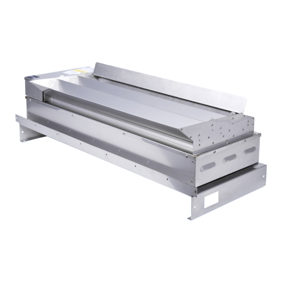
HUMIDIFIRST The Humidifirst DT series design gives you a choice of mounting the HUMIDIFIER MODULE BASE with the electrical and water connections facing upstream or downstream. This allows you to orientate the humidifier module base so that access to the connection points is the most convenient for your application. -
Page 11: Physical Dimensions Of The Humidifier Mounting Shelf
HUMIDIFIRST DT SERIES MOUNTING SHELF Mount the humidifier module here 1.5” (four mounting holes) 3” Attach to ductwork/AHU here 10.5” (four mounting holes - field supplied screws) 15.1” (DT60, DT80) DIRECTION OF AIR FLOW 3” 4.5” .875” .875” FRONT VI EW... -
Page 12: Master Panel Sizes
HUMIDIFIRST The Master Panel The Master Panel powers and controls the humidifier modules. It interfaces with sensors located in the facility and will energize the humidifier module(s). All power for the humidifier module(s) comes from the Master Panel. One (1) transformer, one (1) solid state relay, and one (1) solenoid valve relay are provided for each humidifier module. -
Page 13: Racking Sizes For Humidifier Mounting
The installer may wish to provide the racking, or it can be provided optionally by Humidifirst. The humidifiers should never be placed one in front of the other. The racking system places one above the other. The maximum number of modules per rack is five (5). -
Page 14: Specification For The Humidifier Module
HUMIDIFIER MODULE SPECIFICATIONS The ultrasonic humidification system shall include packaged, self-contained ultrasonic humidifier module(s) using the principle of ultrasonic nebulization. Each transducer circuit shall use the “thickness vibration method” of humidification via a piezoelectric converter. The ultrasonic transducers shall convert the electric energy into mechanical energy, causing the water to cavitate, resulting in the production on one micron sized water particles. - Page 15 HUMIDIFIER MODULE - continued Each humidifier shall have the following components: A. Solenoid valve to control water flow into the humidifier B. Float switch to control water level. C. Float switch to provide for low water shutdown D. Piezoelectric crystals (transducers) Mist discharge diffuser The mist discharge diffuser shall be adjustable so that when field conditions dictate higher velocities, air can be restricted and small droplet size can be maintained.
-
Page 16: Field Wiring Schematic For Hc-300 Microprocessor
HUMIDIFIRST Field Wiring Schematic for HC-300 Controller Field wiring to Master Panel MASTER PANEL ◄ Common alarm (2 wire dry contact signal) HUMIDIFIRST ◄ Air proving circuit 1. Microprocessor (2 wire- 24 Vdc) 2. Solid state relays ◄ Remote shut down (2 wire- 24Vdc) 3. -
Page 17: Field Wiring Sizing Chart
HUMIDIFIRST Transducer power wire sizing from the Master Panel to the humidifier module(s) Field wiring for transducer power (hot and common) typically has a voltage range of 42 to 50 volts. Check the wiring diagram for number of transducer rows, depending on the model they will vary from 1 to 3 rows. -
Page 18: Location Of Humidifier Modules And Master Panel
HUMIDIFIRST Layout of your Humidifirst Ultrasonic humidification system Locating the humidifier module(s) Properly locating the humidifier module(s) is very important and by doing so will eliminate many potential problems. Adequate air velocity (speed and direction), temperature, turbulence and return air relative humidity all play a role in the distance required for full evaporation. -
Page 19: Air Flow Safety Switch Physical Data
AIR PRESSURE SWITCH 1/4" OD TUBE CONNECTION POINT HIGH PRESSURE LOW PRESSURE SENSITIVITY ADJUSTMENT .187"DIA. SCREW MOUNTING HOLE 6.25" TERMINAL & SENSITIVITY SCREW COVER 2.81" WIRE PUNCH OUT FIELD WIRING TERMINALS 3.75" 3.79" 1. The air pressure switch must be mounted to a vertival surface, as this device is gravity sensitive. -
Page 20: Location Of The Humidity Sensors
HUMIDIFIRST Locating the humidity sensors Two styles of humidity sensors are available for sensing the relative humidity – wall mount or duct mount. Each offers unique features and benefits. Please consult the factory to determine the best sensor(s) for your application. -
Page 21: Design Of Ductwork Or Air Handler Applications
Humidifirst’s engineering department to discuss your application. The following are important items to consider: 1. Humidifirst humidifier modules are designed and tested to operate in air velocities between 300 to 1500 feet per minute (FPM) (velocity of air passing above the humidifier module). -
Page 22: Positioning Humidifier Modules In Air Handlers (Ahu)
HUMIDIFIRST FOR AHU INSTALLATIONS Humidifier ideal module placement (see note on page 21) 8” minimum between top module and AHU AIR DIRECTION 6” minimum between modules 4” minimum between bottom module and AHU Suggested evaporation distance is 72” 6”- 10” minimum between coil and humidifier module This AHU section should have a sealed drain pan in full length of the base Position the humidifier modules in from either side a minimum of 4”... -
Page 23: Positioning Humidifier Modules In Ductwork
HUMIDIFIRST FOR DUCT INSTALLATIONS Humidifier ideal module placement (see note 5 on page 21) 8” minimum between top module and duct AIR DIRECTION 6” minimum between modules (typical) 4” minimum between bottom module and duct d” OPTION ONE – MOUNTING THE HUMIDIFIER MODULES VERTICALLY d”... -
Page 24: Mechanical
4. See the previous page for suggested humidifier module mounting positions. 5. Humidifirst humidifier modules are designed and tested to operate in air velocities between 300 to 1500 feet per minute (FPM) (velocity of air passing over the humidifier module). -
Page 25: Water
4. Reverse osmosis systems with de-ionization polishing or just de-ionization bottles are typically used for water treatment. Please contact Humidifirst for sizing and/or selection of water treatment equipment. Undersized water treatment systems can cause damage to the humidification system. - Page 26 HUMIDIFIRST READ THIS MANUAL before starting the humidification system CAUTION !! 1. It is recommended at the initial humidifier start up to cover the transducers with one inch of water. This will reduce the chance of damaging the transducers if the field wiring is incorrect.
- Page 27 Make sure the drain plug on the humidifier module(s) is secure and tight. 1. Before the Humidifirst humidification system is started, the lines that supply water to the humidifier modules should be flushed for 15-20 minutes to ensure that any small particles do not wedge in the solenoid valve and prevent it from closing.
-
Page 28: Start-Up Precautions
HUMIDIFIRST START-UP (continued) 9. To verify that the units are filling with water, briefly lift the mist diffuser of the humidifier module and visually inspect the water. 10. Once the humidifier module is full, the “low water safety” relay will switch to the “on”... -
Page 29: Humidity Sensor
HUMIDIFIRST START-UP TROUBLE SHOOTING (continued) Humidity sensors 1. Another possible problem at start-up is the sensor. The wiring diagram shows the connections that need to be made for the sensor to operate properly. 2. Make sure that the humidity sensors are placed in the proper location. For duct sensors, the control sensor should be located in the return air duct. -
Page 30: Humidifier Modules
HUMIDIFIRST START-UP TROUBLE SHOOTING (continued) Humidifier modules The humidifier module may have one of the following problems: 1. If the humidification system will not operate, first make sure that there is a call for humidification and that the humidifier set-point is higher than the relative humidity in the space. -
Page 31: Trouble Shooting After The System Has Been Started
HUMIDIFIRST Trouble shooting after the humidifier has operated for a period of time The transducers are so covered with deposits that they do not work properly and the “finger” column of water is very small and puts out little mist. The transducers must be kept clean. -
Page 32: Dt - Series Explosion View
DT – SERIES EXPLOSION VIEW... -
Page 33: Maintenance
MAINTENANCE General Maintenance - Humidifier module(s) Maintenance of Humidifirst ultrasonic humidifiers is simple and plays an important part in keeping the humidifier modules operating properly and extending the life of the components inside. Not later than one month after start-up, the humidifier modules should be inspected for cleanliness. -
Page 34: Sensors
Owner’s Manual Disclaimer Humidifirst has made every effort to ensure accuracy in the manual, and assumes no responsibility and disclaims all liability for damages resulting from the use of this information or for any errors or omissions. -
Page 35: Dt Series Start-Up Form
YOU and/or the humidification system. Please complete the following checklist and return it to Humidifirst (1520 Neptune Dr., Suite A, Boynton Beach, FL 33426, Attn: Start-up). There will be no warranty of the equipment without the form being completed and returned. - Page 36 HUMIDIFIRST page 2 of 8 HUMIDIFIRST DT-SERIES START-UP FORM Master Panel serial number: Name of person doing start-up: The following items can be completed without operating the humidification system: Location of humidifier module(s). A. The distance upstream of the first humidifier...
- Page 37 HUMIDIFIRST page 3 of 8 HUMIDIFIRST DT-SERIES START-UP FORM Master Panel serial number: Record the distance from the Master panel: A. to the humidifier module(s). feet B. to the conductivity probe. feet Record the gauge of the wires connecting the Master Panel to the humidifier module(s).
- Page 38 HUMIDIFIRST page 4 of 8 HUMIDIFIRST DT-SERIES START-UP FORM Master Panel serial number: Name of person doing start-up: 14. Has the air safety switch been connected? Yes ______ No ______ Is the air safety switch wired directly to the Master Panel?
- Page 39 HUMIDIFIRST page 5 of 8 HUMIDIFIRST DT-SERIES START-UP FORM Master Panel serial number: Name of person doing start-up: The following items should be inspected with the humidification system energized and the humidifier module(s) operating. Make sure that there is water connected and flowing.
- Page 40 HUMIDIFIRST page 6 of 8 HUMIDIFIRST DT-SERIES START-UP FORM Master Panel serial number: Name of person doing start-up: Humidifier module Power reading Sol. valve Trans Transducer Amperage volts volts Row 1 Row 2 Row 3 #1 @ Panel #1 @ DT...
- Page 41 HUMIDIFIRST page 7 of 8 HUMIDIFIRST DT-SERIES START-UP FORM Master Panel serial number: Name of person doing start-up: Humidifier module Power reading Sol. valve Trans Transducer Amperage volts volts Row 1 Row 2 Row 3 #8 @ Panel #8 @ DT...
- Page 42 HUMIDIFIRST page 8 of 8 HUMIDIFIRST DT-SERIES START-UP FORM Master Panel serial number Name of person doing start-up: Notes from start-up:...
- Page 43 HUMIDIFIRST ULTRASONIC HUMIDIFIERS 1520 Neptune Dr., Suite A, Boynton Beach, FL 33426 (561) 752-1936 FAX (801) 760-2777 www.humidifirst.com...
Need help?
Do you have a question about the DT Series and is the answer not in the manual?
Questions and answers