Burkert 8695 Quick Start Manual
Control head
Hide thumbs
Also See for 8695:
- Operating instructions manual (192 pages) ,
- Quick start manual (64 pages) ,
- Quick start manual (82 pages)

Related Manuals for Burkert 8695


Summary of Contents for Burkert 8695
- Page 1 Type 8695 Control Head Steuerkopf Tête de commande Quickstart English Deutsch Français...
- Page 2 We reserve the right to make technical changes without notice. Technische Änderungen vorbehalten. Sous réserve de modifications techniques. © Bürkert Werke GmbH & Co. KG, 2007 - 2018 Quickstart 1805/07_EU-ML_00805384 / Original DE...
-
Page 3: Table Of Contents
Type 8695 Table of Contents 7.4 Manual actuation of the actuator via pilot valves ..15 QUICKSTART ................ 4 1.1 Definition of term / abbreviation ........4 PNEUMATIC INSTALLATION ..........16 1.2 Symbols ............... 4 ELECTRICAL INSTALLATION / DISPLAY ELEMENTS ..17 AUTHORIZED USE ............... 5 9.1 Safety instructions ............. 17 9.2 Electrical installation 24 V DC ........ -
Page 4: Quickstart
Type 8695 QUICKSTART Symbols The following symbols are used in these instructions. The Quickstart describe the entire life cycle of the device. Keep the Quickstart in a location which is easily accessible to every user and DANGER! make the Quickstart available to every new owner of the device. Warns of an immediate danger. ▶ Failure to observe the warning may result in a fatal or serious Important Safety Information. injury. Read Quickstart carefully and thoroughly. Study in particular the chapters entitled “Basic safety instructions” and WARNING! “Authorized use”. ▶ Quickstart must be read and understood. Warns of a potentially dangerous situation. ▶ Failure to observe the warning may result in serious injuries or death. -
Page 5: Authorized Use
Type 8695 Authorized use AUTHORIZED USE BASIC SAFETY INSTRUCTIONS These safety instructions do not make allowance for any Non-authorized use of the control head Type 8695 may be a • contingencies and events which may arise during the installation, hazard to people, nearby equipment and the environment. operation and maintenance of the devices. The device is designed to be mounted on pneumatic actuators • local safety regulations – the operator is responsible for observing of process valves for the control of media. these regulations, also with reference to the installation personnel. ▶ In the potentially explosion-risk area the control head Type 8695 may be used only according to the specification on the separate approval sticker. For use observe the additional instructions... -
Page 6: General Information
Type 8695 General information GENERAL INFORMATION General hazardous situations. To prevent injury, ensure: Contact address ▶ Installation and repair work may be carried out by authorized Germany technicians only and with the appropriate tools. Bürkert Fluid Control System ▶ After an interruption in the power supply or pneumatic Sales Center supply, ensure that the process is restarted in a defined or Chr.-Bürkert-Str. 13-17 controlled manner. D-74653 Ingelfingen ▶ The device may be operated only when in perfect condition Tel. + 49 (0) 7940 - 10 91 111 and in consideration of the operating instructions. Fax + 49 (0) 7940 - 10 91 448 ▶ The general rules of technology apply to application planning E-mail: info@burkert.com and operation of the device. International To prevent damage to property on the device, ensure: Contact addresses can be found on the final pages of the printed ▶ Do not feed any aggressive or flammable media into the pilot operating instructions. -
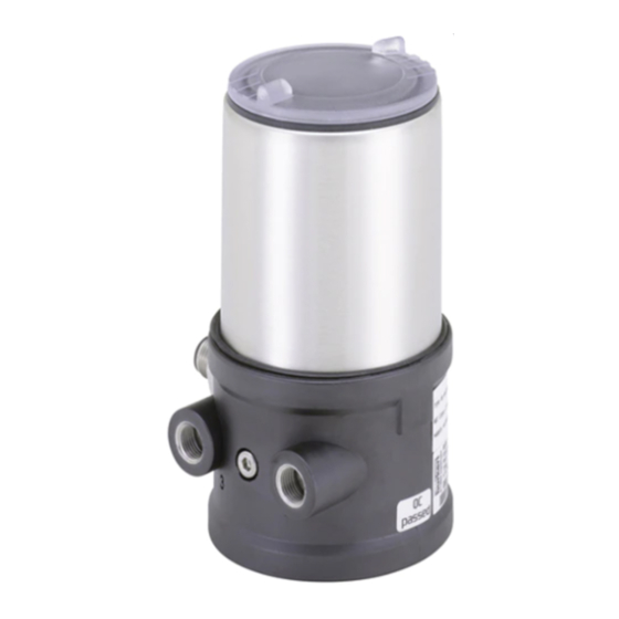
Page 7: System Description
Type 8695 System description SYSTEM DESCRIPTION The control head Type 8695 has been optimized for the integrated modular fitting of series 21xx process valves (Element) with actuator Structure and function size ∅ 50. Various expansion stages are possible thanks to the modular design. The control head Type 8695 can control single or double-acting process valves. For installation on the 20xx series (Classic) there is a special model. View without transparent cap, series 21xx: Control head Teach function Pressure limiting valve (for pro- tection against too high internal pressure in case of error) Actuator Electrical connection Circular plug-in connector M12 x 1 Process valve Connection housing Valve body Exhaust air port (label: 3) Fig. -
Page 8: Technical Data
Type 8695 Technical data TECHNICAL DATA Operating conditions Conformity WARNING! In accordance with the EU Declaration of conformity, the control Solar radiation and temperature fluctuations may cause mal- head Type 8695 is compliant with the EU Directives. functions or leaks. ▶ If the device is used outdoors, do not expose it unprotected Standards to the weather conditions. The applied standards on the basis of which compliance with the ▶ Ensure that the permitted ambient temperature does not EU Directives is confirmed are listed in the EU type examination exceed the maximum value or drop below the minimum value. certificate and/or the EU Declaration of Conformity. Ambient temperature see type label Licenses Degree of protection The product is approved for use in zone 2 and 22 in accordance with ATEX directive 2014/34/EU category 3GD. Evaluated by the... -
Page 9: Type Labels
Type 8695 Technical data Stroke range of valve spindle 6.6.2 UL type label (example) 2 1xx series (Element) Type; Features of the type code applicable to UL and 20xx series (Classic) AS-Interface 2 – 25 mm and ATEX Control function; pilot valve; 24 V DC 2 – 35 mm Supply voltage pilot valve DeviceNet 2 – 35 mm 8695 -E1-...-0 PU02 Third-party devices Single act Pilot 0.6 24V Max. operating pressure Pmax 7 bar (modified guide element Tamb -10 - +55 °C Max. ambient temperature required) AS-Interface 2 – 34 mm S/N 1001 24 V DC 2 – 44 mm Serial number / CE mark 00123456 W15MA DeviceNet 2 – 44 mm... -
Page 10: Pneumatic Data
Type 8695 Technical data Pneumatic data Electrical data Control medium n eutral gases, air WARNING! Quality classes in accordance with ISO 8573-1 Only circuits with limited power may be used for UL approved Dust content C lass 7 max. particle size 40 µm, components according to “NEC Class 2”. max. particle density 10 mg/m³ 6.8.1 Electrical data without bus control Water content Class 3 m ax. pressure dew point 24 V DC - 20 °C or min. 10 °C below the lowest operating temperature Protection class 3 as per DIN EN 61140 (VDE 0140-1) Oil content Class X max. 25 mg/m³... -
Page 11: Installation
Type 8695 Installation INSTALLATION Supply voltage 2 9.5 V – 31.6 V DC (according to specification) Only for control head without pre-assembled process Outputs valve. M ax. switching capacity 1 W via AS-Interface Watchdog function integrated Max. power consumption 120 mA Safety instructions Power consumption input during normal operation DANGER! (after current reduction; valve + 1 end position reached) 90 mA Risk of injury from high pressure in the equipment/device. ▶ Before working on equipment or device, switch off the pressure 6.8.3 Electrical data with DeviceNet bus control and deaerate/drain lines. -
Page 12: Installation Of The Control Head On Process Valves Of Series 21Xx
Type 8695 Installation Installation of the control head on → Push the control head, without turning it, onto the actuator until no gap is visible on the form seal. process valves of series 21xx NOTE! NOTE! When mounting on process valves with a welded body, follow Too high torque when screwing in the fastening screw does the installation instructions in the operating instructions for not ensure protection class IP65 / IP67. -
Page 13: Installation Of The Control Head On Process Valves Of Series 20Xx
Type 8695 Installation Installation of the control head on Ensure that the pneumatic connections of the control process valves of series 20xx head and those of the valve actuator are situated pref- erably vertically one above the other (see “Fig. 9”). Procedure: Guide rail NOTE! Too high torque when screwing in the fastening screw does not ensure protection class IP65 / IP67. ▶ The fastening screws may be tightened to a maximum torque of 1.5 Nm only. - Page 14 Type 8695 Installation → Screw the plug-in hose connectors onto the control head and Control function A (CFA) the actuator. Process valve closed in rest position (by spring force) → Using the hoses supplied in the accessory kit, make the Pilot air outlet pneumatic connection between the control head and actuator with the “Tab. 1: Pneumatic connection to actuator”. Upper pilot air port NOTE! Lower pilot air port Damage or malfunction due to ingress of dirt and moisture. ▶ To comply with protection class IP65 / IP67, connect the Control function B (CFB) pilot air outlet (only for CFA or CFB) which is not required to Process valve open in rest position (by spring force) the free pilot air port of the actuator or seal with a plug. Pilot air outlet “In rest position” means that the pilot valves of the...
-
Page 15: Manual Actuation Of The Actuator Via Pilot Valves
Type 8695 Installation Manual actuation of the actuator via Move actuator to end position pilot valve → Turn the hand lever to the right using a screwdriver. The actuator can be moved without a power supply from the rest Note: Do not press the hand lever when turning it position to its end position and back again, when the control air is connected. To do this, the pilot valve must be actuated with a screwdriver. Move actuator back to the rest position → Turn the hand lever to the left using a screwdriver. NOTE! The hand lever may be damaged if it is simultaneously... -
Page 16: Pneumatic Installation
Type 8695 Pneumatic installation PNEUMATIC INSTALLATION Important information for the problem-free functioning of the device: DANGER! ▶ The installation must not cause back pressure to build Risk of injury from high pressure in the equipment/device. ▶ Select a hose for the connection with an adequate ▶ Before working on equipment or device, switch off the pressure cross-section. and deaerate/drain lines. ▶ The exhaust air line must be designed in such a way that no water or other liquid can get into the device through WARNING! the exhaust air port. Risk of injury from improper installation. ▶ Installation may be carried out by authorized technicians only and with the appropriate tools. -
Page 17: Electrical Installation / Display Elements
Type 8695 Electrical installation / display elements ELECTRICAL INSTALLATION / DISPLAY ELEMENTS Safety instructions DANGER! Risk of electric shock. ▶ Before working on equipment or device, switch off the power Fig. 12: Circular plug M12 x 1, 8-pole supply and secure to prevent reactivation. ▶ Observe applicable accident prevention and safety regulations for electrical equipment. Wire color Designation Configuration white Limit switch top IN 1 (=Top) -
Page 18: Display Elements 24 V Dc
Type 8695 Electrical installation / display elements Display elements 24 V DC End position LED green NOTE! Jumper for assignment of Breakage of the pneumatic connection pieces due to rota- end position LEDs tional impact. ▶ When unscrewing and screwing in the transparent cap, do not hold the actuator of the process valve but the connection Status LED yellow housing. End position LED yellow → Unscrew the transparent cap in a counter-clockwise direction. Valve LED yellow (pilot valve) Fig. 14: Display elements 24 V DC... -
Page 19: Electrical Installation As-Interface
AS-Interface bus line + Screws not used M12 plug-in connector Bus – AS-Interface bus line - branch circuit not used Fig. 16: Control head 8695 with multi-pole cable and ribbon cable Tab. 4: Pin assignment of circular plug-in connector for AS-Interface terminal → Connect the control head according to the table. Handling the ribbon cable terminal The teach function can now be used to automatically determine The multi-pole cable features a ribbon cable terminal - with M12 and read in the end positions of the valve (description of the plug-in connector branch circuit - for AS-Interface cable harness. -
Page 20: Programming Data
Type 8695 Electrical installation / display elements Display elements AS-Interface Procedure: → Open the ribbon cable terminal NOTE! (loosen screws and remove cover) Breakage of the pneumatic connection pieces due to rota- → Insert cable harness conclusively tional impact. → Close ribbon cable terminal again ▶ When unscrewing and screwing in the transparent cap, do → Tighten screws not hold the actuator of the process valve but the connection Slightly undo thread-forming screws housing (see “Fig. 13: Open control head”). (approx. 3/4 turn to the left) and position them on the existing End position LED green tapped bore and screw in. -
Page 21: Electrical Installation Devicenet
Type 8695 Electrical installation / display elements Electrical installation DeviceNet Bus LED Bus LED (green) (red) 9.7.1 Bus connection (circular connector M12 x POWER OFF 1, 5-pole, male) No data traffic (expired Watch Dog at The control head features a 5-pole micro-style circular connector. slave address does not equal 0) The following configuration conforms to the DeviceNet specification. flashing Slave address equals 0 → Connect the control head according to the table. Sensor supply overloaded or external flashing reset Tab. - Page 22 Type 8695 Electrical installation / display elements 9.7.2 Configuring the control head → Unscrew the transparent cap in a counter-clockwise direction. Setting the DIP switches Transparent cap Body casing Connection housing 1 2 3 4 5 6 7 8 Actuator Fig. 20: Open control head → Set the DIP switches according to the following tables. Settings of the DeviceNet address DIP switches for bus address MAC ID – Medium Access Control Identifier:...
-
Page 23: Display Elements Devicenet
Type 8695 Electrical installation / display elements Display elements DeviceNet Setting the baudrate Adjusting the control head to the baudrate of the network. NOTE! DIP 7 DIP 8 Baudrate Breakage of the pneumatic connection pieces due to rota- tional impact. 125 kBaud ▶ When unscrewing and screwing in the transparent cap, do 250 kBaud not hold the actuator of the process valve but the connection 500 kBaud housing (see “Fig. 20: Open control head”). - Page 24 Type 8695 Electrical installation / display elements Status of the bus status LED Color Status LED Teach function is Device status Explanation Troubleshooting flashing yellow running Device is not supplied Connect other with voltage devices, if the device flickers yellow Puck PCB not available Device has still not is the only network No power End position is lit green End position bottom ended Duplicate MAC subscriber, supply / LEDs ID Test (test lasts is lit yellow...
-
Page 25: Teach Function
Type 8695 Teach function TEACH FUNCTION Device status Explanation Troubleshooting The teach function can be used to automatically determine and Another device with read in the end positions of the valve. the same MAC ID Check baud rate address is in the circuit For the bus variant AS-Interface, the teach function can Critical fault If required, replace also be started via the bus protocol. No bus connection device due to communication For the bus variant DeviceNet, the teach function can problems also be started via the bus protocol as well as the com- municator software. Tab. 12: Status of the bus status LED Status of the device status LED 10.1... - Page 26 Type 8695 Teach function Procedure: NOTE! Key in recess for actuating the Teach Breakage of the pneumatic connection pieces due to rota- function (keep tional impact. pressed for approxi- ▶ When unscrewing and screwing in the transparent cap, do mately 5 seconds) not hold the actuator of the process valve but the connection housing. Transparent cap Fig. 23: Teach function Body casing →...
-
Page 27: Safety Positions
Type 8695 Safety positions SAFETY POSITIONS ACCESSORIES Designation Order no. Safety positions after failure of the auxiliary Actuator Connection cable M12 x 1, 8-pole 919061 Designation power system Assembly tool 674078 electrical pneumatic USB adapter for connection to a PC in 227093 conjunction with an extension cable single-acting Information at Communicator Control down down www.burkert.com function A Tab. 15: Accessories down 12.1... -
Page 28: Packaging, Transport, Storage
Type 8695 Packaging, Transport, Storage PACKAGING, TRANSPORT, STORAGE NOTE! Transport damages. Inadequately protected equipment may be damaged during transport. ▶ During transportation protect the device against wet and dirt in shock-resistant packaging. ▶ Avoid exceeding or dropping below the permitted storage temperature. Incorrect storage may damage the device. ▶ Store the device in a dry and dust-free location. ▶ Storage temperature -20 – +65 °C. Damage to the environment caused by device components contaminated with media. - Page 30 www.burkert.com...
Need help?
Do you have a question about the 8695 and is the answer not in the manual?
Questions and answers