APsystems QS1 Installation And User Manual
Microinverter
Hide thumbs
Also See for QS1:
- Quick installation manual (3 pages) ,
- Trouble shoot (3 pages) ,
- Quick installation manual (2 pages)
Table of Contents
Advertisement
Installation / User Manual
(For Canada)
ALTENERGY POWER SYSTEM Inc.
global.APsystems.com
APsystems Shanghai China
Rm.B403 No.188, Zhangyang Road, Pudong, Shanghai 200120,P.R.C
TEL: 021-3392-8205
EMAIL: info.global@APsystems.com
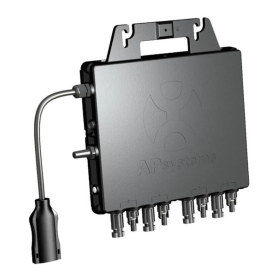
APsystems QS1 Microinverter
Rev 2.1
Please scan the QR code to get
mobile app and more support
to help the installation.
© All Rights Reserved
Advertisement
Table of Contents
Troubleshooting

Related Manuals for APsystems QS1


Summary of Contents for APsystems QS1
- Page 1 Installation / User Manual APsystems QS1 Microinverter Rev 2.1 (For Canada) ALTENERGY POWER SYSTEM Inc. global.APsystems.com Please scan the QR code to get APsystems Shanghai China mobile app and more support Rm.B403 No.188, Zhangyang Road, Pudong, Shanghai 200120,P.R.C to help the installation.
-
Page 2: Table Of Contents
4.3.3 Step 3 - Attach the APsystems Microinverters to the racking.............9 4.3.4 Step 4 - Ground the system....................... 10 4.3.5 Step 5 - Connect the APsystems microinverter to AC bus cable............10 4.3.6 Step 6 - Install a AC bus protective end cap at the end of AC bus cable.......... 10 4.3.7 Step 7 - Connect APsystems Microinverters to the PV Modules............ -
Page 3: Important Safety Instructions
APsystems Microinverter system and the solar-array. Be aware that the case of the APsystems Microinverter is the heat sink and can reach a temperature of 80°C. To reduce risk of burns, do not touch the case of the Microinverter. -
Page 4: Radio Interference Statement
A) Relocate the receiving antenna and keep it well away from the equipment. B) Consult the dealer or an experienced radio / TV technical for help. Changes or modifications not expressly approved by the party responsible for compliance may void the user’s authority to operate the equipment. QS1 Installation/User Manual... -
Page 5: Symbols Replace Words On The Equipment, On A Display, Or In Manuals
EMC and is authorized to energize, ground, and tag equipment, systems, and circuits in accordance with established safety procedures. The inverter and complete system may only be commissioned and operated by qualified personnel. QS1 Installation/User Manual... -
Page 6: Apsystems Microinverter System Introduction
2.APsystems Microinverter System Introduction The APsystems Microinverter is used in utility-interactive grid-tied applications, comprised of three key elements: APsystems Microinverter APsystems Energy Communication Unit (ECU) APsystems Energy Monitor and Analysis (EMA) web-based monitoring and analysis system Junction box... - Page 7 The distributed APsystems Microinverter system ensures that no single point of system failure exists across the PV system. APsystems Microinverters are designed to operate at full power at ambient outdoor temperatures of up to 149°F (65°C). The inverter case is designed for outdoor installation and complies with the IP67 environmental enclosure rating.
-
Page 8: Apsystems Microinverter Qs1 Introduction
3.APsystems Microinverter QS1 Introduction The APsystems QS1 Microinverter connect to single phase grid and can also be configured for 3-phase grid,and operates with most 60 and 72 cell PV modules.Contact APsystems Customer Support for checking compatibility.For more information, please see the Technical Data page (p.18) of this manual. -
Page 9: Apsystems Microinverter System Installation
4.APsystems Microinverter System Installation A PV system using APsystems Microinverters is simple to install. Each Microinverter easily mounts on the PV racking, directly beneath the PV module(s). Low voltage DC wires connect from the PV module directly to the Microinverter, eliminating the risk of high DC voltage. -
Page 10: Installation Procedures
Forbidden to hand carry the inverter through AC cable. 4.3.3 Step 3 - Attach the APsystems Microinverters to the racking Mark the location of the microinverter on the rack, taking into acount the position of the PV module junction box or any other obstructions. -
Page 11: Step 4 - Ground The System
Figure 3 4.3.5 Step 5 - Connect the APsystems microinverter to AC bus cable Push the microinverter AC connector into the trunk cable connector until you hear a "click". Try to remove it to check that it is properly locked. -
Page 12: Step 7 - Connect Apsystems Microinverters To The Pv Modules
PV connections. a. Each APsystems Microinverter has removable serial number labels. b. Peel labels off, affix one to the respective location on the APsystems installation map,and fill in 1,2,3 and 4 in the label below,according to the layout on the roof. - Page 13 Warranty Card on the mountingplate. Peel the label and affix it to the respective location on the APsystems The APsystems Installation Map is a diagram of the physical location of each microinverter in your PV installation. installation map. Each APsystems microinverter has a removable serial number label located on the mounting plate. Pee l the label Installation Map Template and affix it to the respective location on the APsystems installation map.
-
Page 14: Apsystems Microinverter System Operating Instructions
Once the ECU is plugged in and set up, it recognizes the microinverters, then the LED flashes green every 10 seconds. 5. The APsystems Microinverters will start to send performance data over ZigBee to the ECU. The time required for all the Microinverters in the system to report to the ECU will vary with the number of Microinverters in the system. -
Page 15: Troubleshooting
. Always disconnect AC power before disconnecting the PV module wires from the APsystems Microinverter. . The APsystems microinverter is powered by DC current of the PV module. After reconnecting DC, please check that the LED behaves as in 6.1.1 above. -
Page 16: Troubleshooting A Non-Operating Apsystems Microinverter
7. If the problem persists, please call APsystems Customer Support. Data of this manual. Do not attempt to repair the APsystems Microinverter. In the event of failure of the troubleshooting methods and after validation of the fault by the APsystems technical service, please return the defective microinverter to your distributor for replacement. -
Page 17: Replace A Microinverter
7.Replace a microinverter Follow the procedure to replace a failed APsystems Microinverter A. Disconnect the APsystems Microinverter from the PV Module, in the order shown below: 1. Disconnect the AC by turning off the branch circuit breaker. 2. Disconnect the inverter AC connector from the AC Bus. -
Page 18: Technical Data
APsystems Grid Support Details The QS1 is a grid support interactive inverter. This type of inverter is also known as a Grid Support Utility Interactive Inverter . The QS1 also comply with California Rule 21. The grid support function is controlled by ECU . - Page 19 Maximum slope of frequency droop [%Prated/Hz] Minimum slope of frequency droop [%Prated/Hz] SA15: Volt-Watt(VW) Output Power Rating[W] 1200 Output Power accuracy [W or %W] 5%Prated Maximum Slope of active power reduction[%Prated/V] Minimum Slope of active power reduction[%Prated/V] QS1 Installation/User Manual...
- Page 20 8.1 QS1 Microinverter Datasheet Region Canada Model QS1-NA Input Data (DC) Recommended PV Module Power (STC) Range 250Wp-440Wp+ MPPT Voltage Range 22V-48V Operation Voltage Range 16V-55V Maximum Input Voltage Startup Voltage Maximum Input Current 12A×4 Maximum DC short circuit current 15A×4...
-
Page 21: Wiring Diagram
< 59.3 0.16 +/-200ms *APsystems online Energy Management Analysis (EMA) platform © All Rights Reserved Specifications subject to change without notice - please ensure you are using the most recent update found at www.APsystems.com 2019/7/17 Rev2.1 9.Wiring Diagram QS1 Installation/User Manual... -
Page 22: Sample Wiring Diagram - Single Phase
9.Wiring Diagram Sample Wiring Diagram - Single Phase Figure11 QS1 Installation/User Manual... -
Page 23: Sample Wiring Diagram - 120D 208 3-Phase Grid
9.Wiring Diagram Sample Wiring Diagram - 120D 208 3-Phase Grid Figure12 QS1 Installation/User Manual... -
Page 24: Sample Wiring Diagram - 120Y 208 3-Phase Grid
9.Wiring Diagram Sample Wiring Diagram - 120Y 208 3-Phase Grid Figure13 QS1 Installation/User Manual... -
Page 25: Qs1 Accessory
10. QS1 Accessory 10.1 Wiring Diagram 8.AC Connector Male 9.AC Connector Female 5.Bus Cable Unlock Tool . 1 Bus Cable Grid 3.Bus Cable End Cap 4.Bus Cable Y CONN Cap 10.DC Extension Cable 6.DC Male Connector Cap 7.DC ale Connector Cap 2.AC Branch Extension Cable... -
Page 26: Accessories Summary
10.2 Accessories Summary Category Part NO. Name 2322301303 Y3 Bus Cable(12AWG,TC-ER cUL,2m,BK-RD-GN) Bus Cable 2322401303 Y3 Bus Cable(12AWG,TC-ER cUL,4m,BK-RD-GN) AC Branch Extension Cable 2334075242 Y3 Br. Ext-Cable(18AWG,TCER cUL,2m,BK-RD-GN) (On demand) Bus Cable End Cap 2060700007 3/4-wire Bus Cable End Cap Bus Cable Y-CONN Cap 2061702007 Bus Cable Y-CONN Cap... - Page 27 The APsystems Installation Map is a diagram of the physical location of each microinverter in your PV installation. Each APsystems microinverter has a removable serial number label located on the mounting plate. Peel the label and affix it to the respective location on the APsystems installation map.
Need help?
Do you have a question about the QS1 and is the answer not in the manual?
Questions and answers