Table of Contents
Advertisement
Available languages
Available languages
Quick Links
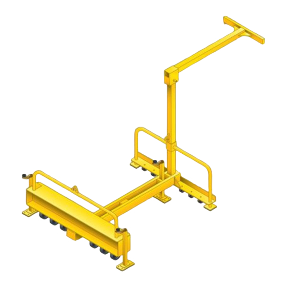
OPERATION & MAINTENANCE MANUAL FOR
®
The Miller
Edge™ and related equipment is designed to provide portable fall protection for workers
subjected to fall hazards during leading edge construction.
WARNING: ALL PERSONS USING THIS EQUIPMENT MUST READ, UNDERSTAND AND
FOLLOW ALL INSTRUCTIONS. FAILURE TO DO SO MAY RESULT IN SERIOUS INJURY OR
DEATH. PREGNANT WOMEN AND MINORS MUST NOT USE THIS PRODUCT.
THE
I211 Rev. C
9720101
Advertisement
Table of Contents

Related Manuals for Miller Edge


Summary of Contents for Miller Edge
- Page 1 OPERATION & MAINTENANCE MANUAL FOR ® The Miller Edge™ and related equipment is designed to provide portable fall protection for workers subjected to fall hazards during leading edge construction. WARNING: ALL PERSONS USING THIS EQUIPMENT MUST READ, UNDERSTAND AND FOLLOW ALL INSTRUCTIONS. FAILURE TO DO SO MAY RESULT IN SERIOUS INJURY OR DEATH.
-
Page 2: General Requirements
• Use only compatible locking snap hooks or locking carabiners with this product. • Use only approved Miller hardware with this product. • Do not attempt to move the unit while workers are attached. • Do not use unit on uneven or sloped surfaces greater than 5% from the horizontal. - Page 3 • INSTALLATION DISTANCE: Minimum installation distance from the front of the unit to the leading edge is 2 ft. Minimum installation distance from the side of the unit to the side leading edge is 3 ft. (Ref. fig. 10) •...
-
Page 4: Installation
II. INSTALLATION Before installation, it is recommended that the support structure meets or exceeds requirements specified General Requirements, Part B Limitations. Before installation of this equipment, User must read and understand all instructions and carefull inspect all equipment to ensure that it is in usable condition. User should familiarize his/herself with all components of this system. - Page 5 . SYS EM COMPONENT INSTALLATION: Unit As sembly Overview: Step 1. Install Vertical Boom Assembly. Step 2. Install Push Pin and Hitch pin. Step 3. Install Horizontal Boom Assemb Step 4. Install Push Pin and Hitch pin. Step 5. Inspect the installation and components of the unit before each use. nit Assembly Details: NOTE: For safety and ease of assembly, it is recommended that two or more workers trained in the...
- Page 6 Step 5. Ensure that cable is over the steering handles of th e Edge unit and not tallati Hole under, attach the carabiner to the pulley sheave and connect to the anchorage point.
- Page 7 Step 4. Ensure that cable is over the steering handles of the Edge unit and not under, attach the carabiner to the pulley sheave and...
-
Page 8: Installation Distance
(2) feet from the front of the unit to the leading edge of th e work surface and (3) feet from either side of e unit to the side edge of the work surface. Ref. fig. 10. WARNING: Do not use the system if installed less than the required distance from the edge. -
Page 9: Unit Inspection
3. Install only Miller retractable lifelines and use personal fall protection according to the manufacturer’s instructions supplied with that product. The personal fall protection used with this device must limit the fall arresting forces to 900 lbs. -
Page 10: Warning Labels
OR DEATH. DO NOT USE FOR FALL PROTECTION. LEADING USING ONLY ONE LIFTING RING MAY CAUSE THE DEVICE TO BRAKE ENGAGEMENT: EDGE BECOME UNSTABLE OR UNBALANCED WHILE LIFTING. ROTATE BRAKE HANDLE CLOCK- FAILURE TO FOLLOW MANUFACTURER'S INSTRUCTIONS WISE UNTIL HANDLE HAS MAY RESULT IN SERIOUS INJURY OR DEATH. -
Page 11: Inspection And Maintenance Log
LB522 LB523 PUNCH GRID ON DATE OF FIRST USE WARNING: Manufacturer's instructions su pplied with this pr oduct at the time of shipment must be followed. Fa ilure to do so ma y result in serious injury or death. SYSTEM CAPACITY RATING: Maximum nu mber of users m ust not exceed (2) two. - Page 12 MANUAL DE OPERACION Y MANTENIMIENTO “EDGE” ® l Edge™ de Miller y equipos relacionados están diseñados para proveer prote cción contra caídas ortátil para trabajado res sujetos a peligros de caída durante el desarrollo de trabajos en bordes en dificios de altura.
-
Page 13: Advertencias Y Limitaciones
• Utilice solamente gancho de doble bloqueo o carabineros compatibles con este producto. • Utilice solo productos duros (ganchos, líneas de vida autoretractiles) Miller con este producto. • No in tente mover la unidad mientras haya trabajadores conectados. - Page 14 B. LIMITACIO ® dge™ de Miller esta diseñado para su uso en superficies horizontales o con pendientes a < 5%. Las siguientes li mit ciones deben ser leídas, entendidas y seguidas antes de proceder a su instalación. • ESTRUCTURA DEL PISO: la estructura del piso donde esta unidad será utilizada no debe tener un espesor mínimo de 5/8”...
- Page 15 II. INSTALACION Antes de la ins talación, se recomienda que la estructura cumpla o exceda las exigencias especificadas en las Especific aciones G enerales, parte B Limitaciones. Antes de la instalación de este equipo, el usuario debe leer, entender todas las instrucciones e inspeccionar c uidadosamente todos los equipos para asegurar de que esta en condición de ser utilizado.
- Page 16 . INSTALACION DEL SISTEMA: esum en de l Ensamble de la unidad: aso 1. Instalación del ensamble de brazo vertical. Paso 2. Instalación del pasador y seguro para pasado Paso 3. Instalación del ensamble horizontal. Paso 4. Instalación del pasador y seguro para pasador.
- Page 17 evante de la unidad: ntes de intentar levantar la unidad, inspeccione la unidad y asegurece que todos los pasadores de unión están bien instalados y además que tienen instalados sus pasadores de seguridad correspondientes instalados correctamente. Para levantar la unidad solo utilice los anillos de levante provistos en figura 1.
- Page 18 Miller y utilice protección contra caídas de acuerdo a las instrucciones del fabricante que acompañan el producto. La protección contra caídas utilizada con esta unidad debe limitar las fuerzas de caída a 900 lbs (4kN) o menos y debe limitar la...
-
Page 19: Mantenimiento
Revisar todos los pernos por daño, fracturas, aflojado, desgaste y corrosión. Revise que cada pasador para ensamble este seguro en su posición e inspeccione por daño, desgaste, dobladura o partes rotas. Inspeccione cada componente por malfuncionamiento, ruptura, seguros o pernos faltantes. Reemplace si es necesario. - Page 20 BECOME UNSTABLE OR UNBALANCED WHILE LIFTING. WISE UNTIL HANDLE HAS FAILURE TO FOLLOW MANUFACTURER'S INSTRUCTIONS STOPPED. MAY RESULT IN SERIOUS INJURY OR DEATH. LEADING EDGE LB518 REV. A BRAKE DISENGAGEMENT: REVERSE ABOVE PROCEDURES LB520 REV. A LB530 REV. A LB522...
Need help?
Do you have a question about the Edge and is the answer not in the manual?
Questions and answers