
Related Manuals for Soca ST-680

Summary of Contents for Soca ST-680
- Page 1 ST-680 NETWORK PROXIMITY ACCESS CONTROL OPERATION AND INSTALLATION MANUAL SOCA TECHNOLOGY CO.,LTD. 2000 JULY...
-
Page 2: Table Of Contents
CONTENTS 1. Features introductions 2. Reader Front panel & types of proximity card 3. Operation instructions. Start reader Mode inquiry Anti-duress Setup mode 4. Quick setting 5. Setup mode function selection instructions (00 ~ 28) (01) Add new card (17) Auto record range (02) Delete card (18) Main reader location (04) Shunt time... -
Page 3: Features Introductions
ST-680 OPERATION INSTRUCTIONS 1. Features introductions When connecting with computer, it can be used for data inquiry and function setting ★ simultaneously. (Door open/close, start alarm system, etc). It can also operate solely to manage access control. Function setting can be done by computer or reader itself. (Single registration or deletion, ★... -
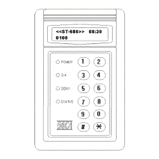
Page 4: Reader Front Panel & Types Of Proximity Card
* Anti-duress - It will operate when password and duress code are keyed in to send help signal to the nearest police station. It must be done manually to disable anti-duress function. * Exceed door shut time - Alarm will be activated, when door is not closed exceeding initial time setting control. -
Page 5: Operation Instructions
3. Operation instructions Start reader: It will begin self-testing function when power is switched on. Its operation procedures are as follow: LCD DISPLAY INSTRUCTIONS SRAM TESTING Memory testing RTC TESTING Real time clock testing INITIAL FUNCTION Initial system setting <<ST680>> 08:05 Model (ST680), present time (08:05), 10 registrations. - Page 6 4. Quick setup: SYSTEM FUNCTIONS User will get into the setup mode as the right diagram SELECTION : _ _ shown for any setting to be made. (A) Add new card , key in then key in 0 1 0...
- Page 7 Function (02) Delete card: Deletion of user’s card (such as loss of card or to prevent specific user to gain access) can be achieved by keying 8-digit card number indicated on the proximity card. Esc system function selection. Key in #or * status light on, display queuing 8-digit card number input, Go into system function setup.
- Page 8 Function (05) Door open mode: Reader has 2 types of identification modes. (pre-setting figure is 002) Mode (2). Card proximity door opening: The door will be opened, when the card is sensed. Mode (3). Door open by proximity card and password: The door will be opened by keying additional 4-digit password after sensing the registered card.
- Page 9 Function (08) Change system password: The reader’s password is being set at initially by manufacturer. In order to enter 5678 into system setting mode for the first time, user must key in the initial system password – 5 . User may change the system password after entering into system setting mode. 678...
- Page 10 Function (10) Reader ID number: Each reader has a reader ID number for computer identification and the number should not be repeated. (pre-setting figure is 001) Esc system function selection. Key in #or * status light on, display Queuing for reader ID Go into system function setup.
- Page 11 Function (12) Anti-duress code : Set up of anti-duress code ( ). (pre-setting code is *,0〜9 * Esc system function selection. Key in #or * Queuing for anti-duress status light on, display code input. Go into system function setup. Go into function 12. function selection.
- Page 12 Function (15) Set time: Example: 18 hour 00 minute 00 second => 18:00:00 (pre-setting figure is 00:00:00) Esc system function selection. Key in #or * status light on, display Queuing for system Go into system function setup. function selection. time input. Go into function 15.
- Page 13 Function (17) Auto Record range: This is to set under what kind of status to save by stand alone operation. (pre-setting figure is 003). There are 4 kinds of status to choose: A. Detect point / output action. (+1) B. Computer special command. (+2) C.
- Page 14 Function (19) Door shutting time: Time setting for sensing door-shutting time as to activate the alarm when exceeding the set value. (pre-setting value is 030) Esc system function selection. Key in #or * Queuing for door status light on, display Go into system function setup.
- Page 15 Function (21) Anti-duress alarm mode: (0) shows “ON”, (1) shows “OFF”. (pre-setting figure is 000). Once set at “ OFF “, anti-duress alarm will not function. Esc system function selection. Key in #or * Queuing for anti- status light on, display Go into system function setup.
- Page 16 Function (23) Anti-theft sensing mode: (0) shows “ON”, (1) shows “OFF”. (pre-setting figure is 000). Once set at “OFF”, the sensing mode will not function at any cases of broken in. Esc system function selection. Key in #or * Queuing for anti- status light on, display theft mode input.
- Page 17 Function (25) BEEP sound mode: (0) shows “ON”, (1) shows “OFF”. (pre-setting figure is 000). Once set at “ OFF “, the BEEP sound will not function. Esc system function selection. Key in #or * Queuing for BEEP status light on, display sound mode input.
- Page 18 Function (27) Anti-pass mode: (0) shows “ ON”, (1) shows “OFF”. (pre-setting figure is 001) Once set at “ON”, the card could only be used for matching single entry and exit. This is to prevent double entry by using the same card if card has been duplicated. Esc system function selection.
-
Page 19: Installation Instructions
Function (00) Instant door open: Authorized personnel could get into the setup mode to open the door when any emergency cases happened. Esc system function selection Key in #or * status light on, display Queuing for door Go into system function setup. function selection. - Page 20 (2) Wiring connection for additional electric lock and push button door open switch As of different types of electric lock, the wiring methods are also different . Overall, there are two types of wiring instructions as below: (a) Fail secure : 8 PIN Connector 8 PIN Connector R BK BR O Y G BL P...
-
Page 21: Wiring Connection For Additional Magnetic Door Sensing
(3)Wiring connection for additional magnetic door sensing (a) N.O. type magnetic spring : (b) N.C. type magnetic spring : 6 PIN Connector 6 PIN Connector N.C. type N.O. type magnetic spring magnetic spring R BR G BL P Y R BR G BL P Y (4) Wiring connection for anti-theft sensing. -
Page 22: Wiring Connection For Linking With Computer
(b) Anti-duress alarm : 8 PIN Connector 8 PIN Connector 6 PIN Connector 6 PIN Connector R BK BR O Y G BL P R BK BR O Y G BL P R BR G BL P Y R BR G BL P Y Alarm power Alarm power supply DC12V... -
Page 23: Hardware Specifications
7.HARDWARE SPECIFICATIONS Power supply : DC 12V / 1A, Adapter. Working environment : Temperature 0℃– 60℃, Humidity: 15% - 85%. : 16*2 STN LCD display with 4 LED’s indicators. Buttons : 12 stainless steel buttons. Real Time Clock : Internal equipped with a Real Time Clock (RTC) IC. : 128 KB memory. - Page 24 same time. If door is still not opened, please ensure that if the wiring or power supply of electric lock is installed properly or broken. 2. System password is entered but user cannot enter into various function selection of the setting mode.
- Page 25 APPENDIX A Installation Steps: Step 1, 2 Secure power supply wire and control wire through the base panel. Step 3 Fit the reader on the base panel (power supply wire and control wire must first be inserted and the wires must be arranged correctly) Step 4 Use enclosed key wrench and screws to mount the reader up.
Need help?
Do you have a question about the ST-680 and is the answer not in the manual?
Questions and answers