Table of Contents
Advertisement
Quick Links
Advertisement
Table of Contents

Related Manuals for Anthos A7 Plus


Summary of Contents for Anthos A7 Plus
- Page 1 97050825 Rev. 03 2017.03 ITALIANO...
-
Page 2: Table Of Contents
A7 Plus – OPERATOR'S MANUAL Contents GENERAL WARNINGS ....................................4 1.1. SYMBOLS ........................................4 1.2. INTENDED USE ......................................5 1.2.1. CLASSIFICATION AND REFERENCE STANDARDS ........................5 1.2.2. ENVIRONMENTAL CONDITIONS..............................5 1.2.2.1. TRANSPORT AND PACKAGING CONDITIONS ..........................5 1.2.3. WARRANTY .......................................5 1.2.4. DISPOSING THE EQUIPMENT WHEN NO LONGER USED ......................6 1.3. - Page 3 A7 Plus – OPERATOR'S MANUAL ASSISTANT’S BOARD OPERATION ................................71 6.1. ASSISTANT’S BOARD CONSOLE ................................71 6.2. SYRINGE ........................................72 6.3. T LED CURING LIGHT....................................72 6.4. C-U2 DENTAL CAMERA ................................... 72 6.5. SUCTION TUBES ..................................... 73 6.6. TRAY HOLDER ......................................74 6.7.
-
Page 4: General Warnings
A7 Plus – OPERATOR'S MANUAL GENERAL WARNINGS • These instructions explain how to correctly use the following dental units: A7 Plus CONTINENTAL A7 Plus INTERNATIONAL Please carefully read this manual before using the device. • The dental units described in this manual are manufactured by CEFLA s.c. - via Selice Prov.le 23/A - 40026 Imola (BO) Italy, a manufacturer complying with the European Directive on devices. -
Page 5: Intended Use
A7 Plus – OPERATOR'S MANUAL 1.2. INTENDED USE • The dental units described in this manual are Medical Devices intended for dental treatment. • The dentist's board may hold up to 6 instruments. • The assistant’s board can hold 2 suction tubes and 3 instruments. -
Page 6: Disposing The Equipment When No Longer Used
A7 Plus – OPERATOR'S MANUAL 1.2.4. DISPOSING THE EQUIPMENT WHEN NO LONGER USED In compliance with Directives 2011/65/EU and 2012/19/EU regarding restriction of the use of certain hazardous substances in electrical and electronic equipment along with waste electrical and electronic equipment, it is forbidden to dispose of this equipment in the municipal waste stream as unsorted municipal waste. - Page 7 A7 Plus – OPERATOR'S MANUAL • Quality of the water delivered by the dental unit. The user is responsible for the quality of the water delivered by the dental unit and must adopt measures to maintain the water quality. To ensure that delivered water is kept to quality standards, CEFLA s.c. recommends equipping the dental unit with an internal or external disinfection system.
-
Page 8: Cleaning And Disinfection
A7 Plus – OPERATOR'S MANUAL 1.4. CLEANING AND DISINFECTION Cleaning is the first step of any disinfecting process. Physically scrubbing with detergents and surface-active substances and rinsing with water removes a considerable amount of micro-organisms. If a surface is not clean first, the disinfecting process cannot be successful. -
Page 9: Description Of The Equipment
A7 Plus – OPERATOR'S MANUAL DESCRIPTION OF THE EQUIPMENT 2.1. IDENTIFICATION PLATES The plate is found on the arm between the dental chair and water unit. Data given on plate: • Manufacturer’s name. • Name of equipment. • Rated voltage. -
Page 10: Dental Chair
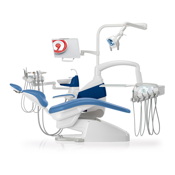
A7 Plus – OPERATOR'S MANUAL 2.3. DENTAL CHAIR Description of the parts. a Headrest. b Backrest. c Fixed armrest. d Right movable armrest ( optional ). e Safety foot board. Operating time. The operating and rest times are as follows: work 25 sec. -
Page 11: Safety Devices
A7 Plus – OPERATOR'S MANUAL Dental chair movement lock. With the instruments in rest position, dental chair movements can be disabled (see paragraph 5.1.1.2.5). Movement disabling is highlighted on the console display by the special icon (A). 4.1. SAFETY DEVICES •... -
Page 12: Adjustable Headrest
A7 Plus – OPERATOR'S MANUAL 4.3. ADJUSTABLE HEADREST The headrest may be of two types: (1) with manual cushion lock lever (2) with pneumatic cushion lock lever Adjusting headrest height. • with manual lock ( 1 ): The head rest blade is positioned through a magnetic clutch. The operator should pull up and/or push down the headrest until it is in the desired position. -
Page 13: Dentist's Board Operation
A7 Plus – OPERATOR'S MANUAL DENTIST'S BOARD OPERATION Layout of instruments. The positions of the instruments on the board are determined by the customer at the time of order. Activation of instruments. • The syringe is always on (see paragraph 5.3.). - Page 14 A7 Plus – OPERATOR'S MANUAL Tray holder for INTERNATIONAL board. WARNING: Maximum permitted load on the tray holder ( e ): 2 kg evenly distributed. Console unit position reversal (with reversible console, only). WARNING: Before carrying out this operation, turn the dental unit off.
- Page 15 A7 Plus – OPERATOR'S MANUAL Cleaning the dentist's board. Clean the dentist's board using a suitable product (see paragraph 1.4). NOTE for CONTINENTAL version instrument boards: instrument holder ( x ) can be removed to make cleaning operations easier; to remove it, simply extract it from its seat as it is fixed with magnets.
-
Page 16: Dentist's Control Console
A7 Plus – OPERATOR'S MANUAL 5.1. DENTIST’S CONTROL CONSOLE Dental units A7 are equipped with a dentist's console with touch-screen interface, consisting of a backlit multi-touch glass capacitive touch panel and a wide 5.7" colour TFT display, with LED backlighting, 640x480 pixel resolution and 16.7 million colour imaging. - Page 17 A7 Plus – OPERATOR'S MANUAL Warning icons. When icon button is touched on the display, warning icons can be displayed at any time; these icons show dental unit operating status. Displayed warning icons are: W.H.E. system working. Distilled water delivery on.
-
Page 18: User's Interface
After approximately 10 minutes of inactivity, the dental unit switches to the energy-saving status (standby); this status is signalled by the ANTHOS logo appearing on the console display. Standard operating conditions will be resumed as soon as any operation is carried out. -
Page 19: Operator Selection
A7 Plus – OPERATOR'S MANUAL 5.1.1.1. OPERATOR SELECTION The console allows managing 4 different operators. The following data can be set for each single operator: • Name of operator. • Turbine and scaler power adjustment. • 3 operating modes for electric micromotor. -
Page 20: Bioster Disinfection Cycle Setting
A7 Plus – OPERATOR'S MANUAL 5.1.1.2.1. BIOSTER DISINFECTION CYCLE SETTING This setting is the same for all operators. From MAIN SETTINGS menu, carry out the following operations: • Touch icon button to access the "BIOSTER disinfection cycle setting" sub-menu. NOTE: this sub-menu can be accessed also by keeping BIO button, located on assistant's board, pressed for at least 2 seconds. -
Page 21: Setting The Flusching Cycle
A7 Plus – OPERATOR'S MANUAL 5.1.1.2.2. SETTING THE FLUSCHING CYCLE This setting is the same for all operators. From MAIN SETTINGS menu, carry out the following operations: • Touch icon button to access the "FLUSHING cycle setting" sub- menu. NOTE: this sub-menu cannot be accessed if distilled water tank is in reserve (see paragraph 7.2.). - Page 22 A7 Plus – OPERATOR'S MANUAL 5.1.1.2.4. WATER-TO-BOWL SETTING From MAIN SETTINGS menu, touch the icon button to access the "Water to bowl setting" sub-menu including the following icon buttons: Bowl flushing controller with dental chair rinsing position recall with dental chair reset position recall.
-
Page 23: Bowl Automatic Movement Setting
A7 Plus – OPERATOR'S MANUAL 5.1.1.2.6. BOWL AUTOMATIC MOVEMENT SETTING From MAIN SETTINGS menu, touch icon button to access the "Bowl automatic movement setting" sub-menu including the following icon buttons: Bowl rotation controller with dental chair reset position call. Bowl rotation controller with dental chair rinsing position call. -
Page 24: Operating Light Setting
A7 Plus – OPERATOR'S MANUAL 5.1.1.2.8. OPERATING LIGHT SETTING From MAIN SETTINGS menu, touch icon button to access the OPERATING LIGHT SETTING sub-menu including the following icon buttons: Light turning off controller with dental chair rinsing position call. Light turning off controller with dental chair reset position call. -
Page 25: Data And Time Adjustment
A7 Plus – OPERATOR'S MANUAL • To adjust brake activation sensitivity, touch the relevant icon buttons NOTE: value setting range: 1 to 5. • To adjust display brightness, touch the relevant icon buttons NOTE: value setting range: 1 to 10. -
Page 26: Favourite Button Customization
A7 Plus – OPERATOR'S MANUAL 5.1.1.2.12. FAVOURITE BUTTON CUSTOMIZATION This sub-menu allows selecting the function to be associated to the icons appearing at the bottom of main screen. From the MAIN SETTINGS menu, touch icon button to access the FAVOURITE BUTTON CUSTOMIZATION sub-menu showing the positions that can be edited with the icons of the currently-set functions. -
Page 27: Language Selection
A7 Plus – OPERATOR'S MANUAL 5.1.1.2.14. LANGUAGE SELECTION This setting is the same for all operators. From the MAIN SETTINGS menu, touch icon button to access the LANGUAGE SELECTION sub-menu. • To edit language, touch the icon button of the corresponding flag. -
Page 28: Image Management
A7 Plus – OPERATOR'S MANUAL 5.1.1.2.16. IMAGE MANAGEMENT The dental image displaying and processing mode can be entered through the "Image management" screen. The images present in the dental unit local memory or in a USB key can be managed and the MYRAY iRYS image management software can be interfaced with (see paragraph 5.1.1.2.16.1.). -
Page 29: Image Management Through Irys
A7 Plus – OPERATOR'S MANUAL Delete image (a confirmation prompt will appear). Go back to "list" screen. Display images on monitor (only with monitor connected to camera module). "Image" screen. • Touch the image to zoom it and move it sideways. - Page 30 A7 Plus – OPERATOR'S MANUAL • Select the desired patient - the corresponding general data sheet will be displayed in order to be checked. • Touch icon button to access the “thumbnail” screen. "Thumbnail" screen. • Scroll image thumbnails by touching on the left or on the right of the central image.
-
Page 31: Apex Locator Setting
A7 Plus – OPERATOR'S MANUAL 5.1.1.2.17. APEX LOCATOR SETTING The alarm threshold of the electronic APEX LOCATOR (see paragraph 5.11.) can be set using this sub-menu. From the MAIN SETTINGS menu, touch icon button to access the APEX LOCATOR SETTING sub-menu. -
Page 32: Dental Chair Position Programming
A7 Plus – OPERATOR'S MANUAL 5.1.3. DENTAL CHAIR POSITION PROGRAMMING This setting is specific for each single operator. From main screen, carry out the following operations: • Bring the dental chair into the desired position using manual movement icon buttons. -
Page 33: Foot Control
A7 Plus – OPERATOR'S MANUAL 5.2. FOOT CONTROL 3 types of foot controls are available: (1) "Multifunction” foot control. (2) "Push-pedal” foot control. (3) "Power Pedal" foot control. NOTE: the "multifunction" and "push-pedal" foot controls can also be supplied in WIRELESS version. -
Page 34: Push-Pedal" Foot Control
A7 Plus – OPERATOR'S MANUAL Left-hand button operation ( 4 ). • Holding down the button for at least 2 seconds with instrument extracted: Chip-air control: sends a jet of air to the Turbine or the Micromotor. Air flow is activated by pressing the button; the jet of air is interrupted as soon as button is released. - Page 35 A7 Plus – OPERATOR'S MANUAL Control pedal ( 2 ). Operation: • Remove the instrument. • Push the control pedal ( a ) to start the instrument. • Adjust the rpm/power of the instrument with the control pedal: - to the right: increase;...
-
Page 36: Power Pedal" Foot Control
A7 Plus – OPERATOR'S MANUAL Right-hand button operation ( 5 ). Operation: • Holding down the button for at least 2 seconds with the instruments in rest position: Activation of the “Automatic dental chair return” programme. • Holding down the button for at least 2 seconds with instrument... - Page 37 A7 Plus – OPERATOR'S MANUAL Dental chair movement Joystick operation ( 3 ). It controls the following movements: Dental chair seat up. Dental chair backrest up. Dental chair seat down. Dental chair backrest down. To stop movement, release the control.
-
Page 38: Wireless Foot Control
A7 Plus – OPERATOR'S MANUAL • Lever pulled upwards: Dental chair programme “A" activation. Protection against liquid penetration. The foot control is protected against liquid penetration. Degree of protection: IPX1. Cleaning. Clean the foot control using a suitable product (see Paragraph 1.4). - Page 39 A7 Plus – OPERATOR'S MANUAL NOTE: this information can be also displayed on the TOUCH DISPLAY through the special icons ( A ) or ( B ) (see paragraph 5.1.) or inside the special menu controlling the foot control (see paragraph 5.1.1.2.3.).
-
Page 40: Syringe
A7 Plus – OPERATOR'S MANUAL 5.3. SYRINGE Description of the instrument. a Nozzle. b Handpiece. c Syringe release button. d Air button. e Water button. f Hot/cold selector (only for 6-function syringes). g Hot/cold indicator LED (only for 6-function syringes). -
Page 41: Turbine
A7 Plus – OPERATOR'S MANUAL Removing the grip. • The nozzle ( a ) is screwed onto the grip ( b ). • Turn the selector switch counter-clockwise (LED g off) and press button ( c ) to take the grip off the syringe casing. - Page 42 A7 Plus – OPERATOR'S MANUAL • To edit turbine rotating speed, touch icon buttons or scroll the relevant bargraph with your finger. • Use the foot control lever to start the instrument (see paragraph 5.2.). NOTE: the turbine cord can also be used to connect the air micromotors equipped with 4-way connector and conforming to ISO 13294 Standard - Dental Air Motor.
- Page 43 A7 Plus – OPERATOR'S MANUAL Activation/deactivation of Peristaltic pump (if installed, only). • To activate/deactivate peristaltic pump, simply touch the relevant icon button: Peristaltic pump not active. Peristaltic pump active with quantity delivered saline solution equal to 5. NOTE: pump activation is confirmed by the appearance of a relevant box next to the value of delivered saline solution.
- Page 44 A7 Plus – OPERATOR'S MANUAL 5.5. ELECTRIC MICROMOTOR Coupling the handpieces and changing the drill. Refer to the specific instructions provided with the micromotor and various handpieces. Use. WARNING: Also read the instructions for use of the various motors. The instrument is supplied non-sterile.
- Page 45 A7 Plus – OPERATOR'S MANUAL Spray to instrument control button. With the instrument in working position, select the type of delivered spray by touching the following icon buttons: Water + air spray operation. Water only spray operation. Operation without spray.
- Page 46 A7 Plus – OPERATOR'S MANUAL Micromotor working programme selection. The micromotor has 7 different working programmes that can be selected by touching the relevant icon button. NOTE: keep icon button pressed (for at least 2 seconds) to display a screen showing all the 7 available programmes.
-
Page 47: Restorative Operating Mode
A7 Plus – OPERATOR'S MANUAL • Press icon buttons to change the quantity of saline solution delivered by the peristaltic pump. NOTE: value setting range: 1 to 5. The quantity of solution delivered associated to the settable values is: - value 1: approx.35 cc/min, - value 2: approx.50 cc/min,... -
Page 48: Endodontic Operating Mode
A7 Plus – OPERATOR'S MANUAL Menu with micromotor extracted and active. The following functions can be changed: • drill max. rotation speed using icon buttons • current speed can be frozen with the following icon button: It sets current rotating speed as max. speed. - Page 49 A7 Plus – OPERATOR'S MANUAL • Customizable list for root canal drills control. - Press icon buttons to scroll the list of pre-set root canal drills. As soon as the new drill is selected, the corresponding speed and torque values will be automatically set.
-
Page 50: Root Canal Drill Customization Menu
A7 Plus – OPERATOR'S MANUAL Menu with micromotor extracted and active. The following functions can be changed: • drill max. rotation speed using icon buttons • handpiece calibration using the following icon button: It sets current set torque to 0. -
Page 51: Implant Operating Mode
A7 Plus – OPERATOR'S MANUAL 5.5.3. IMPLANT OPERATING MODE Characteristics. - speed value adjustable from 5 to 2500 Rpm with value always referring to drill, regardless of reduction ratio (reducers from 20:1 to 1000:1), - torque adjusting range; 0.5 to 55.0 Ncm for certified reducers, or 1 to... -
Page 52: Reduction Ratio Setting Menu
A7 Plus – OPERATOR'S MANUAL Menu with micromotor extracted and active. The following functions can be changed: • drill max. rotation speed using icon buttons • handpiece calibration using the following icon button: It sets current set torque to 0. -
Page 53: Reciprocating Operating Mode
A7 Plus – OPERATOR'S MANUAL 5.5.5. RECIPROCATING OPERATING MODE Characteristics. - 2 selectable reduction ratios: 4:1 and 6:1, - 3 selectable root canal drills, - progressive alarm signal starting from 60% of maximum set torque, Menu with micromotor extracted but not active. -
Page 54: Scaler
A7 Plus – OPERATOR'S MANUAL Menu with micromotor extracted and active. The only active icon button is the activation/deactivation of the alarm signal upon reaching the maximum set torque. 5.6. SCALER Connecting the handpiece and insert. Refer to the specific instructions provided with the handpiece. - Page 55 A7 Plus – OPERATOR'S MANUAL Scaler operating mode selection. Scaler working programme selection. • To adjust scaler power, touch icon buttons or scroll the bargraph with your finger. • Use the foot control lever to start the instrument (see paragraph 5.2.).
- Page 56 A7 Plus – OPERATOR'S MANUAL Scaler operating mode selection. With the instrument in working position, select the scaler operating mode by touching the following icon buttons: Standard operating mode. ENDO operating mode. PARO operating mode (ENDO with power reduced by 40%).
-
Page 57: T Led Curing Light
A7 Plus – OPERATOR'S MANUAL 5.7. T LED CURING LIGHT Technical specifications. Supply voltage: 24-36 VDC Max. power absorbed: 6 VA Light source: 1 5W LED Wavelength: 430-490 nm Acoustic signals: at cycle start, every 5 seconds, and at cycle end Type of operation: intermittent (work 3 consecutive cycles - rest 60 sec.) - Page 58 A7 Plus – OPERATOR'S MANUAL Operation. WARNING: The instrument is supplied non-sterile. Before use, disinfect the lamp grip. The fiber optic and the eye protection can be sterilised in a steam autoclave up to 135°C. • Put the fiber optic ( c ) in its housing until it clicks.
- Page 59 A7 Plus – OPERATOR'S MANUAL Indicators. The following indicators are provided on the control console to signal curing light fault: • LED 5 and LED 1, green, steady on. Lamp does not emit any light. Contact technical service department. • LED 5 and LED 2, green, steady on.
- Page 60 A7 Plus – OPERATOR'S MANUAL The handpiece cannot be put in autoclave; disinfect it on the outside with suitable products and cover it with disposable plastic wrap. Use soft disposable paper towels to disinfect the handpiece. Do not use harsh products or soak in liquids.
-
Page 61: C-U2 Dental Camera
A7 Plus – OPERATOR'S MANUAL 5.8. C-U2 DENTAL CAMERA The C-U2 dental camera system, complete with an extremely lightweight ergonomic handpiece, is specially designed for simple and well-conceived usability in examining the oral cavity. Auto-exposure and fixed focus features provide easy operation. This system is designed to allow the dentist to more efficiently show and explain to patients all oral conditions and reasons for planned treatment. - Page 62 A7 Plus – OPERATOR'S MANUAL • The main icon buttons available on the TOUCH DISPLAY are: Colour profile adjustment (only with camera extracted and set to LIVE). Camera LED turning on/off (only with camera extracted). Activation/deactivation of MIRROR function (only with camera extracted and set to LIVE).
- Page 63 A7 Plus – OPERATOR'S MANUAL MIRROR function. Touch icon button to shift from real to mirror image displaying mode. The icon corresponding to the active mode is shown on the TOUCH DISPLAY: Real image. Mirror image. NOTE: this function is available in LIVE mode, only.
- Page 64 A7 Plus – OPERATOR'S MANUAL Moving the captured images to an internal memory or a USB key. Each captured image is automatically stored inside console inner memory. To transfer all captured images inside a specific working folder, proceed as follows: •...
- Page 65 A7 Plus – OPERATOR'S MANUAL Handpiece status An optical guide, illuminated by a multicolour LED indicator, found in the area near the control button ( g ), shows handpiece status as per the table given below: Colour Situation Blue light flashes, very slowly...
-
Page 66: Zen-Xi Integrated Sensor
A7 Plus – OPERATOR'S MANUAL 5.9. ZEN-Xi INTEGRATED SENSOR The ZEN-Xi integrated sensor is a medical device used for the acquisition of intraoral X-rays in electronic format through the interface with the FULL TOUCH console or a Personal Computer. WARNING:... -
Page 67: Peristaltic Pump
A7 Plus – OPERATOR'S MANUAL • When the ZEN-Xi sensor is turned off or set to standby mode, the screen with the X-ray images taken is still shown on the TOUCH DISPLAY, to go back to main screen, simply touch icon button X-ray image displaying. - Page 68 A7 Plus – OPERATOR'S MANUAL • Secure irrigation line hose on instrument cord with the special plastic clips supplied with the sterile kit. NOTE: use type A for scaler cord, and type B for micromotor cord. Operation. To enable/disable peristaltic pump operation, extract micromotor and touch the relevant icon button: Peristaltic pump not active.
-
Page 69: Electronic Apex Locator
A7 Plus – OPERATOR'S MANUAL 5.11. ELECTRONIC APEX LOCATOR APEX LOCATOR, through the analysis of the variations of special electric signals, makes root apex location easier. If used together with a "file" (not supplied) for manual treatment, it proves useful also to measure canal length. - Page 70 A7 Plus – OPERATOR'S MANUAL APEX LOCATOR combined with electric micromotor. The APEX LOCATOR can also be used in combination with the electric micromotor when set to ENDO mode or to RECIPROCATING mode. When the APEX LOCATOR is enabled, if electric micromotor is...
-
Page 71: Assistant's Board Operation
A7 Plus – OPERATOR'S MANUAL ASSISTANT’S BOARD OPERATION Main features. • Two articulated arms secure board ( a ) to water unit ( b ) allowing it to be placed in the most convenient work position. Fixed arm (c) can turn by 120°. -
Page 72: Syringe
A7 Plus – OPERATOR'S MANUAL 6.2. SYRINGE For detailed information regarding operation of this instrument, see paragraph 5.3. 6.3. T LED CURING LIGHT For detailed information regarding operation of this instrument, see paragraph 5.7. 6.4. C-U2 DENTAL CAMERA For detailed information regarding operation of this instrument, see... -
Page 73: Suction Tubes
A7 Plus – OPERATOR'S MANUAL 6.5. SUCTION TUBES Suction starts by taking the tube off the board. To adjust suction power, use the slider ( a ) located on the suction tube holder grip. NOTE: suction tube suction control can be started/stopped by pressing the pedal (o) on water unit base. -
Page 74: Tray Holder
A7 Plus – OPERATOR'S MANUAL 6.6. TRAY HOLDER The tray holder module ( a ) is made of stainless steel and can easily be removed from its support. Tray holder support can rotate both clockwise and counter clockwise, so as to be positioned in the most convenient position for the operator. -
Page 75: Water Unit Operation
A7 Plus – OPERATOR'S MANUAL WATER UNIT OPERATION 7.1. FILL CUP AND BOWL The bowl can be turned by 305° on the water unit by hand or using a motor drive (optional). The bowl and the water-to-cup spout can be removed to make cleaning operations easier. -
Page 76: System
A7 Plus – OPERATOR'S MANUAL Bowl automatic movements (with motor-driven bowl, only). Bowl automatically moves: • by pressing "Dental chair rinsing position" button, NOTE: in this case, bowl position can also be set (see paragraph 5.1.2). • by pressing the "Dental chair reset position" button, To change this operating mode, see paragraph 5.1.1.2.6. -
Page 77: System (Water Hygienization Equipment)
A7 Plus – OPERATOR'S MANUAL WARNING: Use distilled water only. For enhanced hygiene, it can be added with 600 parts per million (ppm) of hydrogen peroxide using 20 ml of Peroxy Ag+ per litre of distilled water, or oxygenated water (20 ml of 3% oxygenated water per litre of distilled water). - Page 78 A7 Plus – OPERATOR'S MANUAL Disinfectant fluid running out warning. When the disinfectant fluid present inside tank (a) is running out, a special warning icon (H) appears on the TOUCH DISPLAY, an error message appears on the display and 3 warning BEEPS are emitted and repeated whenever dental unit is turned on.
-
Page 79: Bioster Disinfection Automatic System
A7 Plus – OPERATOR'S MANUAL 7.4. BIOSTER DISINFECTION AUTOMATIC SYSTEM Description of the system. This system allows carrying out an automatic disinfection cycle of the water circuits of the following instruments: • all instruments present on dentist's board, • the syringe present on the assistant's board, •... - Page 80 A7 Plus – OPERATOR'S MANUAL Performing the disinfection cycle. • Start the automatic disinfection cycle by touching icon button (see paragraph 5.1.1.2.1.) on the TOUCH DISPLAY or by pressing the BIO button on the assistant's board. • Now the system automatically performs the following operations:...
-
Page 81: Automatic Instrument Flushing Cycle
A7 Plus – OPERATOR'S MANUAL Error messages on console display. If system detects a malfunction, an error message will be displayed (see paragraph 10). WARNING: In case of irregular interruption of the disinfection cycle, the equipment will stay in lockout condition until the disinfection cycle is run again or a flushing cycle is carried out. -
Page 82: System (Automatic Cleaning Vacuum System)
A7 Plus – OPERATOR'S MANUAL 7.6. A.C.V.S. SYSTEM (AUTOMATIC CLEANING VACUUM SYSTEM) Description of the system. This system allows cleaning the surgical suction system. System features a tank ( c ) with detergent fluid and two couplings ( d ) used for suction tube flushing. -
Page 83: Opening/Closing The Water Unit Side Cover
A7 Plus – OPERATOR'S MANUAL 7.7. OPENING/CLOSING THE WATER UNIT SIDE COVER Opening the cover: • Disengage water unit side cover ( a ) after having operate the special locking handle ( h ). • Slide the cover to the left (see figure) and turn it to reach the complete opening. -
Page 84: Accessories
A7 Plus – OPERATOR'S MANUAL ACCESSORIES 8.1. OPERATING LAMP The operating light comes in 2 models: (1) Light with halogen light source, VENUS model. (2) Lamp with LED light source, VENUS PLUS-L model. The instructions for use and maintenance of the lamps are available in PDF format and can be downloaded from the download area of the website www.anthos.com. -
Page 85: Air/Water/230V Quick-Couplings
(see paragraph 7.2.). 8.5. AUXILIARY TRAY HOLDER Applied only on models A7 Plus SIDE DELIVERY. Tray holder can contain two standard size trays. Turn knob ( b ) to adjust vertical movement based on load: •... -
Page 86: Maintenance
A7 Plus – OPERATOR'S MANUAL MAINTENANCE Preventive maintenance CEFLA s.c., the manufacturer of the dental units, in accordance with applicable standards IEC 60601-1 3rd Ed. - 2007, IEC 62353 and directive MDD 93/42, and subsequent changes, for medical devices underlines that the preventive maintenance checks for the dental unit specified in the Technical care manual and Maintenance and warranty handbook are to be carried out by authorised personnel at least once every 12 months. -
Page 87: Cleaning The Surgical Suction Filter
A7 Plus – OPERATOR'S MANUAL 9.3. CLEANING THE SURGICAL SUCTION FILTER This operation should be done daily at the end of work. WARNING: Always wear goggles and gloves to prevent contact with infected material when cleaning the suction filters. Proceed as follows: •... -
Page 88: Cattani Surgical Separator
A7 Plus – OPERATOR'S MANUAL 9.5. CATTANI SURGICAL SEPARATOR At the beginning of each working day. Insert inside filter ( d ) a tablet ( v ) of VF CONTROL PLUS (CEFLA s.c.) WARNING: Always wear gloves to prevent contact with infected material when carrying out this operation. -
Page 89: Cleaning The Turbine Return Air Filter
A7 Plus – OPERATOR'S MANUAL Blocked drain pump signal. A special icon ( A ) on the TOUCH DISPLAY signals whether the drain pump located under separator reservoir is blocked. Now you are recommended to turn equipment off and manually empty the separator reservoir. -
Page 90: Metasys Amalgam Separator
When disposing of disposable containers full of amalgam, observe current local and national laws. 9.10. DENTAL CHAIR The dental chair does not need any special maintenance. In any case, operation should be checked by ANTHOS authorised personnel once a year. -
Page 91: Warning Messages
A7 Plus – OPERATOR'S MANUAL 10. WARNING MESSAGES M = Message on console display C = Cause R = Remedy M: "H2O reserve, fill tank" C: The level of fluid inside independent water supply tank has dropped below the min. level. - Page 92 A7 Plus – OPERATOR'S MANUAL M: "Foot board emergency activated" C: Dental chair has met an obstacle. R: Press "Seat up" button and remove the obstacle. M: "Backrest emergency activated" C: Dental chair backrest has met an obstacle. R: Press "Seat up" button and remove the obstacle.
-
Page 93: Technical Data
A7 Plus – OPERATOR'S MANUAL 11. TECHNICAL DATA Installation plan: 97042086 Water delivery flow rate: 10 l/min Technical manual: 97071156 Water consumption: 2 l/min. Dental unit spare parts catalogue: 97023117 Water hardness: < 25 °f (14 °d) Dental chair spare parts catalogue:... -
Page 94: Dimensional Characteristics
A7 Plus – OPERATOR'S MANUAL 11.1. DIMENSIONAL CHARACTERISTICS A7 PLUS CONTINENTAL MODEL DIMENSIONAL CHARACTERISTICS... - Page 95 A7 Plus – OPERATOR'S MANUAL A7 PLUS INTERNATIONAL MODEL DIMENSIONAL CHARACTERISTICS...
-
Page 96: Dental Unit Operating Unit Maintenance Plan
A7 Plus – OPERATOR'S MANUAL 12. DENTAL UNIT OPERATING UNIT MAINTENANCE PLAN WHEN PART SEE PARAGRAPH Drain condensate. See paragraph 9.2. Before starting the work day. CATTANI suction Insert inside each suction filter a tablet of VF CONTROL PLUS. See paragraph 9.5.
Need help?
Do you have a question about the A7 Plus and is the answer not in the manual?
Questions and answers