Table of Contents
Advertisement
Quick Links
OPERATING, MAINTENANCE
& PARTS MANUAL
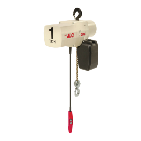
ELECTRIC CHAIN
JLC SERIES
Before installing hoist, fill in the information below.
Model Number.
Serial No.
Purchase Date
Please provide Serial Number when ordering parts.
MODEL NUMBERS:
JLC0232, JLC0516, JLC0532, JLC1016,
JLC1032, JLC2016, JLC4008
For JLCET models refer to this manual
and ETB680-1 for trolley information.
Follow all instructions and warnings for inspecting,
maintaining and operating this hoist.
The use of any hoist presents some risk of personal injury
or property damage. That risk is greatly increased if proper
instructions and warnings are not followed. Before using
this hoist, each operator should become thoroughly familiar
with all warnings, instructions and recommendations in this
manual. Retain this manual for future reference and use.
Forward this manual to hoist operator. Failure to operate
equipment as directed in the manual may cause injury.
Should you have any questions regarding this product,
please call Coffing Hoists at (800) 477-5003.
Assembled in USA with Imported and Domestic Components
JLC680-2 Rev AA April 2019
Advertisement
Table of Contents
Troubleshooting

Related Manuals for Columbus McKinnon Coffing JLC Series


Summary of Contents for Columbus McKinnon Coffing JLC Series
- Page 1 OPERATING, MAINTENANCE & PARTS MANUAL ELECTRIC CHAIN JLC SERIES Before installing hoist, fill in the information below. Model Number. Serial No. Purchase Date Please provide Serial Number when ordering parts. MODEL NUMBERS: JLC0232, JLC0516, JLC0532, JLC1016, JLC1032, JLC2016, JLC4008 For JLCET models refer to this manual and ETB680-1 for trolley information.
- Page 2 COFFING HOIST PARTS AND SERVICES ARE AVAILABLE IN THE UNITED STATES AND IN CANADA As a COFFING Hoist and Trolley user you are assured of reliable repair and parts services through a network of Master Parts Depots and Service Centers that are strategically located in the United States and Canada.
-
Page 3: Safety Precautions
SAFETY PRECAUTIONS 17. NOT operate beyond the limits of the load chain travel. Each Coffing JLC Series Electric Chain Hoist is built in accordance 18. NOT leave load supported by the hoist unattended unless with the specifications contained herein and at the time of specific precautions have been taken. -
Page 4: Operating And Safety Procedures
HOIST SAFETY IS UP TO YOU... DO NOT LIFT MORE THAN RATED LOAD. DO NOT PULL AT AN ANGLE. BE SURE HOIST AND LOAD ARE IN A STRAIGHT LINE. CHOOSE THE RIGHT HOIST FOR THE JOB... DO NOT USE LOAD CHAIN AS A SLING. Choose a hoist with the capacity for the job. -
Page 5: Table Of Contents
FOREWARD This manual contains important information to help you properly install, operate and maintain your hoist for maximum performance, economy and safety. Please study its contents thoroughly before putting your hoist into operation. By practicing correct operating procedures and by carrying out the recommended preventive maintenance suggestions, you will experience long, dependable and safe service. -
Page 6: General Information
SECTION I — INTRODUCTION 10. Before using the hoist, the operator should be certain that all personnel are clear. 1-1 GENERAL INFORMATION 11. Do not operate hoist with loads exceeding its rated capacity. 12. Supporting frames or beams used as a hoist hanger must have INSPECTION a greater load capacity than the hoist. -
Page 7: Specifications
SECTION II — SPECIFICATIONS Coffing JLC series electric chain hoists are rugged, portable hoists that provide quick, precise lifting. The hoists are constructed of Failure to comply with Safety precautions outlined throughout tough, but lightweight, die cast aluminum alloy housings. An oil bath this manual can result in serious injuries or death. -
Page 8: Installation Of Standard Chain Container
CHAIN CONTAINER (OPTIONAL ACCESSARY) retaining clip. Refer to Table 4. 4. Feed the remainder of chain into container by operating hoist in the “UP” direction to the top limit. This will permit the chain to For installations where the slack chain hanging from the hoist pile freely and prevent the chain from kinking, which may occur may be objectionable or hazardous, the use of a chain container if the chain is placed in the container by hand. -
Page 9: Overload Limiting Protection
SECTION IV — OPERATION SECTION V — MAINTENANCE 4-1 GENERAL 5-1. INSPECTIONS This hoist is designed for safe operation within the limits of its rated A planned inspection routine should be established for this hoist capacity. It is controlled by the “UP” and “DOWN” buttons of the based upon frequency of use, severity of use, and environmental pushbutton station. -
Page 10: Chains
Do not weld or join hoist load chain. Do not substitute another manufacturer's chain in this hoist. Damage or wear, beyond the stated limits, to any portion of the chain requires that the entire length of chain be replaced. CHAIN REPLACEMENT WITH CHAIN IN HOIST Refer to Figures 3 &... -
Page 11: Limit Switch Adjustment
“clicks” then turn two slots farther. Release the spring guide plate and be sure it slips back into the slots in both limit switch nuts. Do not disturb the silver slotted nut if it has been set previously. ADJUSTING LOWER LIMIT (SILVER NUT) Refer to Figure 3. -
Page 12: Hoist Controls
oil level fill plug from the side of the hoist. With the hoist hanging level, gear oil should be even with the hole. Change oil periodically depending on the severity of the application and the environmental conditions (at least every 200 hours of run time). BEARINGS All bearings except hook and idler sheave bearings are lubricated at the factory and should not require additional lubrication. -
Page 13: Assembled Gearing
3. Remove the transformer bolted to the back of the panel plate if it requires replacement. 4. Refer to Figure 15 to disassemble the brake. See BRAKE There are wires running through the hoist. Carefully ease the ADJUSTMENT on page 9 to properly set the brake. hoist sections apart. -
Page 14: Power Cord Precautions With 1-Phase Hoists
5-11 POWER CORD PRECAUTIONS WITH may be removed as follows: 1-PHASE HOISTS 1. Disconnect the Hoist and remove it to a workbench. Electric hoists require a sufficient power supply. It is especially 2. Remove the Hook Retaining Screw. important with single-phase voltage to ensure that the conductors 3. -
Page 15: Troubleshooting
VI — TROUBLESHOOTING Always disconnect unit from the power supply system before removing hoist covers or the back cover of control station Failure to follow proper lockout/tagout procedures may present the danger of electrical shock. TO AVOID INJURY: Disconnect power and lockout/tagout disconnecting means before removing cover or servicing this equipment Problem Probable Cause... -
Page 16: Troubleshooting
SECTION VI — TROUBLESHOOTING CONTINUED Problem Probable Cause Remedy 1. Excessive load. 1. Reduce load to within rated capacity of hoist. 2. Determine cause of low voltage and bring up to within plus or minus 10% of the voltage 2. Low voltage. specified on the motor. -
Page 17: Wiring
SECTION VII — WIRING Figure 9A — Wiring Diagram for 115/230V - 1 Phase Models Figure 9B — Wiring Diagram for 1-Speed, 230/460V - 3 Phase Models JLC680-2 Rev AA April 2019... -
Page 18: Wiring Diagram For 1- Speed, 208V & 575V 3 Phase Models
SECTION VII — WIRING CONTINUED Figure 9C — Wiring Diagram for 1-Speed, 208V and 575V - 3 Phase Models * Factory supplied diagrams will be numbered beginning with 985 for 575V and 987 for 208V. Figure 9D — Wiring Diagram for 2-Speed, 3 Phase Models * Factory supplied diagrams will be numbered beginning with 983 for 230 or 460V, 985 for 575V and 987 for 208V. -
Page 19: Inspection
SECTION VIII — INSPECTION INSPECTION To maintain continuous and satisfactory operation, a regular inspection procedure must be initiated to replace worn or damaged parts before they become unsafe. Inspection intervals must be determined by the individual application and are based on the type of service to which the hoist will be subjected. - Page 20 SECTION VII — INSPECTION CONTINUED INSPECTION AND MAINTENANCE CHECK LIST ELECTRIC POWERED OVERHEAD CHAIN HOIST Type of Hoist ________________________________________________ Capacity (Tons) ______________________________________________ Location ____________________________________________________ Original Installation Date ______________________________________ Manufacturer ________________________________________________ Manufacturer's Serial No. _____________________________________ Frequency of Inspection Frequent Periodic Possible Deficiencies Action Required Item Every 3 Months...
-
Page 21: Recommended Inspection And Maintenance Checklist . 18 10B Recommended Inspector's Report
SECTION VII — INSPECTION CONTINUED INSPECTOR’S REPORT ITEM REMARKS (LIST DEFICIENCIES AND RECOMMENDED ACTION) Inspector’s Date Signature Inspected Approved By Date Figure 10B - Recommended Inspector’s Report RECOMMENDED LUBRICATION SCHEDULE* COFFING ELECTRIC POWERED CHAIN HOIST Type of Service and Frequency of Lubrication. Page and Component Type of Lubricant... -
Page 22: Repair Parts
SECTION IX — REPAIR PARTS LIST Using “Commercial” or other manufacturer’s parts to repair the Coffing Hoists may cause load loss. TO AVOID INJURY: Use only Coffing supplied replacement parts. Parts may look alike but Coffing parts are made of specific materials or processed to achieve specific properties ORDERING INSTRUCTIONS The following information must accompany all correspondence... -
Page 23: Description
FIGURE 12 – BASIC HOIST Ref. no Description Part No. Ref. no Description Part No. JLC & Coffing Decal (Left Hand) JLC677-2L Motor (See Figures 13 & 14) JLC & Coffing Decal (Right Hand) JLC677-2R Cover Screw H2976P Capacity Decal 1/8 ton JM675K01 Trim Cover JM37... -
Page 24: Hoist Motor, 115/230V - 1 Phase
FIGURE 13 — HOIST MOTOR, 115/230V — 1 PHASE Refer to the motor nameplate for part number, voltage, full load amperage, horsepower, and other motor information. Parts List for Hoist Motor, 115/230V - 1 phase Ref. no Description Part No. Hoist Motor - 1/2 hp, 115/230V-1Ph 861JR12 Hoist Motor - 1 hp, 115/230V-1Ph... -
Page 25: Hoist Motor - 3 Phase
FIGURE 14 — HOIST MOTOR — 3 PHASE (‡) Refer to the motor nameplate for part number, voltage, full load amperage, horsepower, and other motor information. Parts List for Hoist Motor, 3 Phase Ref. no Description Part No. Ref. no Description Part No. -
Page 26: Brake & Solenoid Parts
FIGURE 15 — BRAKE & SOLENOID PARTS Parts List for Brake & Solenoid Parts Ref. no Description Part No. Ref. no Description Part No. Disc Brake Assembly* — Retainer JF710 1 hp,115 Volt 854JM1 Plate & Frame Assembly JF857 1/4 & 1/2 hp, 115 Volt 854JM12 Brake Coil* 1 hp, 230 Volt... -
Page 27: Electrical Parts - 1 Speed Models
FIGURE 16 — ELECTRICAL PARTS — 1-SPEED MODELS Parts List for Electrical Parts, 1-Speed Models Ref. no Description Part No. Ref. no Description Part No. 230/460V 909J10 Transmission Cover JM34-2 Terminal Block 115/230V 909J14 Panel Plate 257JM200 End Plate Reversing Contactor* 115/230V 909J15 1/2 hp &... -
Page 28: Electrical Parts - 2 Speed Models
FIGURE 17 — ELECTRICAL PARTS — 2-SPEED MODELS Parts List for Electrical Parts, 2-Speed Models Ref. no Description Part No. Ref. no Description Part No. Pri.: 230/460V, Sec.: 115V 821J431 Transmission Cover JM34-2 Pri.: 575V, Sec.: 24V 821J452 Panel Plate 257JM200 Pri.: 575V, Sec.: 115V 821J451... -
Page 29: 18 1 Speed Pushbutton Station
FIGURE 18 — 1-SPEED PUSHBUTTON STATION Parts List for Pushbutton, 1-Speed Ref. no Description Part No. Pushbutton Station and Control Cable Assembly 6 ft Cable Length PB2100-6 11 ft Cable Length PB2100-11 16 ft Cable Length PB2100-16 Pushbutton Station Assembly (2-Button, 1-Speed) 36900R Enclosure 36998R... -
Page 30: 19 2 Speed Pushbutton Station
FIGURE 19 — 2-SPEED PUSHBUTTON STATION Parts List for Pushbutton, 2-Speed Ref. no Description Part No. Pushbutton Station and Control Cable Assembly 6 ft Cable Length PB2200-6 11 ft Cable Length PB2200-11 16 ft Cable Length PB2200-16 Pushbutton Station Assembly (2-Button, 2-Speed) 36800R Enclosure 36998R... -
Page 31: Coffing Rocket Universal Pendant Control
FIGURE 20 - COFFING ROCKET UNIVERSAL PENDANT CONTROL 24*** 26**** Part No. Description *** 2-Speed Pendants ** Strain Relief Plate **** Screw Terminal Strip include 4 Switches Rocket Pendant Control - Single-Speed, ECUR-1S No E-stop Rocket Pendant Control - 2-Speed, ECUR-2S No E-stop 25 PACK: Rocket Pendant Control -... - Page 32 Part No. Ref No. Description Qty. Screw M3 x 1.34 x 35mm Lg Thd Roll Plstc Pendant Switch Rocker Plate Washer M3 x 6mm OD Sst Instruction Sheet ECUR-0011 Switch Repair Kit, 1 Speed, 2 Switch Switch Gasket Switch Housing Pin Hinge Retainer Plate Screw M3 X 1.34 X 16Mm Lg Thd Roll Plstc...
-
Page 33: Limit Switch Assembly
FIGURE 21 — LIMIT SWITCH ASSEMBLY Parts List for Limit Switch Assembly Ref. no Description Part No. Ref. no Description Part No. Transmission Cover JM34-2 Bushing JF531-4 Limit Switch Assembly (Includes items Limit Switch Shaft JF117-3S 918JG4 4-12) Limit Switch Nut (silver) SK6000-63Z Limit Switch Bracket Assembly 918JG3... -
Page 34: Long Lift Limit Switch Parts
FIGURE 22 — LONG LIFT LIMIT SWITCH PARTS Parts List for Long Lift Limit Switch Parts Ref. no Description Part No. Ref. no Description Part No. Transmission Cover JM34-2 Switch 815J1 Limit Switch Assembly (Includes items 6-32UNC X 1" Screw H1402P 944JG6 3-21) - Page 35 FIGURE 23 — TRANSMISSION JLC680-2 Rev AA April 2019...
- Page 36 FIGURE 23 —TRANSMISSION CONTINUED Parts List for Transmission Ref. no Description Part No. Sheave Housing JM33-1 Sheave Housing Gasket JM560-3 Transmission Housing JM35-1 Transmission Housing Gasket JM560-2 Transmission Cover JM34-2 Chain Guide JM273 Oil Plug - Drain/Fill H6297 Oil Seal 561K2 Screw Hex Washer Head Self-threading H2693P...
-
Page 37: Chaining Parts
FIGURE 24 — CHAINING PARTS JLC680-2 Rev AA April 2019... - Page 38 FIGURE 24 — CHAINING PARTS CONTINUED Parts List for Chaining Parts Ref. no Description Part No. Sheave Housing JM33-1 Transmission Housing JM35-1 Transmission Cover JM34-2 Electrical Cover JM36 Chain Support Pin (2 ton only) JM111 Chain Support (2 ton only) JM109 Chain Stripper JM254...
- Page 39 NOTES JLC680-2 Rev AA April 2019...
- Page 40 Good and Replacement Part must be registered within sixty (60) days of receipt of each product to establish eligibility. Please register A. Columbus McKinnon Corporation (“Seller”) warrants to the original at www.cmworks.com/hoist-warranty-registration or submit registration end user (“Buyer”) that: (a) for a period of one (1) year from the date card via US mail.
Need help?
Do you have a question about the Coffing JLC Series and is the answer not in the manual?
Questions and answers