Table of Contents
Advertisement
Quick Links
Advertisement
Table of Contents

Summary of Contents for PONSSE H73
- Page 1 S e r v i c e t r a i n i n g...
- Page 2 Safety regulations S e r v i c e t r a i n i n g Technical data Electrical equipment Adjustment and service instructions Testing instructions Hydraulics Pressure adjustments Extra equipments Scheduled maintenance...
- Page 3 Safety regulations S e r v i c e t r a i n i n g Safety while servicing and repairing: Use caution and patience Danger to life! when servicing the harvester When servicing the head, head. make definitely sure that nobody starts the harvester! Immediately report any If the harvester is started, the...
- Page 4 Safety regulations S e r v i c e t r a i n i n g When testing the functioning Be aware of the danger of of the saw: slipping when working on top of the harvester head. - The harvester head must be in a horizontal position If oil gets on your skin, re- - Nobody is to be in line with...
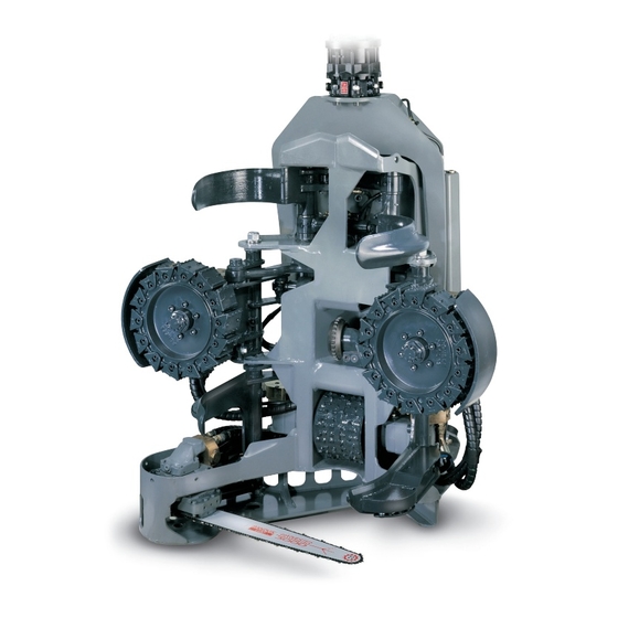
- Page 5 H73001 Technical data S e r v i c e t r a i n i n g Chain lubricating oil container Saw motor Saw bar Rotator Feed rollers Serial number Reaction bar (Give the serial number when Delimbing knives (front) ordering spare parts or otherwise Delimbing knife cylinder (front) contacting the manufacturer)
- Page 6 0-4 m/s Delimbing unit: One fixed ond four movable knives. Delimbing diameter 670 mm Delimbing knives and feed rollers separately controllable Measuring and control automation: PONSSE 1000 or PONSSE OPTI system Automatic volume measurement with data storage and printer output. 28022000...
-
Page 7: Electrical Equipment
S e r v i c e t r a i n i n g Electrical equipment Electrical harness / sensoring Harvester connector Valve connectors Saw sensor Length measure sensor Diameter sensor Tilt sensor Colour marking connectors 28022000... - Page 8 S e r v i c e t r a i n i n g Electrical equipment Optinet To pivot frame Computer To crane 02052000...
- Page 9 S e r v i c e t r a i n i n g Electric diagram (IPS) Directional valve Location number of pin connector box solenoids+diodes Saw rotation Saw feed Slow forward Slow reverse Rollers open Front knives open Fast forward Fast reverse brown...
- Page 10 S e r v i c e t r a i n i n g Electric diagram, Knutsson Location number of pin connector box Directional valve solenoids+diodes Saw rotation Saw feed Slow forward Slow reverse Rollers open Front knives open Fast forward Fast reverse Lubrication oil pump...
- Page 11 S e r v i c e t r a i n i n g Adjustment and service instructions Length measuring device Sensor casing Sensor Metering Rubber wheel coupling 29022000...
- Page 12 S e r v i c e t r a i n i n g Adjustment and service instructions Length measuring device Testing the length measurement Lift the harvester head so that you can rotate the measuring roller. Shut the engine off. Turn on the measurement system, switch on the power to the harvester head by pulling the knob out on the main switch (moto-switch).
- Page 13 S e r v i c e t r a i n i n g Adjustment and service instructions Diameter measuring Before calibrating of the diameter, you should check the following: The tree travels in the centre of the harvester head. If necessary, adjust the tree (a round one) to the centre using the reaction brace .
- Page 14 S e r v i c e t r a i n i n g Adjustment and service instructions Saw sensor replacement 1 mm Turn the engine off and make sure no one is able to start the machine. Turn the saw bar to its upper position and remove the old sensors.
- Page 15 S e r v i c e t r a i n i n g Adjustment and service instructions Saw sensor replacement Adjustment of sensors Sensors Adjustment plate 29022000...
- Page 16 S e r v i c e t r a i n i n g Adjustment and service instructions, saw Adjustment of sensors Saw bar limit screw 29022000...
- Page 17 S e r v i c e t r a i n i n g Adjustment and service instructions Delimbing knife sharpening The condition of the delimbing knives has a major effect on the pruning result and pruning resistance (especially in the summer). The recommended shape of the delimbing knives is shown in the °...
- Page 18 S e r v i c e t r a i n i n g Testing instructions Pulse sensor testing 1. Turn on the power by turning the switch to the ON position. 2. Switch the NPN/PNP switch to the correct position, depending on which type of inductive sensor you are going to test.
- Page 19 S e r v i c e t r a i n i n g Testing instructions Using a digital multimeter Resistance measurement NOTE! The measured object has to be without a voltage. E.g., Checking the diameter sensor: 1. Connect the wires as in the adjacent figure. 10.0 2.
- Page 20 S e r v i c e t r a i n i n g Testing instructions Using a digital multimeter Voltage measurement NOTE! AC/DC switch in position DC Connect the black measuring cable to the COM terminal and the frame of the machine. Connect the red measuring cable to the V terminal and the 24.0 other end to the wire or connector you want to...
- Page 21 S e r v i c e t r a i n i n g Feed hydraulics Restrictors Feed valve (fast) Feed valve (slow) Feed pressure relief valve Restrictor 29022000...
- Page 22 S e r v i c e t r a i n i n g Saw rotation hydraulics valve Saw motor Anticavitation valve Casing line check valve 29022000...
- Page 23 S e r v i c e t r a i n i n g Saw motor hydraulics Cooling option Tank line Resistor check valve 29022000...
- Page 24 S e r v i c e t r a i n i n g Saw rotation hydraulics F12-30 Casing line check valve Restrictor Main spindle Pilot -operated valve F12-30 Anticavitation valve 29022000...
- Page 25 S e r v i c e t r a i n i n g Saw feed hydraulics Directional valve Pressure reducer T-line check valve Resistor check valve Saw cylinder 29022000...
- Page 26 S e r v i c e t r a i n i n g Lubrication pump Screen + check valve Check valve Lubrication oil pump 29022000...
- Page 27 S e r v i c e t r a i n i n g Lubrication pump Opti oil control Lubrication pump Directional valve Lubrication pump valve From measuring Adapter block device T-line check valve Pressure reducer 29022000...
- Page 28 Hydraulic diagram H73001-H73202 S e r v i c e t r a i n i n g 2-power, F11-19 Feed (fast) Feed (slow) Rear knives Feed rollers Saw feed Front knives Tilting Rotator pressing Saw feed 20032000...
- Page 29 Hydraulic diagram H73203 S e r v i c e t r a i n i n g 1-power, F11-19 Feed (fast) Feed (slow) Rear knives Feed rollers Saw feed Front knives Tilting Rotator pressing Saw feed 20032000...
- Page 30 Hydraulic diagram H73203 S e r v i c e t r a i n i n g 1-power, cooling, F11-19 Feed (fast) Feed (slow) Rear knives Feed rollers Saw feed Front knives Tilting Rotator pressing Saw feed 6.10 20032000...
- Page 31 Hydraulic diagram H73211 S e r v i c e t r a i n i n g 1-power, F12-30 Feed (fast) Feed (slow) Rear knives Feed rollers Saw feed Front knives Tilting Rotator pressing Saw feed 6.11 20032000...
- Page 32 Hydraulic diagram S e r v i c e t r a i n i n g Excavator, 1-power Feed (fast) Feed (slow) Rear knives Feed rollers Saw feed Front knives Tilting Rotator pressing Saw feed 6.12 20032000...
- Page 33 S e r v i c e t r a i n i n g Pressure adjustments A. SAW (rotate) 10. Saw check valve B. SAW (feed) 11. Saw pressure reducer valve C. TRUNK FEED ROLLERS 12. Saw direction valve D.
- Page 34 S e r v i c e t r a i n i n g Pressure adjustments Harvester head pressure relief valve adjustment THE PRESSURE OF THE BASE MACHINE MUST BE ADJUSTED BEFORE THE FOLLOWING ADJUSTMENTS ARE MADE. The measurement connector is on the opposite side of the pressure reducing valve.
- Page 35 S e r v i c e t r a i n i n g Pressure adjustments Saw cylinder feed pressure Disconnect the electric cable from the harvester head. Connect a pressure gauge to the measurement connector. Start the engine and set the constant pressure: - engage the working brake and constant rpms - turn on the harvester head main switch Open the lock and adjust the pressure reducer valve by turning...
- Page 36 S e r v i c e t r a i n i n g Pressure adjustments Feed roller cylinder pinch pressure NOTE! BE ESPECIALLY CAREFUL NOT TO ADJUST THE PINCH PRESSURE TOO HIGH. Disconnect the electric cable from the harvester head. Connect a pressure gauge to measurement connector.
- Page 37 S e r v i c e t r a i n i n g Pressure adjustments Front delimbing knife cylinder pressure adjustment Disconnect the electric cable from the harvester head. Connect a pressure gauge to the measurement connector. Start the engine and set the constant pressure: - engage the working brake and constant rpms - turn on the harvester head main switch Open the lock and adjust the pressure reducer valve by turning adjustment...
- Page 38 S e r v i c e t r a i n i n g Pressure adjustments Rear delimbing knife cylinder pressure adjustment Disconnect the electric cable from the harvester head. Connect a pressure gauge to the measurement connector. Start the engine and set the constant pressure: - engage the working brake and constant rpms - turn on the harvester head main switch Open the lock and adjust the pressure reducer valve by turning adjustment...
- Page 39 S e r v i c e t r a i n i n g Pressure adjustments Harvester head tilt cylinder pressure adjustment (tilt) Disconnect the electric cable from harvester head. Tilt the harvester head to a horizontal position. Connect a pressure gauge to the measurement connector. Start the engine and set the constant pressure: - engage the working brake and constant rpms - turn on the harvester head main switch...
- Page 40 S e r v i c e t r a i n i n g Pressure adjustments Rotator pressure relief valve adjustment (Indexator) ATTENTION! MAKE SURE THAT YOUR HELPER IS FAMILIAR WITH THE MACHINE AND KNOWS HOW TO OPERATE IT. Disconnect the rotator hoses and connect pressure gauges to them.
- Page 41 S e r v i c e t r a i n i n g Extra equipments Color marking device Crane Shut-off cock Electric valve Nozzles 22032000...
- Page 42 S e r v i c e t r a i n i n g Extra equipments Stump treatment system Electric valve Crane boom head 22032000...
- Page 43 Pressure reducer valve of saw feed Pressure relief valve of front knives Pressure reducer valve of front knives Pressure reducer valve of rear knives (H53, H73) Pressure relief valve of rear knives (H53, H73) Tilt cylinder pressure of multi-function unit...
Need help?
Do you have a question about the H73 and is the answer not in the manual?
Questions and answers
How do you calibrate dia
To calibrate the diameter on a PONSSE H73:
1. Ensure the tree travels in the center of the harvester head. If needed, adjust it using the reaction brace.
2. Check that measurements A and B are equal. If the difference is greater than 5 mm, adjust the reaction brace. A half revolution changes the difference by 5 mm. Recheck the measurements.
3. When the feeding rollers are closed, the sensor reading must be 30. If not, adjust it by turning the sensor body.
This answer is automatically generated