Table of Contents
Advertisement
Quick Links
Advertisement
Table of Contents

Related Manuals for Hamilton Jet HJ212

Summary of Contents for Hamilton Jet HJ212
- Page 1 Installation and Service Manual HJ212 Jet unit Manual R3A3...
- Page 2 C.W.F. Hamilton & Co Ltd. Due to our policy of continuous development, specifications in this document are subject to change without notice or obligation. Jet or control type HJ212 Part number 089212 Revision...
-
Page 3: Table Of Contents
Contents 1 - Introduction _______________________________________________________ 1-1 Limited Warranty _________________________________________________________ 1-1 Warranty and Ownership Registration Form ___________________________________ 1-3 General Safety Notice _____________________________________________________ 1-4 2 - Product Description ______________________________________________ 2-1 Introduction _____________________________________________________________ 2-1 Equipment Description ____________________________________________________ 2-2 Main Components __________________________________________________ 2-3 3 - Design Basics ______________________________________________________ 3-1 Propulsion System Design __________________________________________________ 3-1 Hull Design ________________________________________________________ 3-1 Drive Lines ______________________________________________________________ 3-4... - Page 4 Engine mounting ___________________________________________________ 3-10 Engine systems ____________________________________________________ 3-10 Exhaust systems ___________________________________________________ 3-11 Governor settings __________________________________________________ 3-11 Dry run kit (optional extra) ________________________________________________ 3-12 Scope of use ______________________________________________________ 3-12 4 - Precautions Against Corrosion _________________________________ 4-1 General _________________________________________________________________ 4-1 Electrical Wiring System ______________________________________________ 4-1 D.C.
- Page 5 Fixing the Intake Block to the Hull ______________________________________ 5-2 Transom Preparation ________________________________________________ 5-2 Equipment Preparation ____________________________________________________ 5-3 Steering Components ________________________________________________ 5-3 Reverse Components ________________________________________________ 5-3 Mounting the Jet Unit _____________________________________________________ 5-3 Preparation ________________________________________________________ 5-3 Mounting the Jet Unit ________________________________________________ 5-4 Fix the Transom Plate to the Hull _______________________________________ 5-4 Installation Checks for the Jet Unit _____________________________________ 5-4 Final Assembly _____________________________________________________ 5-6...
- Page 6 7 - Fault Finding _______________________________________________________ 7-1 System Faults ____________________________________________________________ 7-1 Jet Unit Faults ____________________________________________________________ 7-1 Engine RPM increases suddenly ________________________________________ 7-1 Engine RPM decreases _______________________________________________ 7-1 Water leaking from under the bearing housing ___________________________ 7-2 Loud high pitched rattling whine _______________________________________ 7-2 Excessive vibrations, gradually increasing ________________________________ 7-2 Engine RPM increases gradually over a period of time ______________________ 7-2 Sudden increase in vibration from the jet unit ____________________________ 7-2...
- Page 7 Jet Unit Servicing Details __________________________________________________ 8-10 Internal Water Path: ________________________________________________ 8-10 Thrust Bearing _____________________________________________________ 8-11 Water Seal: _______________________________________________________ 8-11 Anodes: __________________________________________________________ 8-11 Steering System ___________________________________________________ 8-12 Reverse Shaft and Bushes____________________________________________ 8-13 Reverse Linkages: __________________________________________________ 8-13 H Bar or Driveshaft Universal Joints ____________________________________ 8-13 Engine Alignment: __________________________________________________ 8-13 Jet Unit ________________________________________________________________ 8-13 Impeller blades: ___________________________________________________ 8-13...
- Page 8 Reverse Assembly Overhaul ________________________________________________ 9-6 Reverse Duct Removal _______________________________________________ 9-6 Reverse Duct Overhaul _______________________________________________ 9-6 Reverse Link Removal and Inspection ___________________________________ 9-7 Bush and O-Ring Replacement _________________________________________ 9-7 Reverse Shaft Shouldered Bush Replacement _____________________________ 9-8 Latch System Removal and Overhaul ____________________________________ 9-8 Latch System Checking for Wear _______________________________________ 9-9 Reverse Assembly Refitting ___________________________________________ 9-9 Steering Assembly Overhaul _______________________________________________ 9-12...
- Page 9 Transom Plate Assembly Overhaul __________________________________________ 9-31 Transom Plate Removal _____________________________________________ 9-31 Transom Plate Refitting _____________________________________________ 9-32 Intake Screen ___________________________________________________________ 9-32 Intake Screen Removal ______________________________________________ 9-32 Intake Screen Refitting ______________________________________________ 9-32 Hatch Extension _________________________________________________________ 9-33 Hatch Extension Fitting ______________________________________________ 9-33 Hatch Extension Removal ____________________________________________ 9-34 10 - Appendix _______________________________________________________ 10-1 Conversions ____________________________________________________________ 10-2 Loctite Application Guide __________________________________________________ 10-3...
- Page 10 Stud Installation __________________________________________________ 10-30 Set Screws _______________________________________________________ 10-30 Hydraulic Cylinder Piston ___________________________________________ 10-31 Hydraulic Fittings _________________________________________________ 10-31 Thread Lubricants _________________________________________________ 10-33 Recommendations for Lubricants and Oils ___________________________________ 10-34 Hydraulic Fluids ___________________________________________________ 10-34 Bearing Housing Lubrication ________________________________________ 10-36 Joint Lubrication __________________________________________________ 10-37 Drivers Guide __________________________________________________________ 10-38 Starting Up ______________________________________________________ 10-38 Ahead, Zero Speed and Astern Controls _______________________________ 10-39...
-
Page 11: Introduction
To the extent permitted by law, this warranty sets out the original purchaser's exclusive remedies with respect to the product covered by this warranty. In the event that Hamilton Jet determines it is unable to repair or replace any component part(s) found to be defective in materials and/or workmanship,... - Page 12 Designer's Manual. This warranty will not extend to the product unless a negative earth bonding system has been installed in the vessel as specified in the respective Hamilton Jet Product Manual, and a Jet Mainshaft critical speed check carried out to Hamilton Jet's written satisfaction.
-
Page 13: Warranty And Ownership Registration Form
Email, marketing@hamjet.co.nz Hamilton Jet encourages the distributor to take responsibility for ensuring the purchaser and the distributor complete this form at the time of sale and return it to Hamilton Jet. Please complete one form per vessel only. Jet Model... -
Page 14: General Safety Notice
Introduction Installation and Service Manual General Safety Notice Warning A warning is an operation or maintenance procedure, practice, condition or statement which, if not strictly observed, could result in injury or death to personnel. This is indicated throughout this manual as shown below: Caution: A caution is an operation or maintenance procedure, practice condition or statement which, if not strictly observed, could result in damage to, or destruction of equipment or loss of mission effectiveness. -
Page 15: Product Description
Safety for personal working in the water near the vessel. The waterjet unit is an ideal form of propulsion for vessels working in a marine mammal environment. Hamilton Jet pioneered the commercial development of the modern waterjet system in the early 1950’s. -
Page 16: Equipment Description
Hamilton Jet is dedicated to the production of the highest quality waterjets and controls systems designed and manufactured to meet the requirements of the worlds leading certifying authorities. -
Page 17: Main Components
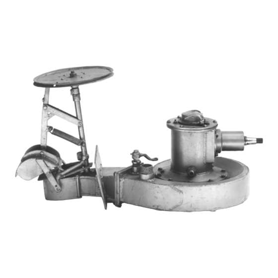
Product Description Installation and Service Manual Main Components Intake block Is bolted or welded to the vessel hull. Intake Is bolted to the intake block and represents the main structural body of the jet unit. It is capable of transmitting the full thrust of the jet unit to the hull bottom. The intake is cast from high silicon aluminium alloy. - Page 18 Product Description Installation and Service Manual Steering assembly Attached to the rear of the tailpipe, consists of a nozzle housing, nozzle insert and steering nozzle. The steering nozzle is mounted inside the nozzle housing on vertical pivot pins and is rotated to port or starboard by linkages attached to an inboard steering tiller.
- Page 19 Product Description Installation and Service Manual Figure 2: Figure 1: HJ212 Main Components Intake Reverse duct Intake block Transom plate Inspection hatch Anode Reverse assembly Intake screen ( hidden) Steering shaft Hatch extension Tail pipe...
- Page 20 Product Description Installation and Service Manual...
-
Page 21: Design Basics
Design Basics Installation and Service Manual 3 - Design Basics In This Section Propulsion System Design ..................... 3-1 Drive Lines ..........................3-4 Universal Driveshaft Alignment ..................... 3-5 Jet Mainshaft Alignment ....................... 3-8 Water Offtake ........................3-9 Engine Location and Mounting ....................3-10 Dry run kit (optional extra) .................... - Page 22 Design Basics Installation and Service Manual Mono hull design Figure 3: Mono Hull Design Strakes inside width of intake should stop 0.5meters aft of dynamic air/water interface Shaded area should be kept free of any appendages including water pickups Air/water interface Strake Jet unit intake Multi hulled vessels...
- Page 23 The following diagram shows the maximum size and position of the trim tab that may be located under the jet unit. Contact Hamilton Jet if further details are required. Figure 5: Allowable Trim Tab Location Maximum size of trim tab...
-
Page 24: Drive Lines
Due to certain engine components fouling on the jet unit intake, the 454 Chev Mercruiser engine cannot be mated to the HJ212 jet unit using a Centaflex coupling. C.W.F Hamilton & Co Ltd recommend the use of a H-bar type coupling in preference to the Centa coupling arrangement for the 454 Chev Mercruiser engine. -
Page 25: Engineering Checks
Depending on the distance between the jet unit coupling flange and the engine, other driveline options may be chosen. Longer drivelines would not normally be used on this jet. If they are under consideration, consult Hamilton Jet whilst using the following sections as a guide. Double universal fixed length driveshaft (Cardan shaft): This is the usual type of driveshaft used. -
Page 26: Jet Coupling Flange Details
Design Basics Installation and Service Manual Figure 6: 'W' Configuration Driveshaft Jet coupling flange Jet mainshaft axis Engine / gearbox flange θ and θ must be equal If X1 = X2 and both input and output axis meet at point P, then θ = θ... -
Page 27: Moments Of Inertia
The moment of inertia data for the jet unit is provided so that a torsional vibration analysis can be done. Mainshaft Dimensions Figure 8: Mainshaft Dimensions Mainshaft Coupling Impeller Thrust bearing Marine bearing Impeller centre of gravity HJ212 mainshaft dimensions Item Type Mass (kg) Polar Mol (kg.m²) Mainshaft Ø38.1 0.0012 Coupling Ø97... -
Page 28: Critical Speed Of Mainshaft
Design Basics Installation and Service Manual Critical Speed of Mainshaft C.W.F. Hamilton & Co. Ltd. must be consulted when calculating the critical speed of the jet unit mainshaft. The heavier splined end of the universal driveshaft should be fitted towards the engine. If a heavy driveline is used then a transverse vibrational analysis of the jet unit mainshaft should also be done. -
Page 29: Water Offtake
Design Basics Installation and Service Manual Hull deadrise angle Mainshaft angle relative to keel B1 (shaft angle in plan view) B2 (shaft slope in elevation) 0° 0.0° 5.0° 5° 0.4° 5.0° 10° 0.9° 4.9° 15° 1.3° 4.8° 20° 1.7° 4.7° 25°... -
Page 30: Engine Location And Mounting
Design Basics Installation and Service Manual Engine Location and Mounting Engines should be positioned to give the craft the most suitable fore and aft trim for the proposed boat speed. For semi-planing and moderate planing speed craft, the engine(s) should be positioned well forward towards amidships for best trim and speed. -
Page 31: Exhaust Systems
Design Basics Installation and Service Manual Exhaust systems Engine exhausts should not be located below the waterline near the jet units. Engine exhausts should be sited above the waterline. Water containing exhaust gasses can enter the jet unit when moving astern causing loss of thrust and control. -
Page 32: Dry Run Kit (Optional Extra)
Design Basics Installation and Service Manual Dry run kit (optional extra) The dry run kit is an optional extra that can be fitted to the jet unit at the customer's request. It is purchased at additional cost and should be requested when the initial jet order is placed. The dry run system is typically used for man-overboard boats and lifeboats where the engines need to be started before the vessel is in the water. -
Page 33: Precautions Against Corrosion
Refer to drawing: 85114 Earth Bonding System. Refer to drawing: HM00013001 Corrosion Monitor. Prevention of Corrosion Vessels using Hamilton jet units must be bonded and wired as described in this section. Electrical Wiring System The guidance of local inspecting authority rules must always be sought. -
Page 34: D.c. Systems
Precautions Against Corrosion Installation and Service Manual D.C. Systems The DC system should use two insulated "normally conducting" wires, a positive and a negative. The negative must not run through the frame of any unit, through the hull of the boat, or through the bonding system. -
Page 35: Using A Galvanic Isolator
Precautions Against Corrosion Installation and Service Manual Using a Galvanic Isolator Alternatively with AC shore supply, a galvanic isolator can be installed on the AC earth wire just after the shore power inlet. This isolates the vessel from low voltage D.C. galvanic currents, while allowing any short circuit to be safely conducted back to shore. -
Page 36: Corrosion Monitor
Precautions Against Corrosion Installation and Service Manual Corrosion Monitor It is recommended that a high impedance corrosion monitor be fitted. There must be no possibility of an electrical connection between the jet units and the ships batteries. If the jet units are isolated from the hull, corrosion monitoring of each jet unit external wetted surface and internal intake duct should be carried out. -
Page 37: Anodes
Precautions Against Corrosion Installation and Service Manual Anodes The anodes fitted to the jet unit are made from aluminium alloy to MIL-A-24779 (SH) or zinc alloy to MIL- 18001H. Do not paint over the anodes as this will prevent their correct operation. If corroding, the anodes are providing protection and should be inspected regularly and replaced when 2/3 corroded. -
Page 38: Impressed Current Protection
Precautions Against Corrosion Installation and Service Manual Impressed Current Protection Impressed current protection may be used if desired. Follow the supplier's instructions. Impressed current systems should have a "fail safe" feature which prevents the potential falling below -1100mV referenced to a silver / silver chloride reference electrode. -
Page 39: Installation
Installation Installation and Service Manual 5 - Installation In This Section Hull Preparation........................5-2 Equipment Preparation ......................5-3 Mounting the Jet Unit ......................5-3 Installation of Control Equipment ..................5-10 Steering Installation ....................... 5-13 Make sure that the engine cooling water pick up is not directly ahead of the jet unit intake, but well to the side to avoid turbulent water flow into the jet unit. -
Page 40: Hull Preparation
Installation Installation and Service Manual Hull Preparation In multiple jet installations, the jet units may be configured for either port, starboard or centre mounting. Make sure that each jet is installed in the correct position as shown on the installation drawing. Fixing the Intake Block to the Hull For GRP hulls If possible, the intake block should be mounted in the hull mould before moulding. -
Page 41: Equipment Preparation
Installation Installation and Service Manual Equipment Preparation Do not unpack the jet unit until it is required for installation. This will prevent mechanical damage and entry of foreign matter into the jet. Unpack carefully to prevent damage and loss of small items. Steering Components The jet unit is shipped complete with the steering components attached and should not need to be removed. -
Page 42: Mounting The Jet Unit
Installation Installation and Service Manual Mounting the Jet Unit Lift the jet unit away from the intake block Screw in and tighten the studs [3] provided into the tapped holes in the intake block. To fit the studs, tighten two nuts together on the top of the stud and use a spanner to screw the stud into the intake block. - Page 43 Installation Installation and Service Manual Jet unit mounting Check the following: Check that the intake block is faired to the hull bottom. Contours should be smooth with no steps or protrusions greater than 2mm. There are no flow obstructions forward of the intake block. Refer to figure: Mono hull design on page 3- ...
-
Page 44: Final Assembly
Due to certain engine components fouling on the jet unit intake, the 454 Chev Mercruiser engine cannot be mated to the HJ212 jet unit using a Centaflex coupling. C.W.F Hamilton & Co Ltd recommend the use of a H-bar type coupling in preference to the Centa coupling arrangement for the 454 Chev Mercruiser engine. - Page 45 Installation Installation and Service Manual Mounting the engine with the close coupling kit: Close Coupling Engine Mount For this option, the rear engine mount is on the jet unit. The jet and engine mount have been designed to take loads well in excess of the normal operating loads. Crash conditions, however, are unpredictable.
- Page 46 Installation Installation and Service Manual Mount the flywheel adapter plate onto the flywheel and check that the bore is running true to within 0.1 TIR. Tighten the securing bolts to the approved torque. Refer to drawing: HJ21202002 Flywheel Adaptor. Mount the Centa coupling on to the flywheel adapter plate and tighten the bolts to the recommended ...
- Page 47 Installation Installation and Service Manual H-bar driveline option Refer to drawing: HJ21202004 H-Bar Drive Coupling This option allows the engine to be mounted well back in the boat, with the engine mounted conventionally on its own 4 mounts. It has the advantage that the driveline is accessible and can be removed readily. This option can be used with engines that do not match the close coupling kit components.
-
Page 48: Engine Cooling
Installation Installation and Service Manual Engine Cooling Ensure that the engine cooling water pick up is not directly ahead of the jet unit intake, but well to the side to avoid turbulent water flow into the jet. The engine may be cooled conventionally or by making use of the inboard water offtake for the jet. The jet is supplied with the water offtake plugged with a hosetail connection. -
Page 49: Reverse Latch Assembly
Installation Installation and Service Manual Reverse Latch Assembly The latch locks the reverse duct in any position. The reverse duct can be moved by the hand controller from inside the vessel, but cannot be moved by forcing the reverse duct itself. The latch has been factory adjusted and tested and should not require adjustment during installation. -
Page 50: Zero Speed Detent
Installation Installation and Service Manual Zero Speed Detent Refer to drawing: HJ21207003 Reverse Assembly. A detent is provided to indicate the zero speed position at the control lever. Zero speed detent Unlike conventional propulsion systems using gearboxes, the waterjet does not have a positive neutral, instead relying on the position of the reverse duct to provide neutral (zero speed). -
Page 51: Steering Installation
Installation Installation and Service Manual Steering Installation Refer to drawing: HJ21206000 Steering Assembly. Good steering is of very important on high speed jet boats. This jet, with a steerable nozzle, has a particularly powerful and positive steering effect. The steering system on the HJ-212 jet unit is balanced so that power assisted steering is not necessary. Steering Wheel Number of Turns Steering is normally operated from the helm by a steering wheel, although a tiller is sometimes used. -
Page 52: Cable Pulley System
Refer to drawing: CTHLM 06001 Steering Wheel Cable Operated. This is a steering option and is not standard for the HJ212 jet unit. If choosing a push-pull cable, use a heavy duty rotary system or a rack and pinion system such as those tabulated below. -
Page 53: Commissioning
Commissioning Installation and Service Manual 6 - Commissioning In This Section Pre-Launch Checks ......................... 6-1 Post Launch Checks ....................... 6-2 Engine Running Checks (Vessel Moored) ................6-2 Vessel Speed and Handling Trials ..................6-2 After Initial Trials (After Engine Shutdown) ................6-3 This information is intended for use by CWF Hamilton representatives. -
Page 54: Post Launch Checks
Commissioning Installation and Service Manual Post Launch Checks Before starting the engines, check the following: There are no water leaks: At the transom seal. At the intake base. Visually check for water leaks from under the bearing housing ... -
Page 55: Vessel Speed And Handling Trials
Commissioning Installation and Service Manual Vessel Speed and Handling Trials A Hamilton distributor should be present to observe, record and verify results. If a problem is detected, immediately return at reduced power, to the mooring. DO NOT operate the jet unit until the fault has been repaired. Leave the mooring and check that the steering is working correctly at Forward, Zero Speed and Astern. - Page 56 Commissioning Installation and Service Manual...
-
Page 57: Fault Finding
Fault Finding Installation and Service Manual 7 - Fault Finding In This Section System Faults ......................... 7-1 Jet Unit Faults ........................7-1 Dry run faults ......................... 7-3 Reverse System Faults ......................7-3 Steering System Faults ......................7-5 System Faults The following pages contain solutions to faults that could occur and some possible solutions: Locate a symptom similar to that experienced. -
Page 58: Water Leaking From Under The Bearing Housing
Fault Finding Installation and Service Manual Water leaking from under the bearing housing Possible cause Solution Faulty water seal Inspect and replace the water seal Refer to section: Bearing Housing and Water Seal Assembly Dismantling on page 9-18. Loud high pitched rattling whine Possible cause Solution Blockage in the jet unit... -
Page 59: Low Engine Rpm
Fault Finding Installation and Service Manual Low engine RPM Possible cause Solution Problem with engine Investigate engine operation Incorrect impeller and nozzle insert selection Contact C.W.F.Hamilton Ltd Refer: Engine Manufacturer's manual Refer to drawing: HJ21203001 Impellers Thrust bearing excessively hot Possible cause Solution Thrust bearing failure... -
Page 60: Reverse System Faults
Fault Finding Installation and Service Manual Reverse System Faults Reverse duct will not move Possible cause Solution Physical obstruction of reverse duct Remove obstruction Reverse duct creeping down from the up position Possible cause Solution Reverse latch faulty Adjust nuts Refer to drawing: HJ21207003 Reverse Assembly. -
Page 61: Steering System Faults
Fault Finding Installation and Service Manual Steering System Faults Steering nozzle slow to respond Possible cause Solution Grit jamming nozzle. Move nozzle from side to side to release grit. Flush nozzle with water. Remove nozzle from nozzle housing and check spacers and washers for wear and damage. - Page 62 Fault Finding Installation and Service Manual...
-
Page 63: Maintenance
Maintenance Installation and Service Manual 8 - Maintenance General The jet unit requires regular servicing as detailed in the following sections. Vessel usage is assumed to be 1000 operational hours per year. The frequency of the following service items may be varied to suit actual operating conditions. The overhaul section of this manual provides removal and refitting instructions for the various jet unit components. -
Page 64: Salt Water Operation
Salt Water Operation The HJ212 jet unit is designed as a trailered craft and is not intended to be moored in the sea. It can be used freely in the sea, but the vessel should be slipped or trailered and flushed with fresh water or given a short run in fresh water before storage. -
Page 65: Maintenance Of Waterjet Coatings
Maintenance Installation and Service Manual Re-application of Antifoul over existing Antifoul Trilux antifoul may be applied directly over old Trilux in good condition. This can be done after thorough cleaning/degreasing and light abrading of the old Trilux. Abrasive hand pads (Scotch-Brite) or wet sanding is an acceptable way of abrading the old Trilux. - Page 66 Maintenance Installation and Service Manual In October 2012 the grey gloss was changed from a polyester urethane based technology to a polysiloxane technology. The two products are not interchangeable and cannot be applied over each other. Refer to Product Bulletin PRB_08_2012 for details. Any recoating or repair of the International Paints factory applied systems must be done with compatible products.
- Page 67 Maintenance Installation and Service Manual Bare metal refurbishment - aluminium The aluminium castings used in the manufacture of Hamilton jets require special attention when the coating has been damaged down to bare metal. The surface needs to be very clean and freshly abraded prior to the application of a suitable primer coating to ensure a good bond is achieved.
- Page 68 Maintenance Installation and Service Manual Bare metal refurbishment - steel and stainless steel The area of refurbishment and immediate surroundings should be degreased with a water soluble degreaser and thoroughly rinsed off with clean water. Abrasive blast the surface clean to achieve a finish to Sa 2.5 (or to equivalents - AS1627.4 Class 2.5, NACE 2, SSPC –...
-
Page 69: Preservation (Pre Installation)
Maintenance Installation and Service Manual Application of Grey Gloss over existing Grey Gloss The grey gloss top coat is based on polysiloxane technology. When applying grey gloss over existing grey gloss (in sound condition), the existing paint requires abrading to provide a key for the new coating. A tie coat is not used, as an epoxy tie coat is not recommended on a polysiloxane coating. -
Page 70: Preservation (Post Installation)
Maintenance Installation and Service Manual Preservation (Post Installation) Do not run the jet unit out of the water unless it is fitted with a dry run kit or forced water lubrication system. When the vessel is not operational for an extended period, the following procedures must be followed to prevent marine growth and corrosion problems. -
Page 71: Hj Jet Unit Service Intervals
Maintenance Installation and Service Manual HJ Jet Unit Service Intervals Item Actions Refer to section: Internal water Clear blockages Internal Water Path: on page 8-10 path Thrust bearing Lubricate Thrust Bearing on page 8-11 Water seal Check for leaks Water Seal: on page 8-11 Anodes Check condition Anodes: on page 8-11... -
Page 72: Daily "Pre Use" Servicing Checks
Maintenance Installation and Service Manual Daily "pre use" servicing checks The following areas should be checked on a daily basis if the vessel is in regular use. Intake screen, impeller, stator blades: Ensure that the water level is below the level of the inspection cover or overflow preventer before ... -
Page 73: Thrust Bearing
Maintenance Installation and Service Manual Thrust Bearing Every 30 hours (or monthly whichever comes first). Grease with a good quality lithium based ball bearing grease. Normal operating temperature is 50 - 55 º C (120 - 130 º F) but the bearing can operate up to 120 ºC. ... -
Page 74: Steering System
Maintenance Installation and Service Manual Steering System Daily Check integrity. Monthly A thorough check of the whole steering system. Refer to section: Checking the steering system on page 8-15 Steering cotter pins Daily: Check the condition of the cotter pins. ... -
Page 75: Reverse Shaft And Bushes
Maintenance Installation and Service Manual Reverse Shaft and Bushes Every 3 months: Check play in reverse shaft and bushes for excessive lateral play, wear or binding. Check for signs of leaking around the seal. Replace bush or seal as required. ... -
Page 76: Impeller Check For Wear And Damage
Maintenance Installation and Service Manual Impeller check for wear and damage: Look for corrosion and damage on all surfaces. Check the impeller leading and trailing edges for damage or wear. Marine bearing: Check the marine bearing for scoring or localized wear. Replace if worn or damaged. To check the bearing for wear: Push the mainshaft hard from side to side. -
Page 77: Excessive Wear
Maintenance Installation and Service Manual Anti fouling Paints Do not apply copper oxide based anti-fouling paints. Do not paint over the anodes. Anti-Seize Compounds Do not use anti-seize compounds which are based on graphite, nickel or copper flakes - these will cause corrosion. Anti-seize compounds, usually containing zinc flakes, are available for aluminium. - Page 78 Checking the steering Refer to drawing: HJ21206000 Steering Assembly. The HJ212 jet steering nozzle system has been designed with minimal clearance between the nozzle and the nozzle housing. This gives optimum steering thrust at any lock. It is important to keep the pivot bushes and pins in good condition to maintain this clearance.
-
Page 79: Checking The Reverse Linkages
Maintenance Installation and Service Manual If a severe jam-up or impact has occurred, all parts of the steering system should be examined for damage. This should include the remote system and the following items on the jet unit. Steering shaft: ... -
Page 80: Laying Up
The HJ212 jet is not designed to be moored in salt water for more than a few days. Do not run the jet unit out of the water unless it is fitted with a dry run kit or forced water lubrication system. -
Page 81: Threaded Fasteners
Maintenance Installation and Service Manual Threaded Fasteners Refer to section: Tightening Torques on page 10-28. Tightening Torques Ensure all threaded fasteners are tightened to the correct torque as shown in the appendix and any relevant assembly drawing. Thread locking agents Some fasteners require thread locking agents to prevent loosening. - Page 82 Maintenance Installation and Service Manual 8-20...
-
Page 83: Overhaul
Overhaul Installation and Service Manual 9 - Overhaul In This Section General Information ......................9-1 Reverse Assembly Overhaul ....................9-6 Steering Assembly Overhaul ....................9-12 Bearing Housing Assembly overhaul ..................9-18 Tailpipe Area Overhaul ......................9-22 Tailpipe Area Dismantling ...................... 9-22 Tailpipe, Marine Bearing and Wear Ring Inspection ............. -
Page 84: General Information
Overhaul Installation and Service Manual General Information Inspection Covers Extreme care is required whenever inspection covers are removed, as water may enter the vessel through these openings. Inspection cover nuts should not be fully removed until the inspection cover has been loosened, so that if the water level is higher than expected, the inspection cover can be re- secured. -
Page 85: Introduction
Salt water operation: The HJ212 jet unit is designed as a trailered craft and is not intended to be moored in the sea. It can be used freely in the sea, but the vessel should be slipped or trailered and flushed with fresh water or given a short run in fresh water before storage. -
Page 86: Care Of Jet Unit Paintwork
Overhaul Installation and Service Manual Care of Jet Unit Paintwork For detailed information on the jet unit paint work, Refer to section: Jet surface coating procedure on page 8- Anti fouling Paints Do not apply copper oxide based anti-fouling paints. Do not paint over the anodes. -
Page 87: Refitting The Locating Dowels
Overhaul Installation and Service Manual Using a multimeter, make sure that the electrical resistance between the anode and the mounting stud is less than 0.2Ω. If the anode is still in good condition: Make sure that it has not been painted over. The electrical resistance between the anode and the mounting stud is less than 0.2Ω. -
Page 88: Reverse Assembly Overhaul
Overhaul Installation and Service Manual Reverse Assembly Overhaul Refer to drawing: HJ21207003 Reverse Assembly. Reverse Duct Removal Remove the split pin [14] and the first of the 2 washers [60] securing the link actuator [21] to the reverse crank [11]. Remove the tension spring [18], if possible avoid removing the spring anchor bolt [6]. -
Page 89: Reverse Link Removal And Inspection
Overhaul Installation and Service Manual Reverse Link Removal and Inspection Remove the link actuator [21], link ball [22], link o-ring [38] and flat washer [24] from the port arm of the reverse duct by removing bolt [25]. If the tension spring [18] has not been disconnected, support the reverse duct [1] so as not to ... -
Page 90: Reverse Shaft Shouldered Bush Replacement
Overhaul Installation and Service Manual Reverse Shaft Shouldered Bush Replacement With the reverse shaft [8] removed from the jet unit, Press out the old bush using a suitable sized drift [10]. If the bush is hard to remove, apply light heat in the area of the bush to break the Loctite bond. -
Page 91: Latch System Checking For Wear
Overhaul Installation and Service Manual Latch System Checking for Wear Check the security of the bushes [42] in the chassis block [29]. Fit the brake rod [41] back through the bushes [42] and check for looseness, wear or stiffness in the ... - Page 92 Overhaul Installation and Service Manual Reverse shaft reassembly Lightly grease the reverse shaft and bushes [8, 9, 10]. Assemble the reverse spacer [28] and washers [31] in the correct order onto the reverse shaft [8]. From inside the vessel, fit the reverse shaft through seal [15] and bush [9]. Continue pushing the reverse ...
- Page 93 Overhaul Installation and Service Manual Latch assembly, installation and adjustment Assemble the latch release Refer to drawing: HJ21207003 Reverse Assembly. Install the reverse shaft [8] and crank [11] as shown in Section 9.3.1 Reverse Shaft Re-assembly. Fit the cable mount [20] onto the jet unit and secure with spring washers [49] and screws [50]. Torque ...
-
Page 94: Steering Assembly Overhaul
Overhaul Installation and Service Manual Adjust the latch release The latch should release after about 3mm of cable movement. As the brake plates [47] become worn in the central hole there is less cable movement before the latch releases. Eventually the latch will fail to lock at all. -
Page 95: Steering Nozzle Assembly Removal
Overhaul Installation and Service Manual Steering shaft bushes To replace the steering shaft bushes, carry out the following: Press out the old bush using a suitable sized drift [3]. Remove and discard o-ring [2] fitted to the forward end of the forward steering bush [3]. ... - Page 96 Overhaul Installation and Service Manual Inspect the steering nozzle Check the following components for wear or damage and repair or replace as necessary. Steering nozzle [16] Inspect the nozzle for any signs of damage including bending or cracking on the underside of the nozzle ...
-
Page 97: Steering Assembly Re-Fitting
Overhaul Installation and Service Manual Replace the nozzle housing flanged bush Make sure that the nozzle has been removed from the nozzle housing. Press out the old flanged bush using a suitable sized drift [10]. If the flanged bush is hard to remove, apply light heat in the area of the flanged bush to break the Loctite ®... - Page 98 Overhaul Installation and Service Manual Fit the nozzle to the nozzle housing Inspect the steering nozzle Before re-assembly, the nozzle should be examined for any sign of damage. In the case of a severe jam-up of the steering system, the nozzle arm may have become bent or cracked. If any cracks are found on the underside of the steering arm or if there is any sign of bending, the nozzle must be replaced.
- Page 99 Overhaul Installation and Service Manual Fit the nozzle housing to the tailpipe Apply Loctite 243 to studs [26] fitted to the tailpipe of the jet unit. Refer to drawing: HJ21201000 Base Jet Assembly. Refit the nozzle insert into the nozzle housing. ...
-
Page 100: Bearing Housing Assembly Overhaul
Overhaul Installation and Service Manual Bearing Housing Assembly overhaul Refer to drawing: HJ21201000 Base Jet Assembly Bearing Housing and Water Seal Assembly Dismantling Overhaul of the bearing housing and water seal with the vessel afloat is not recommended as water can enter the vessel through the intake opening. The water seal must be replaced if: If there have been signs of water leaking from underneath the bearing housing. -
Page 101: Inspect The Bearing Assembly And Water Seal
Overhaul Installation and Service Manual Water seal removal The water seal should not be removed unless it is being replaced. The water seal will not work correctly if it is removed and then reinstalled. The water seal need only be replaced if it is leaking, or there is insufficient material left to last to the next inspection. -
Page 102: Reassemble The Bearing Housing And Water Seal
Overhaul Installation and Service Manual Reassemble the Bearing Housing and Water Seal Refer to drawing: HJ21201000 Base Jet Assembly The water seal rubber bellows [4] will bind to the shaft [1] after about 15 minutes, so the assembly of the bearing should be completed within this time. Fit a new seal [6] to the bearing housing [8] and to the seal face holder [12]. - Page 103 Overhaul Installation and Service Manual Lightly grease the forward seal sleeve [5] and slide it onto the mainshaft up to the outer seal [6]. Press the forward seal sleeve [5] through the outer seal [6] until it is pressed firmly against the front of the bearing [7].
-
Page 104: Tailpipe Area Overhaul
Overhaul Installation and Service Manual Tailpipe Area Overhaul Remove the reverse duct and splash guard. Refer to section: Reverse Duct Removal on page 9-6. Disconnect the reverse shaft. Refer to section: on page 9-7. Disconnect the steering linkage. Refer to section: Steering System on page 8-12. ... -
Page 105: Tailpipe Area Dismantling
Overhaul Installation and Service Manual Tailpipe Area Dismantling Refer to drawing: HJ21201000 Base Jet Assembly. Remove the nuts [17] and spring washers [16] from the studs [30], securing the tailpipe to the intake. Remove the tailpipe [41] complete with the marine water bearing [2], off the studs [30] and slide the ... -
Page 106: Removal Of The Wear Ring And Insulator Strip
Overhaul Installation and Service Manual Removal of the wear ring and insulator strip Figure 11: Wear Ring Removal Intake Insulator Screw driver Wear ring Step A Find the joint in the wear ring. Step B Force a thin screw driver between the wear ring and the insulator, next to the joint. ... -
Page 107: Fitting A New Insulator
Overhaul Installation and Service Manual Fitting a new insulator Paint the inside of the impeller race with a thin layer of two pot vinyl etch primer suitable for aluminium and allow to dry (alternatively zinc phosphate may be used). Apply a thin coat of zinc phosphate epoxy primer suitable for aluminium (such as International Paints ... - Page 108 Overhaul Installation and Service Manual Place a heavy steel plate of the correct size, against the end of the wear ring (the plate prevents damage to the end of the wear ring and should cover the whole diameter). Using a large hammer, drive the wear ring evenly into the impeller race Continue driving the wear ring into the impeller race until the wear ring sits flush with the inner recess of the...
-
Page 109: Impeller Overhaul
Overhaul Installation and Service Manual Impeller Overhaul Avoid using excessive heat during welding. Refer to drawing: 82206 Impeller Dressing Information. Impellers are stainless steel type CF8M conforming to ASTM A 743 or 316 to BS 3100. Filler metal should have a chemical analysis similar to AISI 316L (carbon content less than 0.03%). Post weld heat treatment is not required. -
Page 110: Impeller Outside Diameter (O.d.) Repair Procedure
Overhaul Installation and Service Manual Impeller outside diameter (O.D.) repair procedure If the impeller OD is excessively worn it can be built up by welding. After welding, turn on a mandrel to the correct OD. Use light cuts to avoid blade distortion. Dress the faces back flush with the original surfaces. -
Page 111: Passivation
Overhaul Installation and Service Manual Passivation Appropriate safety glasses, protective gloves and clothing must be worn to prevent skin exposure to nitric acid. If the impeller has been welded, passivation is required. Immerse the impeller in hot 30% nitric acid for at least 2 hours. Rinse in clean water. -
Page 112: Dry Run Bearing
Overhaul Installation and Service Manual Dry Run Bearing When changing the dry run bearing assembly, dismantle and re-assemble the whole assembly (plastic and metal shell) to the tailpipe in the same manner as removing or replacing a standard rubber marine bearing. The plastic part of the bearing should be fitted so it sits closest to the impeller. -
Page 113: Tailpipe And Impeller Reassembly
Overhaul Installation and Service Manual Tailpipe and Impeller Reassembly Refer to drawing: HJ21201000 Base Jet Assembly. Smear a light coating of grease over the complete mainshaft. Insert the impeller key [11] into the keyway in the mainshaft. Slide the impeller onto the mainshaft, ensuring that the impeller engages with impeller key [11]. ... -
Page 114: Transom Plate Refitting
Overhaul Installation and Service Manual Transom Plate Refitting Lubricate the transom seal o-ring [8] with a vegetable based oil. Fit the transom seal o-ring in place in the seal groove on the intake. Take care not to get oil on the transom where the marine sealant [7] is to be applied. -
Page 115: Hatch Extension
Overhaul Installation and Service Manual Hatch Extension Refer to drawing: HJ21210004 Hatch Extension. C.W.F. Hamilton & Co Ltd can supply an inspection hatch extension [1] as an optional extra. This item enables work to be carried out on the jet unit where, by removing the inspection hatch cover, this may allow water to enter the vessel. -
Page 116: Hatch Extension Removal
Overhaul Installation and Service Manual Hatch Extension Removal To remove the hatch extension, carry out the following operations: Make sure that the water level is below the level of the intake inspection hatch. If necessary, ballast the bow end of the vessel so that water will not enter the vessel through the inspection hatch when the cover is removed. -
Page 117: 10 - Appendix
Appendix Installation and Service Manual 10 - Appendix In This Section Conversions ........................... 10-2 Loctite Application Guide ...................... 10-3 KMT Nut Fitting and Removal....................10-12 Installation Checks ......................... 10-14 Commissioning Checks ......................10-18 Aluminium Weld Procedure ....................10-26 Tightening Torques ........................ 10-28 Recommendations for Lubricants and Oils ................ -
Page 118: Conversions
Appendix Installation and Service Manual Conversions Torque Liquid Measure (Imperial) 1 pound foot = 1.3558 newton metres 1 Pint = 0.5506 litre 1 newton metre = 0.7375 pounds foot 1 gallon =4.546 litres 1(UK) gallon = 1.201 (US) gallon Distance 1 litre = 0.2199 (UK) gallons To Convert Fahrenheit to Celsius, subtract 32 then multiply by 1 inch = 2.54 centimetres... -
Page 119: Loctite Application Guide
Appendix Installation and Service Manual Loctite Application Guide 85144 Issue F General Practice No smoking in the presence of primer, activator or accelerator, as these products are highly flammable. Never mix primer or activator and adhesive directly as liquids. For additional safe handling procedures refer to the product material safety data sheets (MSDS) and technical data sheets (TDS) available from www.Loctite.com. -
Page 120: Equivalents
Appendix Installation and Service Manual Equivalents Loctite Grade Equivalent Purple Low Strength Threadlocker: Loctite 221 (compatible primer is 7471) Blue Medium Strength Threadlocker: Loctite 225 (compatible primer is 7471) Loctite 242 (compatible primer is 7471) Loctite 245 (compatible primer is 7471) ... - Page 121 Appendix Installation and Service Manual Unpainted Bores, Stainless Bushes Loctite Colour Primer, Activator, Accelerator Loctite Cure Speed without Primer Activator, Accelerator GREEN Type Drying Time Partial Full Primer 7471 30-70 Seconds 5 Min 4-6 Hrs Bushes, sleeves, composite bush assemblies (extra high strength retaining). Primer will be used in all retaining applications.
- Page 122 Appendix Installation and Service Manual Painted Gloss Bores, Stainless Steel Bushes Loctite Colour Primer, Activator, Accelerator Loctite Cure Speed without Primer Activator, Accelerator GREEN Type Drying Time Partial Full Primer 7471 30-70 Seconds 5 Min 4-6 Hrs Bushes, sleeves, composite bush assemblies (extra high strength retaining). Primer is used in all retaining applications.
- Page 123 Appendix Installation and Service Manual D-Glide Thrust Washers Loctite Colour Primer, Activator, Accelerator Loctite Cure Speed with Primer Activator, Accelerator AMBER Type Drying Time Partial Full Activator 1-3 Min 5 Min 24 Hrs 7075 D-glide thrust washer retention (high strength adhesive). Activator will be used in all retaining applications.
- Page 124 Appendix Installation and Service Manual Water Offtake Bungs and Hose Tails Loctite Colour Primer, Activator, Accelerator Loctite Cure Speed White Type Drying Time Partial Full Accelerator 7649 30-70 Sec With Primer 2 Hrs 6 Hrs (Optional) Without Primer 12 Hrs 24 Hrs Water offtake bungs &...
- Page 125 Appendix Installation and Service Manual Tailpipe Fairings Without Locking Devices Loctite Colour Primer, Activator, Accelerator Loctite Cure Speed without Primer Activator, Accelerator GREEN Type Drying Time Partial Full Primer 7471 30-70 Seconds 5 Min 4-6 Hrs Tailpipe fairings without locking devices (extra high strength retaining). 1 - Apply primer to spigot of fairing and allow to dry.
- Page 126 Appendix Installation and Service Manual Steel Cylinders and AB2 Frontheads Loctite Colour Primer, Activator, Accelerator Loctite Cure Speed without Primer Activator, Accelerator BROWN Type Drying Time Partial Full 45 Min 24 Hrs Steel cylinders and AB2 frontheads (medium strength hydraulic thread sealant).
- Page 127 Appendix Installation and Service Manual Dowel Retention Loctite Colour Primer, Activator, Accelerator Loctite Cure Speed without Primer Activator, Accelerator GREEN Type Drying Time Partial Full Primer 7471 30-70 Seconds 5 Min 4-6 Hrs Dowel retention (extra high strength retaining). Dowels are to be retained at one end only. 1 - Apply primer to one end of dowel and allow to dry.
-
Page 128: Kmt Nut Fitting And Removal
Appendix Installation and Service Manual KMT Nut Fitting and Removal Technical Data Material High strength steel Finish Phosphated and saturated with Locking screws P6SS ISO/913, Grade 12.9 Locking pins Hard drawn brass Thread tolerance 5H ISO 965/3 Recommended shaft thread tolerance General The KMT nut is quite simple to fit, as each nut is provided with 4 cut-outs and 2 spanner flats on its outer... - Page 129 Appendix Installation and Service Manual Figure 14: KMT Bearing Nut Details Locking screw Round bar Locking pin Bearing housing KMT nut Coupling key Hammer Coupling 10-13...
-
Page 130: Installation Checks
Appendix Installation and Service Manual Installation Checks Jet Unit Mounting Item Check Completed Check the intake block is flush with the exterior of the hull bottom. Check that there are no flow obstructions forward of the intake (refer to the hull details in jet ... -
Page 131: Jet Unit General
Appendix Installation and Service Manual Jet Unit General Item Check Completed Ensure that the correct impeller is fitted to match engine duty. Impeller part number (stamped on hub) can be seen through the jet unit inspection cover. Make sure that all anodes are in place and have not been painted over (refer to the anode ... -
Page 132: Jet Systems Steering
Appendix Installation and Service Manual Jet Systems Steering Item Check Completed For jet units with tiller type steering check that the cotter pins (tapered pins which locate the tiller arms on the steering shaft) are facing the correct direction for the deadrise angle and the number of jets (refer to the steering drawings in the product manual). -
Page 133: Drive Shaft
Appendix Installation and Service Manual Drive Shaft Item Check Completed Ensure driveline details have been approved by CWF Hamilton & Co Ltd. On universal joint driveshafts (refer to the design basics section in the product manual) check: Yoke offset angles are in the same plane, are equal and are less than 5º. ... -
Page 134: Commissioning Checks
Appendix Installation and Service Manual Commissioning Checks Pre Launch Checks Item Check Completed Check that the plastic spiral wrap protective cover (where fitted) has been removed from hydraulic shafts (HM-models only). Check all hydraulic shafts for damage and check that they are free from contamination (weld splatter, grinding dust, fibreglass resin, etc). -
Page 135: Post Launch Checks
Appendix Installation and Service Manual Post Launch Checks Item Check Completed Check for water leaks at the transom seal, intake base, and from under the bearing housing (water seal leaking). For oil lubricated main bearings (HJ-362 and above), check that the ... -
Page 136: Engine Checks (Vessel Moored)
Appendix Installation and Service Manual Engine Checks (Vessel Moored) Item Check Completed The marine bearing (cutless bearing) must operate wet unless the optional dry run kit has been fitted (dry run kit available for HJ-212 to HJ-364 jet units only). For a jet unit fitted with a dry run kit, the following applies: Maximum dry run time of 3 minutes with engine speed not ... - Page 137 Appendix Installation and Service Manual Notes: 10-21...
-
Page 138: Vessel Trial
Appendix Installation and Service Manual Vessel Trial Item Check Completed Leave the mooring and check that the steering is operating correctly at "Forward Speed", at "Zero Speed" and going "Astern". Observe the jet stream when going "Dead Ahead" at speed to ensure ... -
Page 139: After Initial Trials
Appendix Installation and Service Manual After Initial Trials Item Check Completed Refer to the maintenance section of the product manual for any servicing that may be required on completion of trials. For steel hulls check that the jet unit is insulated from the hull. The ... -
Page 140: Jet Unit Trials & Commissioning Data
Appendix Installation and Service Manual Jet Unit Trials & Commissioning Data Commissioning Commissioning date engineer Vessel description Hamilton jet project number Vessel displacement Jet unit serial numbers Jet model(s) Gearbox ratio Impeller rating Engine power & RPM Engine model Temperature Readings Temperature Location &... - Page 141 Appendix Installation and Service Manual Notes 10-25...
-
Page 142: Aluminium Weld Procedure
Appendix Installation and Service Manual Aluminium Weld Procedure 085080 Issue D Welds To be full penetration and conform to relevant classification society requirements (e.g. ABS, Lloyds Register, DNV). Welder qualifications Properly qualified welder to relevant classification society requirements, in downhand or overhead as ... - Page 143 Appendix Installation and Service Manual Weld prep Double vee butt weld prep: Single vee butt weld prep with backing strip: Cleanliness Dress all surfaces to be welded just prior to welding to remove surface oxides. Cast aluminium that has been submerged in salt water must be thoroughly rinsed in fresh water then ...
-
Page 144: Tightening Torques
Appendix Installation and Service Manual Tightening Torques 85113 Issue T Make sure all threads are clean. Lubricate all stainless steel threads unless otherwise specified (Loctite specified). ® Where Loctite is specified, Refer to section: Loctite Application Guide on page 10-3. ®... -
Page 145: Screw Tightening Torques
Appendix Installation and Service Manual Nuts on bolts and screws Size Torque Metric 0.8Nm (0.6lbf ft) 2Nm (1.5lbf ft) 4Nm (3lbf ft) 7Nm (5lbf ft) 16Nm (12lbf ft) 33Nm (24lbf ft) 60N m (44lbf ft) 140Nm (103lbf ft) 260Nm (190lbf ft) 410Nm (300lbf ft) Imperial 1/4"... -
Page 146: Stud Installation
Appendix Installation and Service Manual Stud Installation Rolled formed studs with nose Size Torque 18Nm (13lbf ft) 30Nm (22lbf ft) 48Nm (35lbf ft) 180Nm (133lbf ft) 370Nm (270lbf ft) 316 or 2205 stainless steel A - Nose on stud bottomed in hole Rolled formed studs without nose Thread stud into casting until thread bottoms. -
Page 147: Hydraulic Cylinder Piston
Appendix Installation and Service Manual Set screw tightening torques (aluminium) Size Torque 0.4Nm (0.3lbf ft) 1Nm (0.7lbf ft) 2Nm (1.5lbf ft) 3.3Nm (2.5lbf ft) 8Nm (6lbf ft) 16Nm (12lbf ft) 30Nm (22lbf ft) A - Aluminium Tightening torques for KMT nuts Size Torque 8Nm (6lbf ft) - Page 148 Appendix Installation and Service Manual BSPP fittings other than jet castings Size Torque 9Nm (7lbf ft) 35Nm (26lbf ft) 45Nm (33lbf ft) 65Nm (48lbf ft) 130Nm (96lbf ft) 160Nm (118lbf ft) 1-1/4 240Nm (177lbf ft) 1-1/2 320Nm (240lbf ft) 500Nm (370lbf ft) Hoses Size Torque...
-
Page 149: Thread Lubricants
Appendix Installation and Service Manual Thread Lubricants Thread Type Lubricant 316 stainless studs Multipurpose marine grade grease 2205 stainless studs Multipurpose marine grade grease or marine grade anti-seize Anti-seize will reduce the risk of thread galling so is recommended on M20 and larger Other metric fasteners Multipurpose marine grade grease 1/4"... -
Page 150: Recommendations For Lubricants And Oils
Appendix Installation and Service Manual Recommendations for Lubricants and Oils 085018 Issue V Hydraulic Fluids Seastar manual & powered hydraulic steering Fluids Fluids meeting MIL H5606C specifications Examples Seastar: HA5430 (1qt), HA5440 (1US gal) Shell: Shell Aero Fluid 41 or 4 Esso/Mobil: Univis N15 or J13/Mobil Aero HFA Texaco/Chevron: HO15/Aviation Hydraulic Fluid A... - Page 151 Use mineral or synthetic based hydraulic fluid conforming to ISO 11158, DIN 51524-2/DIN 51524-3 standards. The hydraulic fluid selected should be within the operating temperature range. The operating viscosity for Hamilton Jet hydraulic systems is within the viscosity range of 16-36 cSt. Examples...
-
Page 152: Bearing Housing Lubrication
Mineral or synthetic based hydraulic oil to ISO 11158 or DIN 51524-2/ DIN 51524-3. Straight mineral oils with EP additives are recommended for rolling bearing lubrication. Recommended minimum oil viscosity index is 95. The operating viscosity for Hamilton Jet systems is within the viscosity range of 16-36 cSt. -
Page 153: Joint Lubrication
Appendix Installation and Service Manual Joint Lubrication Impeller and coupling taper joints Grease Multi purpose lithium based grease or calcium sulphate based grease (apply a thin film of lubricant to the shaft taper). Examples Energrease MP-MG2 Castrol: Molub-Alloy 6040/150 Mobil: Mobilux EP2 Shell: Gadus S2 V100... -
Page 154: Drivers Guide
Use mineral or synthetic based hydraulic fluid conforming to ISO 11158, DIN 51524-2/DIN 51524-3 standards. The hydraulic fluid selected should be within the operating temperature range. The operating viscosity for Hamilton Jet hydraulic systems is within the viscosity range of 16-36 cSt. Examples... -
Page 155: Ahead, Zero Speed And Astern Controls
Appendix Installation and Service Manual Ahead, Zero Speed and Astern Controls "Astern" and "zero speed" are achieved by re-directing the jetstream. If the reverse duct is lowered fully, all of the jetstream is re-directed back under the vessel giving "maximum astern thrust". If the reverse duct is lowered partially, the jetstream is split giving some ahead and some astern thrust. -
Page 156: Steering
Appendix Installation and Service Manual Steering The jet unit mainshaft must always be rotating whenever steering thrust is required. The steering nozzle deflects the jetstream to port or starboard causing the vessel to steer to port or starboard respectively. Note the following points when operating a waterjet powered vessel: If the engine is stopped, there will be no jet of water to deflect. -
Page 157: Manoeuvring And Docking
Appendix Installation and Service Manual Manual control of steering nozzle and reverse duct In the unlikely event of a helm wheel, or cable failure, a degree of control over the vessel will be possible by manually moving the steering tiller. Disconnect the cable from the steering shaft tiller. - Page 158 Appendix Installation and Service Manual Moving sideways Figure 17: Moving Sideways, Twin Jets If the vessel is moving sideways too fast: Set the reverse control levers to zero speed. Return the helm to the centre position. Alternatively set the controls for sideways movement in the opposite direction until the vessel stops moving.
- Page 159 Appendix Installation and Service Manual Figure 18: Moving Sideways, Triple Jets With triple jets Using all three jets to move sideways gives best results. The following procedure moves the vessel to port. To move to starboard just transpose port and starboard. Set steering to ahead, all three reverse ducts to the zero speed position and RPM on all engines to the same value.
-
Page 160: Cruising
Appendix Installation and Service Manual To stop sideways movement Set the steering to dead ahead, throttle RPM to idle and reverse to zero speed before the vessel reaches the required position. Alternatively set the controls to start sideways movement in the opposite direction until the vessel stops ... -
Page 161: Acceleration To High Speed
Appendix Installation and Service Manual Figure 20: Shallow Water Operation Slow Speed At slow displacement speeds avoid using high RPM in shallow water. Figure 21: Shallow Water Operation Idle If it is not possible to pick a deep water area to start and stop in, then "idle" over the shallow area into deep water before accelerating up to planing speed. -
Page 162: Aerated Water
Appendix Installation and Service Manual Aerated Water Under certain conditions, some hulls may feed aerated water into the intake of the jet units. When operating in areas where the water may be excessively aerated (e.g. fast flowing rapids or surf), the following points should be noted: There may be a loss in thrust due to the jet unit pumping a significant amount of air instead of water. -
Page 163: Operating With An Engine And Jet Unit Out Of Service
Appendix Installation and Service Manual Using the inspection cover Before removing an inspection cover: Stop all engines. Check that the static water level will be below the inspection cover lip. If the static water level is too high, ballast should be placed on the bow to raise the stern ... - Page 164 Appendix Installation and Service Manual 10-48...
-
Page 165: 11 - Technical Drawings
Technical Drawings Installation and Service Manual 11 - Technical Drawings HJ21201000 Base Jet Assembly HJ21202002 Flywheel Adaptor HJ21202003 Couplings HJ21202004 H-Bar Drive Coupling HJ21202005 Close Coupling Kit HJ21203001 Impellers HJ21203005 Turbo Impellers HJ21206000 Steering Assembly HJ21207003 Reverse Assembly HJ21208001 Installation Details GRP HJ21208002 Installation Details Al HJ21209004 Hand Held Screen Rake 112110 Sandtrap... - Page 173 CHANGE SUMMARY - REFER TO E.C.N. FOR DETAILS MANUFACTURING INFORMATION DRAWING INFORMATION 211332 REVISION: ECN: MATERIAL: IMPELLERS TYPE 3.9 IMPELLER PART NUMBER CHANGED HJ212 STANDARD: MAT CERT REQ: TRACEABILITY REQ: [kg] FINISHED WEIGHT: MM 11.03.13 ALL DIMENSIONS IN [mm] UNLESS OTHERWISE SPECIFIED JET / CONTROL TYPE...
- Page 184 SPARES ASSY ITEM PART No QTY DESCRIPTION DWG No 107633 HATCH EXTENSION 107633 HMHRADF O RING 3/16"x4-1/2"x4-7/8" (349N70) JCQHXAN M10x40 STUD 316 STST 30637 JDQHXAE M10 NUT 316 STST JEQKXAE M10 SPRING WASHER...
- Page 187 • • •...
- Page 190 This print is provided on a restricted basis and is not to be used in any way detrimental to the interests of C. W. F. Hamilton and Co. Ltd CHANGE SUMMARY - REFER TO E.C.N. FOR DETAILS MANUFACTURING INFORMATION DRAWING INFORMATION 23199 REVISION: ECN:...
- Page 191 This print is provided on a restricted basis and is not to be used in any way detrimental to the interests of C. W. F. Hamilton and Co. Ltd CHANGE SUMMARY - REFER TO E.C.N. FOR DETAILS MANUFACTURING INFORMATION DRAWING INFORMATION REVISION: ECN: MATERIAL:...
- Page 192 This print is provided on a restricted basis and is not to be used in any way detrimental to the interests of C. W. F. Hamilton and Co. Ltd CHANGE SUMMARY - REFER TO E.C.N. FOR DETAILS MANUFACTURING INFORMATION DRAWING INFORMATION HJ IMPELLER BLADE DRESSING REVISION: ECN:...
- Page 193 This print is provided on a restricted basis and is not to be used in any way detrimental to the interests of C. W. F. Hamilton and Co. Ltd CHANGE SUMMARY - REFER TO E.C.N. FOR DETAILS MANUFACTURING INFORMATION DRAWING INFORMATION REVISION: ECN: MATERIAL:...
- Page 194 This print is provided on a restricted basis and is not to be used in any way detrimental to the interests of C. W. F. Hamilton and Co. Ltd CHANGE SUMMARY - REFER TO E.C.N. FOR DETAILS MANUFACTURING INFORMATION DRAWING INFORMATION HJ IMPELLER BLADE DRESSING REVISION: ECN:...
- Page 197 Notes...
- Page 198 Additionally, factory-based fi eld technicians are on permanent stand-by to travel anywhere in the world at short notice. HamiltonJet World Headquarters HamiltonJet Europe Hamilton Jet Global Hamilton Jet (U.K.) Ltd Lunns Road Unit 26, The Birches Industrial Estate PO Box 709 Christchurch East Grinstead West Sussex...
Need help?
Do you have a question about the HJ212 and is the answer not in the manual?
Questions and answers