Table of Contents
Advertisement
Advertisement
Table of Contents

Summary of Contents for Abbey Machinery Slurry Tanker
- Page 1 Slurry Tanker...
- Page 2 This Dealer pre-delivery inspection chart is to be completed and signed by the dealer or their representative before the machine is supplied to the customer. Complete the Slurry Tanker PDI Chart Model _____________________________ Date__________________ Serial No. _______________ Tick box below after item is checked Check all hydraulic connections.
- Page 3 P.D.I. For Additional Attachments if Fitted (Con’d) Boom Arm Check hydraulic operation lifting/lowering and Swiveling Check chain and sprocket are aligned correctly Docking Station Prime docking station by following the instructions in this manual Set auto filler arm height to suit hopper Centivac System with rain run fitted Check gearbox oil level Check function of the hydraulic motor...
-
Page 4: Table Of Contents
Instruction Manual Contents Section No. Page No. Function of the Tanks Working With Slurry Safety Warning Safety Warning 3.1 Slurry Tanker Noise Levels 3.2 Machine Safety Labels Setting up for Use 4.1 Vacuum Tanks 4.2 Open Top Tanks 4.3 Extra components Operating Instructions 5.1 Vacuum System... -
Page 5: Function Of The Tanks
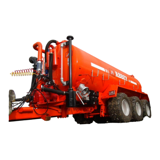
THE RANGE OF ABBEY TANKS INCLUDE Vacuum Tanks, Centivac Tanks, Open Top Tanks, & Injection Tanks. 1.0 THE FUNCTION OF THE TANKS The Abbey vacuum tank is a trailed machine which is capable of independently transporting liquid slurries from one area to another. The tanks are designed solely for agricultural use, but may in certain circumstances be used for transporting liquids for other purposes i.e. - Page 6 2.0 WORKING WITH SLURRY SAFTEY WARNING Unless adequate precautions are taken Liquid Manure Storage can pose a threat to the safety of both people and livestock. Slurry Tanks can contain gases which are produced by the decomposition of the slurry. These gases have been known to kill persons entering Slurry Storage Tanks as well as animals on slats above tanks which are being agitated.
- Page 7 Top Ball Valve Manometer Gauge Front Ball Valve Pressure Relief Valve Pump Control Handle Oil Drip Feed Adjustment Sight Glass Ram & Spring Assembly Inlet Valve 10. 2” High Pressure Hose Attachment 11. 6” Outlet...
- Page 8 6) Take care to match the tractor horsepower to tanker on soft sloping ground to prevent dangerous uncontrollable situations from occurring. 7) If you have any doubts as to the safety operation of the Slurry Tanker advice should be sought from your local dealer or direct from the Manufacturer.
-
Page 9: Machine Safety Labels
3.0 SAFETY WARNING (Con’d) 3.2 Machine Safety Labels The machine safety labels shown in this section are placed in important areas on your machine to draw attention to potential safety hazards. Tank: MAX. WORKING PRESSURE NOT TO Keep Wheel Nuts Tight EXCEED 0.5 BAR BEWARE OF TOXIC FUMES WHEN WORKING... - Page 10 3.0 SAFETY WARNING (Con’d) Additional if Ladder or Rain Gun fitted: DO NOT DANGER! CLIMB NEVER USE RAINGUN LADDER NEAR OVER HEAD WHILE POWER LINES MACHINE IS WORKING Never use the hydraulic rain gun attached When machine is moving orbeing to the tanker near overhead power lines operated do not climb the ladder Tandem Tankers:...
-
Page 11: Setting Up For Use 4.1 Vacuum Tanks
4.0 SETTING UP FOR USE VACUUM TANKS a) Connect Tanker to Tractor on pick-up Hitch or Draw bar. Measure P.T.O. Shaft leaving minimum 3” of closure to allow turning circle and shaft closing. Ensure P.T.O. Guards are fitted. If connecting to a tractor drawbar the necessary hitch eye reducer bush must be used. -
Page 12: Open Top Tanks
4.0 SETTING UP FOR USE (con’d) 4.2 OPEN TOP TANKS Connect the tanker to the tractor pick-up hitch. Measure the P.T.O. shaft as above and ensure all guards are in place. Connect up the hydraulic brakes and the tank lights, and check both are working. iii. - Page 13 4.0 SETTING UP FOR USE (con’d) Docking Station When the arm lowers the tanker side valve will open automatically Double Valves open automatically as the station is pushed down by the self-fill arm. Flexible suction hose feeding the station Priming the station Slowly pressurise the system fully and the valves will open.
- Page 14 4.0 SETTING UP FOR USE (con’d) Docking Station (Con’d) Aligning the Arm Align the arm rubber boot with the hopper near edge. Without the suction hose connected to the station, push the arm into the hopper and ensure the double valves operate and the docking station castors are free to manoeuvre to suit the arm.
- Page 15 4.0 SETTING UP FOR USE (con’d) Electronic & Electric Controls The following 8 functions can be operated on the tanker version. Gate valves x2, hydraulic top fill, Trailing shoe working and folding. Inlet turbo pump or rota cut filters. Self-Filler units and tandem axle steering. A feeder version is also available with other functions.
- Page 16 4.0 SETTING UP FOR USE (con’d) Components in the Electronic Control System Small cetop 3 solenoids control the minor functions while cetop 5 solenoids are preferred for motor functions Above are the electro hydraulic solenoids operated by the cab controller to work the hydraulic functions on the tanker.
- Page 17 4.0 SETTING UP FOR USE (con’d) Forced Steering Fitting the control rod mounting Tractor Pickup hitch, new control rod to be fabricated beside it. Mounting clevis. Horizontal distance of approx 240mm from pin to pickup hook Control rod Adjustable in length to suit the tractor Control rod mounting Preferably under the level of the pick up hook.
- Page 18 4.0 SETTING UP FOR USE (con’d) Re Setting Forced Steering First time setup. Remove locking bracket. Release all pressure from the system. Drive the tractor and feeder forward in a straight line for approx. 30m. To make sure axles are in line with the tractor. Adjust the length of the control rod until the control ram is stroked half its length.175mm for this ram Remove steering locking bracket...
-
Page 19: Operating Instructions 5.1 Vacuum System
5.0 OPERATING INSTRUCTIONS 5.1 Vacuum System VACUUM PUMP:It is recommended that the pump is run at maximum 250 R.P.M. for the first 3 hours of use. This is important to ensure that all parts of the pump are well lubricated. It is also recommended that you follow this procedure when the tanker has not been used for a long period of time. -
Page 20: Centivac System
5.0 OPERATING INSTRUCTIONS (CONT.) 5.2 CENTIVAC SYSTEMS To discharge tanker using rain gun. 1. Change handle on vacuum pump to central position, to release vacuum pressure. 2. Caution: Ensure P.T.O. shaft is disengaged. 3. Change handle on gearbox to centrifugal pump (i.e. rain gun). 4. - Page 21 5.0_OPERATING INSTRUCTIONS (CONT.) 5.2Turbo Pump Over Flow pipe Hydraulic Fill Valve Open 2” pressure limiter Turbo Pump left / Right front fill ONLY DANGER KEEP CLEAR Positions shown of rotating parts. Vacuum Pump On Vacuum & Turbo pump on/off prior to PTO ON Centivac Pump On Filling with Turbo Pump, Set as follows ( normal operation 1000 rpm) Hydraulic Fill valve tanker front OPEN (spread valve on side of tanker closes automatically)
- Page 22 5.0_OPERATING INSTRUCTIONS (CONT.) Rain Gun Pipe Work Rear spread valve Application rate setting Rain Gun isolation Valve Open Hydraulic spread valve Primary Stone trap Spreading with Turbo Pump ONLY, Set as follows (Normal operation 540 rpm) Hydraulic Spread valve Open on side of the tanker(Fill valve on front of tanker opens automatically). Vacuum pump in Neutral position and Vacuum Pump off.
- Page 23 5.0 OPERATING INSTRUCTIONS (CONT.) 5.3 OPEN TOP TANKS Operating instructions: 1. Fill the tank through the open top hopper. 2. Once full, the tank can then transport the slurry to the field. 3. Engage the P.T.O. and run at 540 r.p.m., while running the tank at the required ground speed. 4.
-
Page 24: Auto-Filler Unit
5.0 OPERATING INSTRUCTIONS (CONT.) 5.5 ABBEY AUTO-FILLER UNIT .Operating and Assembly Instructions: Description The Abbey Auto Filler arm is used to speed up the filling of the Abbey Vacuum tank without the operator leaving the tractor seat. The Abbey Auto Filler unit uses a rotating arm to lower the suction coupling into the filling hopper. Then the vacuum pressure of the tank will suck the coupling to the hopper creating a water tight seal so that the tank can be filled. - Page 25 Operating the Auto-Filler Unit Connect the two hoses to the tractor to operate the auto filler. Warning! Ensure all persons are standing clear before operating the arm. Check that the Auto filler is operating correctly and become very familiar with the hydraulic system before attempting to fill a vacuum tank.
- Page 26 5.0_OPERATING INSTRUCTIONS (CONT.) Operating the Bi-Directional Auto-filler Unit left to Right Movement To change the Bi-Directional Auto-filler Unit from Left to Right fill position the following procedure most be followed; Step 1 1. Raise Arm into Transport Position ensuring arm is locked in place for transport. 2.
- Page 27 5.0_OPERATING INSTRUCTIONS (CONT.) ABBEY Auto-Filler Unit Assembly/Parts Drawings Components Qty. Part No. Rubber Gasket for flanged valve ABY2080 Flanged Bend ABY35I Arm Reinforcing Plate ABY350 Double Flange Heavy Duty Gate Valve ART5F2-6 Double Flanged Adaptor 6” ABY352 Swivel Unit 6” ABYBP2001 /G Small Ram Mounting Plate ABY355...
- Page 28 5.0_OPERATING INSTRUCTIONS (CONT.) ABBEY Bi-Directional Auto-Filler Unit Assembly/Parts Drawings Pos. Component Qty. Part No. Pos. Component Qty. Part No. Hopper Stand ABY3564 Upper Ram Bracket ABY364 8”Auto Filler Hopper ABY357/8” Locking Bracket ABY365 8”Auto Filler Rubber Coupling ABYBP1101/H Locking Pin Spring ABY4946 Jubilee Clip CLP201-213...
-
Page 29: Steering Axle Tandem Tanks
5.0_OPERATING INSTRUCTIONS (CONT.) 5.6 STEERING AXLE TANDEM TANKS The following points should be understood when operating a Steering Axle Tandem Tanker. This axle is designed to operate and allow the tanker have a shorter turning circle compared to a rigid tandem. The rear steering axle follows the front tandem axle automatically and does not require the operator to mind the steering on the tank. - Page 30 5.0 OPERATING INSTRUCTIONS (CONT.) 5.7 Inverted Splash Plate X (mm) Approx. Spreading Width 11-12M (36') 4-5M (12') Note:- The cone must set up as shown to achieve the correct spread pattern. Pushing the splash plate down so that the half-moon shape band hits the rubber cone is not the prober set up. Spreading width may vary depending on the density of the slurry Check for blockages form time to time...
-
Page 31: Tanker Care And Maintenance
6.0 TANKER CARE AND MAINTENANCE 1. Daily check all wheel nuts are tight for the first working week and once a week thereafter. 2. Check that pressure relief valve on front of tank is free and working. also ensure the pressure gauge is fully functional at all times. - Page 32 6.0 TANKER CARE AND MAINTENANCE (CONT.) 21. Slack adjusters allow cam lever adjustment on the tandem tankers without the need to remove the lever (to take up wear on the axle shoes). Turning the bolt head on the slack adjuster will rotate the cam lever to increase the pressure applied to the shoes.
- Page 33 6.0 TANKER CARE AND MAINTENANCE (CONT.) Procedure on changing wheel: Call a tyre company to fix/replace the wheel. (These companies are professionals with proper lifting equipment and can have the wheel replaced or fixed on site, consider the cost is minimal compared to the costs associated with the serious consequences if something goes wrong) If this is not possible: Pull up to a level area and apply the handbrake (if fitted) on the trailed machine away from any major...
- Page 34 Please Note Positions on the following Tankers: Standard Range: Position on the flat under the side support between the axle and transport hook, only the Eco Range: side of the wheel change. Position on the flat under the side support between the axle bolts and transport hook, only the side of the wheel change Recess Range:...
- Page 35 Tandem Range: Position under the axle pivot pins, only the side of the wheel change. Note: It is up to the operator to evaluate that the machine is lifted securely at the suggested lifting points to prevent the lifting equipment slipping for any reason. Special Attention: Abbey has always supported its barrel on the ECO/Recess and Tandem Range with a full length chassis.
-
Page 37: Vacuum Pump 7.1 Use
7.0 THE VACUUM PUMP 7.1 USE 7.1.1 LUBRICATION Before starting, ensure that the Vacuum Pump is filled with oil either for the interior lubrication system or gearbox (overdrive). For internal lubrication, the min. oil level is stated by the mark at the lower end of the level (fig. 1) which is on manifold and consequently the max. - Page 38 7.0 THE VACUUM PUMP (Con’d) The overdrive has an oil level plug (Fig. 2 & 4) on the left side of the gearbox and indicates the level of oil to be maintained. For a right lubrication you have always to see the oil on the level. SE 10000,12000 &...
- Page 39 7.0 THE VACUUM PUMP (Con’d) 7.1.4 OIL REGULATION FOR LUBRICATION To regulate the oil fall, as from the above mentioned table, on the pump with force feed lubrication it is sufficient to operate on the regulation unit nut “A” (Fig. 5) after having loosened the nut “B”. Overpressure Valve Vacuum Control Valve Fig.5...
-
Page 40: Maintenance
7.0 THE VACUUM PUMP (Con’d). 7.2 MAINTENANCE 7.2.1 VALVES Check periodically that float and safety valves placed on the tank are in perfect working order. 7.2.2VANES Check the wear of the vanes placed on the vacuum pump and replace the complete set when the height is sensibly reduced (about 10-15% of the original height). - Page 41 Use a brush and Once a year or for prolonged Wash lubrication pump compressed air inactivity Check that the overflow valves are working correctly Remove valves Monthly Oil the P.T.O. with a brush Lubricate the power take-off and lubricating oil Monthly Wash and clean the valves Remove valves...
-
Page 42: Replacement Parts
8.0 Replacement Parts 8.1 Vaccum Tank Pressure System Item Part Item Description Description Part Number Number Top Trap Vacuum Pump 60mm Top Trap ABY9017 1 1/2" Safety Valve ART13-1 1/2 80mm Top Trap ABY9021 Rubber Ball ABY2135-100 100mm Top Trap ABY9050 Rubber Washer ABY2140-L... - Page 43 8.0 Replacement Parts (Con’d) 8.2Back Door Assembly (24”) Item Description Part Number 6" Heavy Duty Gate Valve ART5F2/51 6" O-Ring ART6F-6-10 Rear Door Seal ABY2170-44X25MM Door Closing Hook ABY2179 Ring Nut Ring Nut M20 M12x30 DIN 931-1 - M12 x 30 M12 Lock Nut DIN985- M12 Pin For Back Door...
- Page 44 8.0 Replacement Parts (Con’d) 8.3 Chassis Parts Item Part Number Description Spring Plate ABY4356200TP Cross Plate ABY4356200BP M16x40 DIN913-1-16x40 M16 Lock Nut DIN085-M16 Grease Nipple NIP1/8X180 Parabolic Spring ABY4356200 M20x120 DIN982-M20X120 12.9 M20 Lock Nut DIN085-M20 Pivot Pin ABY3523B Grease Pipe ABY3528 Handbrake Lever ABY3618...
- Page 45 8.0 Replacement Parts (Con’d) 8.4 Additional Parts Item No: Description Part Number 3" Treaded Sleeve ABY2156-3 O-Ring ABY2154-3 Glass Eye ABY2152-3 O-Ring ART6F-6-10 6" Gate Valve ART7F2-6 Manual Handles ABY9135 Clevis ART5-6-9 Rubber Flange ABY2080 Blank Off Plate ABY2080/1 Flanged sleeve ABY2085...
- Page 46 8.0 Replacement Parts (Con’d) 8.5 Centivac System Item Item Description Part Number Description Part Number Centivac Bolt On Clip 113-121mm CLP113-121 Hitch DIN931-1-M16x60 12.9 M16x60 bolt 6" Gate Valve ART7F2-6 Grade M16 Flat Washer DIN125A-M16 M12x35 DIN 933-M12x35 DIN985-M16 12.9 M16 Lock Nut 4"...
- Page 47 8.0 Replacement Parts (Con’d) 8.6 Manual & Hydraulic Change Over Manual Activating Handle to suit All MEC Pumps Sold in Kit form only Part No: ABY9180 __________________________________________________________________________ Part No: ABY9160 (10,000/12,000) Part No: ABY9140 (MEC Pumps) __________________________________________________________________________________________ Part No: ABY9160-CL (MEC Pumps)
- Page 48 8.0 Replacement Parts (Con’d) 8.7 Vacuum Pumps...
- Page 49 8.0 Replacement Parts (Con’d)
- Page 50 8.0 Replacement Parts (Con’d)
- Page 51 8.0 Replacement Parts (Con’d)
- Page 52 8.0 Replacement Parts (Con’d)
- Page 53 8.0 Replacement Parts (Con’d)
- Page 54 8.0 Replacement Parts (Con’d) 8.9 Garda Pump with Gland Seal...
- Page 55 8.0 Replacement Parts (Con’d)
- Page 56 8.0 Replacement Parts (Con’d) 8.19 Garda Pump With Menacial Seal Part Number Description Part Number Description GRDG60 / GRDG10 Circlip Ø 25 E TS Gearbox WPT-STAR 1000RPMTURBO SYSTEM WPT1000 GRDG11 Screw M 10x25 TE GRDG61 / 1000 Central gearwheel GARDA 1000 RPM Z 86 - M 3 GRDG14 Screw M 12x35 TE GRDG62 / 1000...
- Page 57 8.0 Replacement Parts (Con’d) Turbo Pump Part Number Description GRDG20 Smooth washer Ø 10 GRDG30 Blank washer Ø 30x56 GRDG35 Ball bearing GRDG36 Key 8x7x50 GRDG37 Self-locking nut M 30x2 GRDG39 Screw M 12x30 TE GRDG40 Smooth washer Ø 12 GRDG42 Seal ring Ø...
- Page 58 8.0 Replacement Parts (Con’d)
- Page 59 8.0 Replacement Parts (Con’d)
- Page 60 8.0 Replacement Parts (Con’d) 8.10 Traps...
- Page 61 8.0 Replacement Parts (Con’d) 8.11 Axles 350X60 Braked Axel Item No: Description Part No: Brake Assembly ADR9RE0014 Camshaft ADR9RE0014 Retaining Ring ADR9RE0014 Washer ADR9RE0014 M24x1,5 ADR9RE0014 Spring ADR9RK0004 Lever ADR9RQ0001 Drum 8 Holes ADR66LNF0804...
- Page 62 8.0 Replacement Parts (Con’d) 400X80 Braked Axel Item No: Description Part No: Brake Assembly ADR9RE0048 Adapter ADR9RE0048 Camshaft ADR9RE0048 Retaining Ring ADR9RE0048 Washer ADR9RE0048 M24x1,5 ADR9RE0048 Spring ADR9RK0005 Lever ADR9RQ0001 Drum 8 Holes ADR66LNF0801...
- Page 63 8.0 Replacement Parts (Con’d) ADR 1800x150 Axel420x180 Brake Shoe...
- Page 64 8.0 Replacement Parts (Con’d) ADR 1800x150 Axel420x180 Brake Shoe...
- Page 65 8.0 Replacement Parts (Con’d) ADR 1800x150 Axel420x180 Brake Shoe...
- Page 66 8.0 Replacement Parts (Con’d) Tandem Bogie...
- Page 67 8.0 Replacement Parts (Con’d)
-
Page 68: Trouble Shooting
9.0 Trouble Shooting For Slurry Tankers Don’t panic, take your time and think through the problem logically, LOOK FOR THE OBVIOUS! Things like damaged hoses, loose fittings or wrongly connected quick release fittings (at the tractor) will cause problems. Try to identify common conditions or circumstances where the problem exists. Change only one thing at a time when trying to identify the problem area, if that doesn’t solve it, put it back the way it was, and then try the next thing. - Page 69 9.0 Trouble Shoot For Slurry Tankers (Con’d) Garda Pump 8. Leaking from glad pack from gearbox to pump: This is normal. This should be leaking slightly to keep gland lubricated Excessive leaking will require gland to be replaced 9.
- Page 70 10.0 Warranty The following warranty terms relate to parts only. Abbey Machinery LTD will not accept claims for labour or mileage. 1. This Vacuum Tanker is covered by the manufactures warranty for twelve months or one season. 2. Vacuum Tankerused by agricultural contractors is covered by manufactures warranty for six months from the date of purchase.
-
Page 71: Terms And Conditions
11.0 Terms and Conditions of Sale General Consideration: Abbey Machinery Ltd, shall hereinafter be referred to as “the Company”. All products and/or components or whatever kind and all services sold by the company shall be sold subject to these Terms & Conditions of Sale and shall hereinafter be referred to as “the Goods”. - Page 72 Repairs and Alterations Any products accepted for repair or alterations by the Company shall be held by the Company and repaired and altered by it entirely at Customer’s own risk. Force Majeure If circumstances occur which could not have been foreseen at the time the contract was concluded and which are beyond the control of the company and directly or indirectly prevent, hinder or make more difficult the full or partial performance of the contract, such circumstances being, inter alia war, threat of war, civil war, natural disasters, riots, strikes, lockouts, fire, breakdowns in the Company’s factory,...
Need help?
Do you have a question about the Slurry Tanker and is the answer not in the manual?
Questions and answers