Table of Contents
Advertisement
Quick Links
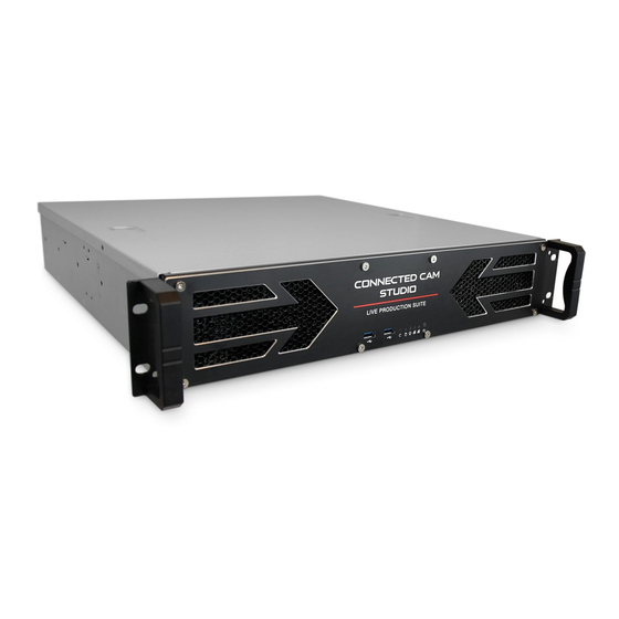
KM-IP6000
(6 input version)
KM-IP4100
(4 input version)
LIVE PRODUCTION SUITE
SOFTWARE USER'S MANUAL
June 2019
JVCKENWOOD Corporation
JVC Professional Video
http://pro.jvc.com/studio
All information in this document is subject to change without notice.
© JVCKENWOOD Corporation, 2019. All rights reserved.
Page 1
Advertisement
Table of Contents

Related Manuals for JVC KM-IP6000


Summary of Contents for JVC KM-IP6000
- Page 1 (6 input version) KM-IP4100 (4 input version) LIVE PRODUCTION SUITE SOFTWARE USER’S MANUAL June 2019 JVCKENWOOD Corporation JVC Professional Video http://pro.jvc.com/studio All information in this document is subject to change without notice. © JVCKENWOOD Corporation, 2019. All rights reserved. Page 1...
- Page 2 MULTI-CAMERA LIVE PRODUCTION AND STREAMING KM-IP6000 KM-IP4100 SMARTER - FASTER - EASIER...
-
Page 3: Table Of Contents
SA - JVC Camera Control Tab ........ - Page 4 Streamstar and are protected by international copyright laws. The JVC logo is property of, and used with permission of JVCKENWOOD corporation. The contents of this document may be used exclusively for information purposes as a learning resource for users of the described systems. Any other use including reproduction, modification, distribution, transmission, re-publication, display or performance of the contents of this document without prior written consent of Streamstar is expressly forbidden.
-
Page 5: Introduction
WELCOME Congratulations on your purchase of the CONNECTED CAM STUDIO, the ideal live production system for the new generation of digital native media professionals. CONNECTED CAM STUDIO - Live Production Software The CONNECTED CAM STUDIO SW is specifically designed for live streaming production. It features a highly effective, intuitive touch screen user interface, that has been fine tuned and tested in thousands of real life productions. -
Page 6: Gui Overview
MONITORS/SWITCHES Section CONTENT MANAGEMENT & SETTINGS section Info bar KM-IP6000 NOTE: The GUI of the 4 cam version is modified to make the best use of the available desktop space. The LAYERS switches are located on the left of the PGM. - Page 7 CREATING A PROJECT After application start the 1st GUI screen appears. Two large buttons appear in the center of the CONTENT MANAGEMENT AREA. 1 - NEW PROJECT - a new project is created and you can start working immediately 2 - LOAD PROJECT - a dialog screen appears with a list of previously saved projects. KM-IP4100 NOTE: To get you started after the SW installation a QUICK TUTORIAL is provided to get basic operational instructions.
-
Page 8: Production Layout Section
PRODUCTION LAYOUT Section KM-IP6000 It is located at the very top of the GUI and contains all important functionality controls for the creation of the layout and the overall appearance of your production (PGM output) as well as controls of certain related software functions. - Page 9 Image 1 - Selecting the PIP template KM-IP6000 Image 2 - Assigning sources to the PIP template areas KM-IP6000 Operating procedure - continued... 4. When all PIP screen areas are populated/filled with content a red GO LIVE button at bottom activates 5.
-
Page 10: Screen Layout - Split Screen
The operating procedure of the SPLIT SCREEN is identical to the of the PIP. Please refer to the previous page for instructions. The only difference is that now you are working with SPLIT SCREEN TEMPLATES. Selecting a SPLIT template KM-IP6000 Selecting sources for the SPLIT areas KM-IP6000 MIXING MODES: Tap/Click any of the three switches to select a switching mode with their respective functionality controls. -
Page 11: Crossfade
Crossfade Duration Adjustment: The image bellow shows the CROSSFADE ADJUSTMENT controls window open. - Use the DURATION BAR to adjust the duration of the crossfade. Slide the red bar to the right to increase the crossfade duration, ...to the left to decrease it. Or tap/click anywhere on the duration adjustment bar to set a new duration. -
Page 12: Ptz Camera Control
JVC PTZ CAMERA PRESETS and PTZ CAMERA GROUP PRESETS controls display If JVC PTZ cameras are connected to the system, activating the PTZ CAMERA PRESETS and PTZ CAMERA GROUP PRESETS buttons will display their respective control switches superimposed over the camera preview and PGM preview monitors. -
Page 13: Live Camera Monitors
Tap/click on the AUTOCUT to specify which camera will go to live PGM once the Media/Replay is finished. d, PTZ CAMERA PRESETS control switches If JVC PTZ cameras are connected to the system the PTZ CAMERA PRESETS control switches may be displayed superimposed over the corresponding camera monitors to allow instant access to PTZ camera presets. - Page 14 CONNECTED CAM STUDIO KM-IP6000 6 CHANNEL LIVE PRODUCTION AND STREAMING STUDIO Page 14...
-
Page 15: Content Management And Settings Section Overview
MEDIA LIBRARY, REPLAYS, PLAYLISTS, OVERLAYS and CG controls. The SA (Settings Area) has 4 TABS on the top that reveal the control elements for: SYSTEM SETTINGS, AUDIO MIXER, REPLAYS, JVC CAMERA CONTROL. The image below shows the PLAYLISTS controls in CMA and SYSTEM SETTINGS in the SA. -
Page 16: Media Tab
CMA (Content Management Area) - MEDIA Tab Opens the MEDIA LIST pane with all interface elements to operate the MEDIA playback functionality. The MEDIA pane top bar contains 2 TABS: A - SELECT MEDIA DIRECTORY - Windows OS access to select the directory which contains your video files B - OPEN MEDIA DIRECTORY - Windows OS access to manage the selected directory content Media List Item Media List Item... -
Page 17: Media In/Out Point Editor
MEDIA IN/OUT POINTS EDITOR Enables you to trim your media file by setting up IN/OUT points for media playback. The functionality is non-destructive and your physical media files are untouched. You can reset the IN/OUT points at any time. Enter the IN/OUT points editor by tap/click on any MEDIA IN/OUT POINTS EDITOR BUTTON in the media file list display - indicated by the yellow arrows in the image bellow. - Page 18 2nd row - IN/OUT POINTS SET/NAVIGATE (left to right) F - GO TO IN Point - moves the playhead to the IN point location G - IN POINT Time - displays the IN point time H - MARK IN Point button - tap/click to set the IN point I - MARK OUT Point button - tap/click to set the OUT point J - OUT POINT Time - displays the OUT point time K - GO TO OUT Point - moves the playhead to the OUT point location...
-
Page 19: Autocut
A COUNTDOWN TIMER inside the AUTOCUT button indicates the remaining time of the M/PL. If a M/PL is set to loop, the countdown timer is showing the remaining time of the M/PL currently playing. AUTOCUT switches AUTOCUT switches KM-IP6000 Page 19... -
Page 20: Replays Tab
CMA (Content Management Area) - REPLAYS Tab CONNECTED CAM STUDIO features an extremely powerful and unique replay system specially designed to make the replays operation fast and easy. The CMA Replays Menu reveals the REPLAYS LIST of all captured REPLAY SETS. Each REPLAY SET in the Replays List contains all interface elements to operate the REPLAY functionality. -
Page 21: Replay Capture
(the length can be set in REPLAY SETTINGS - default is 6 sec.) 3. LONG triggers the capture of 10, 15 or 20 sec. replays in all cameras (the length can be set in REPLAY SETTINGS - default is 10 sec.) SA - Replay Capture buttons and Time/Score Controller KM-IP6000 Page 21... - Page 22 Replay Capture and Playback procedure 1. Activate the REPLAY TAB on top of the SA to reveal the REPLAY CAPTURE buttons in SA and open the REPLAYS LIST in the CMA. In a new project there are no replays captured yet, hence and empty list. 2.
-
Page 23: Replay Modes
REPLAY MODES CONNECTED CAM STUDIO features a very unique and extremely efficient, easy-to-use replay system that doesn’t require special training or an extra operator. It offers 3 different MODES to work with replays, that provide many creative possibilities. 1. NORMAL MODE 2. -
Page 24: Replay Favorites And Highlights
DRCS - DYNAMIC REPLAY CAMERA SWITCHING mode Allows switching camera angles during replay playback. 1. Tap/click the DRCS MODE ICON to activate the DRCS MODE. (outlined in yellow) The numbered REPLAY CAMERA buttons group in a block to indicate the DRCS MODE. 2. -
Page 25: Autocut In Replays
DELETING REPLAYS Replay Sets are stored internally as time-stamped files for each camera separately. Deleting a Replay Set is a destructive operation, which physically erases the files from storage. AUTOCUT IN REPLAYS Allows users to select a live camera, that will be switched to PGM automatically, after a Replay ends. When a replay is switched to Live PGM the AUTOCUT SWITCH appears on top of the lower portion of all Camera Monitors. - Page 26 CONNECTED CAM STUDIO KM-IP4100 4 CHANNEL LIVE PRODUCTION AND STREAMING STUDIO Page 26...
-
Page 27: Playlists Tab
CMA (Content Management Area) - PLAYLISTS Tab Opens the PLAYLISTS pane with control elements to operate the PLAYLISTS functionality. Playlists are virtual collections of MEDIA files or REPLAYS assembled in a list for continuous playback. Each Playlist can be expanded with the EXPAND button to reveal its content. Each Playlist Item contains a set of control elements to control its behavior in the Playlist. -
Page 28: Overlays Tab
PNG files with transparency/alpha channel and FLV animations with transparency are supported. The OVERLAYS controls are accessed via the OVERLAYS TAB within the left side menu in the CMA. OVERLAYS LAYER SWITCH ON/OFF KM-IP6000 LOAD 1st 10 FILES INTO SLOTS 10 OVERLAY GRAPHICS SLOTS AVAILABLE... -
Page 29: Cg Tab
CMA (Content Management Area) - CG Menu Tab It contains a list of CG OBJECTS with all control elements to operate the CG functionality. The CHARACTER GENERATOR - CG enables you to insert real time generated graphics to your live PGM. There are 3 types of CG objects that can be created within the CONNECTED CAM STUDIO CG system: 1. -
Page 30: Cg Operation Procedure
C. Tap/click the CG thumbnail in the list to select it - outlined in red when selected D. Switch the CG Layer to live PGM using the CG switch in the LAYERS section. KM-IP6000 NOTE: The CG Object TYPE is indicated by the CG Type ICON under the CG Name. -
Page 31: Cg Object Construction And Editing
CG OBJECT CONSTRUCTION All CG objects are constructed from separately controlled layers. Depending on the type the CG Object will have different layers that need to be setup. All CG Objects contain a GRAPHIC BACKGROUND layer plus several other - either editable or dynamic text layers that are positioned on top of the background layer. -
Page 32: Text Layer Parameters Setup
TEXT Layer parameters setup • Edit/Type the text content in the text field • Format the text using the provided controls - Font, Size, Line Spacing, Style, Opacity, Alignment in a usual text editor way. • Setup the text position using the X-POS, Y-POS, Text Block Width, Text Block Height properties •... - Page 33 CRAWL DIRECTION and LOOP parameters setup • Use the LOOP button to loop the crawl text. • Use the CRAWL DIRECTION buttons to specify the crawl direction. NOTE: The loop is only active for as long as set by the OUT TIME parameter which has priority. The OUT TIME setting will terminate the crawl loop playback .
-
Page 34: Timer/Score Cg Objects
TIMER/SCORE CG Objects This type of CG Object allows you to create live sports graphics dynamically controlled via the TIME/SCORE CONTROLLER. It is revealed via the [0:0] tab in the SA MENU and/or the TIMING OPTIONS Tab found in the CG Tab of the CMA Left Side Menu. The controller is displayed within the SA (Settings Area) to allow simultaneous operation of the live game graphics controls along with operating other functionalities of the SW. -
Page 35: Timing Options Tab
CG PANE - TIMING OPTIONS TAB This is where the dynamic layers data output logic is setup. The output of the TIMER/SCORE CG Object may vary significantly depending on how the various parameters in this pane are set. Please read this sec- tion carefully and familiarize yourself with all the settings and their effects on the display of the system to avoid unexpected or confusing results. -
Page 36: Game Part Parameters Setup
GAME PARTS Parameters Setup 1. GAME PART use the +/- buttons to set the Number of Game Parts in the game. NOTE: This value needs to be set if you wish to count time by Game Parts. 2. GAME PART TIME - use the +/- buttons to set the Duration of an individual Game Part alternatively you can type in the numeric value directly NOTE:... -
Page 37: Timer/Score Live Game Controller
TIMER/SCORE LIVE GAME CONTROLLER Push the big SHOW/HIDE button to reveal / hide the Live TIME /SCORE CONTROLLER in the SA to allow for live game control / manual control of the data in the dynamic layers of Timer/Score CG Objects. TIMER/SCORE CONTROLLER functionality 1. -
Page 38: Automatic Data Control
AUTOMATIC DATA CONTROL The internal Timer Score CG systems dynamic data can be controlled from external sources via XML data. Procedure: 1. Select the source of XML data by the drop-down selector box. It can be either an XML file or a separate custom made application that is capable of sending pre-formated XML data for the CG system over IP. -
Page 39: Editing And Xml Preset
EDITING AN XML PRESET Clicking the EDIT button in step [7] on the previous page you will enter the XML PRESET SETUP. 1. Click the file selector to select the XML file to be used for external data control 2. The XML file content will show in the scroll window on the left. 3. -
Page 40: Settings Area Menu
KM-IP6000 3. REPLAYS Tab SA - Replay capture buttons with Live Time/Score Controller CMA - Replays List KM-IP6000 4. JVC Tab SA - camera selection buttons CMA - JVC camera controls KM-IP6000 Page 40... -
Page 41: Sa - System Settings Tab
6 cam system 2nd Monitor Output Grid example All cameras preview grid PGM + All cameras + Ingest previews grid KM-IP6000 KM-IP6000 SYSTEM SETTINGS / GENERAL / Camera Input tab Use the side menu to select an input and choose an input type from the drop-down menu for each. -
Page 42: Synchronization Tab
SYSTEM SETTINGS / GENERAL / SYNCHRONIZATION Setting tab Use it to synchronize remote IP cameras. 1. Select cameras to be synchronized by pushing the numbered buttons KM-IP6000 2. Select the camera which will be the MASTER 3. Push SYNCHRONIZE to start the sync on all se-... -
Page 43: Streaming - Streaming Destinations / Add New Destination / Encoding Tabs
SYSTEM SETTINGS / STREAMING / Streaming Destination tab Login Data Input for the selected streaming platform - fill in data and SAVE. The tab content will display the setup destinations in a list view. SYSTEM SETTINGS / STREAMING / Streaming Destinations tab - list view Multiple Streaming Destinations List - streaming controls START, EDIT and DELETE buttons for each streaming destination are provided. -
Page 44: Recording - Recording / Iso Recording Tabs
SYSTEM SETTINGS / RECORDING / Recording Settings tab PGM high quality recording setup - start/stop, recording / remaining time, and disks info are provided SYSTEM SETTINGS / RECORDING / ISO Recording Settings tab All camera ISO recording setup, define drives, paths, start/stop recording, storage space info SYSTEM SETTINGS / LAYERS / Ingest tab A transparency color key can be created on the INGEST input. -
Page 45: Replays Settings - Replay Cameras / Replay Settings / Lead In/Out Wipes Tabs
SYSTEM SETTINGS / REPLAYS / Replay Cameras tab Click buttons to select/deselect cameras for replay use. 4-cam version only shows 4 channels. KM-IP6000 SYSTEM SETTINGS / REPLAYS / Replay Settings tab Setup the behavior of replays, replay durations and slow motion playback settings. -
Page 46: Appearance - Pip / Split / Background Tabs
1. Select a device for IFB audio talk back using the drop-down menu 2. SHOW/HIDE buttons reveal an additional ON/OFF button in the SA MENU 3. Use this info to set RETURN OVER IP SERVER setting in the JVC camera 4. TALK/MUTE button switches the audio device used for communication ON/OFF 5. -
Page 47: About
SYSTEM SETTINGS / ABOUT / About tab Provides system information and license key entry button SYSTEM SETTINGS / ABOUT / Legal Notices tab Display of mandatory legal info. SYSTEM SETTINGS / EXIT Tap/click the EXIT button to close the application Application shut down / system shut down dialog Page 47... -
Page 48: Sa - Audio Tab
SA (Settings Area Menu) - AUDIO Activates the display of the AUDIO MIXER in the CMA and the REPLAY CAPTURE buttons in the SA. The AUDIO MIXER board provides all the standard Audio for Video mixer interface elements. 1. Cameras SDI embedded audio faders with level and peak indicators 2. -
Page 49: Sa - Replays Tab
SA (Settings Area Menu) - REPLAYS Activates the display of the REPLAY CAPTURE BUTTONS in the SA(Settings Area) and the REPLAYS LIST in the CMA (Content Management Area) Activating another functionality in the left side menu will change the content of the CMA but as long as the SA REPLAY SWITCH IS ON the replay capture buttons will remain available. -
Page 50: Sa - Jvc Camera Control Tab
SA (Settings Area) - JVC CAMERA CONTROL Menu Tab It provides all the interface elements to remotely control JVC camcorders or PTZ cameras - over IP. It is divided into 4 TABS with various logically related controls. 1. IP CONNECT - contains all parameters to establish a connection to a camera 2. -
Page 51: Zoom And Focus
For details on the functionality and settings of JVC cameras please refer to your camera users manual. PTZ PRESETS Tab If a JVC PTZ camera is connected to the CONNECTED CAM STUDIO this tab will be available providing access to its PRESET controls: • Pan/Tilt with movement speed adjustment slider •... -
Page 52: Ptz Groups Presets
PTZ GROUPS PRESETS Tab Provide access to the JVC - PTZ camera groups controls: • Combine individual camera presets into 14 groups of GROUP PRESETS • Execute a Group Presets - instantly move multiple cameras to positions assigned in the group preset... -
Page 53: Ptz Presets Gui
3. Tap/click on the Preset button (2A) reveals a PRESETS GRID of all available presets for this PTZ camera a - These presets are created in the PTZ CAMERA PRESETS pane in the JVC PTZ Tab. b - tap/click any of the PRESET (P1-P14) buttons and the camera moves to that position immediately c - tap/click the [ X ] button in lower right to close/hide the PRESETS GRID. -
Page 54: Ptz Groups Presets Gui
3. Tap/click the Preset button (2c) reveals the GROUP PRESETS GRID and it’s controls a - Numbered presets created in the PTZ CAMERA GROUP PRESETS pane (G1 - G14) in the JVC PTZ CAMERA GROUPS PRESETS Tab. b - tap/click to select any of the PRESET (G1 - G14) -
Page 55: Support
For more information on CONNECTED CAM STUDIO please visit: http://pro.jvc.com/studio For support visit: http://pro.jvc.com/studio/support Thank You for using CONNECTED CAM STUDIO. Enjoy! Page 55...