Table of Contents
Advertisement
Quick Links
Advertisement
Chapters
Table of Contents

Related Manuals for Roland Groovebox MC-707


Summary of Contents for Roland Groovebox MC-707
- Page 1 Reference Manual © 2019 Roland Corporation...
-
Page 2: Table Of Contents
Contents Panel Descriptions Pad Operations . . . . . . . . . . . . . . . . . . . . . . . . . . . . . - Page 3 Contents Recording Knob Movement in Steps Assigning Parameters to the Knobs . . 34 (MOTION) . . . . . . . . . . . . . . . . . . . . . . . . . . . . . . . . . . . 51 (KNOB ASSIGN) .
- Page 4 Contents Parameter List MFX/IFX Parameters . . . . . . . . . . . . . . . . . . . . . . . . . . . . . . . . 61 .
-
Page 5: Panel Descriptions
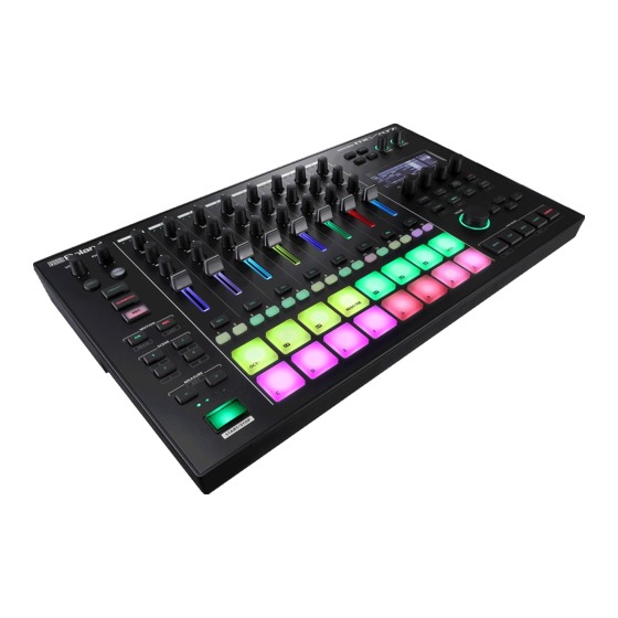
Panel Descriptions Top Panel Playback position indicators Measure indicators SCENE [1]–[4] button Common Section 1 The combination of clips being played back by the tracks of the [VOLUME] knob MC-707 is called a “scene . ” Adjusts the volume of the MIX OUT jacks. You can recall a stored scene by pressing a SCENE [1]–[4] button. - Page 6 Panel Descriptions [SOUND] button Pad Section Accesses the sound browser screen. Step [1]–[16] buttons By holding down the [SHIFT] button and pressing the [SOUND] Use these buttons to select the step that you want to edit. button, you can access the sound settings screen. &...
-
Page 7: Rear Panel
These jacks let you connect an external effect unit and use it as a downloaded file. track effect or total effect. & https://www .roland .com/support/ ASSIGNABLE OUT jack MIDI port You can output a specific track from the ASSIGNABLE OUT jacks. -
Page 8: Introduction
Introduction Turning the MC-707 On * Before turning the unit on/off, always be sure to turn the volume down. Even with the volume turned down, you might hear some sound when switching the unit on/off. However, this is normal and does not indicate a malfunction. Power-on your equipment in the order of MC-707 0 connected equipment . -
Page 9: An Overview Of The
An Overview of the MC-707 The MC-707 can simultaneously play back up to eight independent tracks. You can assign up to 16 clips to each track, and switch between these clips during playback. External equipment SEND jacks RETURN jacks MC-707 Project Project User... -
Page 10: What Is A Project
An Overview of the MC-707 What Is a Project? What Is the Browser? “project . ” On the MC-707, data for one song is handled as a unit called a This lets you select the material that you need for the project that Projects are saved on an SD card. -
Page 11: Basic Operation
Basic Operation Loading and Playing a Project Changing the Clips that Play On the MC-707, data for one song is managed as a unit called a The HOME screen appears . “project . ” Projects are saved on an SD card. A project contains tracks, clips, tone data, and data for the samples that are used. -
Page 12: Importing A Clip
Basic Operation Importing a Clip Move the cursor to the position at which you want to import a clip . Press the [CLIP] button . The clip browser shows the projects that are in the SD card. When you use the cursor buttons to select a project, the clips inside it are shown . - Page 13 Reference Section...
-
Page 14: Main Screen
Main Screen HOME Screen Clip number, clip name Shows the number of the current track, the clip number, and clip When the MC-707 starts, the home screen appears. name. Level meter Shows the output volume of each track. If a stop-reservation (stop at the next switch) occurs in a track, this is shown with a mesh overlay. -
Page 15: Copying The Sound Or Phrase Of A Clip (Copy/Paste)
Main Screen When the copy is completed, a message appears in the upper part Copying the Sound or Phrase of a Clip of the screen. (COPY/PASTE) Here’s how to duplicate the data of a clip or a sound. You can make a complete duplicate of a clip, or you can duplicate individual lines of a clip. -
Page 16: Reloading A Clip (Reload)
Main Screen Reloading a Clip (RELOAD) Here’s how to recover the specified clip by loading it from the SD card. Use the cursor buttons to select the clip that you want to reload . Use the [C4] knob to select “RELOAD,”... -
Page 17: Project Operations
Project Operations What Is a Project? Managing Projects On the MC-707, data for one song is handled as a unit called a “project . ” Here’s how to protect or delete project files on the SD card. Projects are saved on the SD card. Press the [PROJECT] button . -
Page 18: Making Project Settings
Project Operations VOICE RESERVE tab Making Project Settings Parameter Value Explanation Here’s how to make settings such as the project’s volume and the pad illumination colors. Specifies how polyphony resources are allocated to each tone/drum track. Press the [PROJECT] button . The track is given priority for the TRACK 1–8 0–10... -
Page 19: Managing Samples Loaded Into A Project
Project Operations Managing Samples Loaded into a Project Saving a Project (Sample Bank) Here’s how to save the project to the SD card. Here’s how to manage the samples that are loaded into a project. Press the [PROJECT] button . Press the [PROJECT] button . -
Page 20: Track Operations
Track Operations M EMO Creating a Track You can also execute by pressing the [C4] knob once again. The MC-707 has four track types: TONE, DRUM, DRUM + COMP, and With the track that you want to delete selected, press the LOOPER. - Page 21 Track Operations Parameter Value Explanation Specifies the width of the mid frequency range. EQ Mid Q 0.5–16.0 Set a higher value for Q to narrow the range to be affected. EQ High Gain -24–+24 [dB] Gain of the high frequency range. EQ High Frequency 20–16000 [Hz] Frequency of the high range.
-
Page 22: Pad Operations (Pad Mode)
Pad Operations (PAD MODE) Changing a pad’s color Using Mute Mode & “Making Project Settings” (p. 18) This lets you use the pads to mute tracks or stop/play clips. Using Clip Mode Press the [MUTE] button . Operation switches to Mute mode. When you press the PAD MODE button CLIP, the pads switch to Clip mode. -
Page 23: Playing
Pad Operations (PAD MODE) TR-REC tab Playing Parameter Value Explanation TONE track Specifies the velocity when using TR-REC to For a TONE track, you can play the pads as a keyboard. input a drum track. VELOCITY 1–127 1–127 COLOR tab REST OCT- OCT+... -
Page 24: Scatter Mode
Pad Operations (PAD MODE) Specifying a chord Using the [SCATTER] Button to Apply the Effect Use the [C1]–[C4] knobs to edit the value . Turning a knob: 1 (C-1)–127 (G9) While in Scatter mode, press the [SCATTER] button . Pressing a knob: Switches on/off Step mode is selected. -
Page 25: Importing Clips (Clip Browser)
Importing Clips (Clip Browser) The clip browser lets you import clips from a project saved on the SD card. In the home screen, use the cursor buttons to select the clip slot into which you want to import a clip . Press the [CLIP] button . -
Page 26: Selecting Sounds (Sound Browser)
Here’s how you can load samples that are saved on the SD card. ALPHA: Sort in alphabetical order. * Samples that you want to load must be placed in the ROLAND/GROOVEBOX/ BANK A–F: Filter by bank. SAMPLE folder of the SD card. - Page 27 Selecting Sounds (Sound Browser) The content that can be loaded depends on the track type TONE LOOPER DRUM DRUM track track track track (kit) (INST) Loading a preset sound (PRESET) Loading a sound from a project on the SD card (PROJECT) Loading a sample from a project on the SD card...
-
Page 28: Step-Recording A Phrase
Step-Recording a Phrase When the pads are in Note mode, you can use the step buttons and the Changing the Measure Settings pads to step-record phrases. You’ll create a pattern by specifying the steps at which each pad will Hold down the [SHIFT] button and press the MEASURE [<] [>]... -
Page 29: Editing The Notes Of Each Step
Step-Recording a Phrase Editing the Notes of Each Step Hold down the [SHIFT] button and press the step button . The STEP EDIT screen appears. The notes of the selected step are shown. Use the cursor to select the note that you want to edit . NOTE tab Knob Explanation... -
Page 30: Drum Track: Tr-Rec
Step-Recording a Phrase Drum Track: TR-REC Parameter Explanation/Controller Adjusts the velocity. [C1] knob Press the PAD MODE [NOTE] button . Adjusts the timing at which the start note begins. START The pad mode is set to Note mode. [C2] knob NOTE (1/2) tab Press a pad (key) to select the pad that you want to edit . -
Page 31: Specifying The Last Step And First Step
Step-Recording a Phrase Specifying the Last Step and First Step Specifying the Last Step By specifying the Last Step, you can make a mid-way step play as the last step. Press the PAD MODE [NOTE] button . The pads are in Note mode. Hold down the [SHIFT] button and press the... -
Page 32: Recording
Recording You can record your performance or audio, and save it as clips. Recording Audio on a Looper Track Recording a Performance to a Tone or Creating a new clip and recording Drum Track Hold down the [SHIFT] button and press the [INPUT] button . -
Page 33: Quantize
Quantize Two types of quantization can be applied to tone tracks and drum tracks. ME M O Quantization cannot be applied to a looper track. INPUT QUANTIZE The timing of the performance is corrected (quantized) during recording. If this setting is on, irregularities in the performance timing are not recorded. -
Page 34: Recording Knob Movement In Steps (Motion)
Recording Knob Movement in Steps (MOTION) Movements of the [FILTER], [MOD], and [FX] knobs (MOTION) can be Editing Motion recorded in a clip. In the EDIT STEP screen, you can edit the Motion for each step. Turning Motion On/Off While holding down the [SHIFT] button, press a step button . - Page 35 Recording Knob Movement in Steps (MOTION) Deleting Motion from a step While holding down the [SHIFT] button, press a step button . The EDIT STEP screen appears. Press the cursor [<] button to select the “MOTION” tab . Use the MEASURE [<] [>] buttons and the step buttons to select the step from which you want to delete Motion .
-
Page 36: Saving And Recalling A Scene
Saving and Recalling a Scene By using the Scene function you can recall a combination of clips to play back. A project can store eight scenes. Recalling a Scene When you press a SCENE button, a playback reservation is made for the recorded combination of playback clips. -
Page 37: Total Effects
Total Effects “total effects . ” The MC-707 is equipped with five Settings for these Editing Reverb or Delay effects are saved in the project. & For details, refer to “Parameter List” (p. 61). Hold down the [SHIFT] button and press the [REVERB] [DELAY] button. The SEND EFFECTS EDIT screen appears. -
Page 38: Scatter
SCATTER “Scatter” adds a digital-feeling groove to the loop playback by Editing the Scatter Effect exchanging individual steps within the loop playback and also by changing the playback direction or gate length. Hold down the [SHIFT] button and press the PAD MODE You can apply the effect by pressing the pads, or sequence the effect and apply it to audio input. -
Page 39: Detailed Editing
SCATTER *1 ORANGE, YELLOW, GREEN, BLUE, PURPLE, PINK, WHITE, SKYBLUE, P.YELLOW, P.BLUE, P.PINK, L.RED, L.ORANGE, L.YELLOW, L.GREEN, P.GREEN, L.SKYBLUE, L.BLUE, L.PURPLE Parameter Value Explanation Selects the position at which Scatter is REVERSE inserted. EXT, EXT: Input from the EXT IN jacks Parameter Value Explanation... - Page 40 SCATTER Editing MFX Parameter Value Explanation Turn the effect on/off, and select the type of effect to use. Specifies the speed at which the volume is gradually raised when the effect starts being To turn the effect on, add a “(“ symbol to the check ATK TIME 0ms–1000ms applied.
-
Page 41: Editing The Tone Track
Editing the TONE Track A tone track is a track that provides PCM/VA synthesis and sample Parameter Value Explanation playback functionality. INT: When OSC TYPE is PCM, the internal Use a tone track when you want to play pitched phrases. waveforms of the MC-707 are used. - Page 42 Editing the TONE Track STRUCT Structure lets you play two partials as a pair. Here you can make LFO settings. By using partial 1 or 3 (the carrier) to modulate the other partial 2 or Parameter Explanation 4 (the modulator), you can create a wide range of tonal characters. Specifies the LFO waveform.
-
Page 43: Detailed Sound Editing
Editing the TONE Track Here you can set the reverb, delay, pan, and level of the total effect. Here you can make equalizer settings. Parameter Value Explanation Parameter Value Explanation LEVEL OFF, ON Turns the equalizer on/off. 0-127 Specifies the volume of the clip. (MIX LEVEL) -24–+24 [dB] Gain of the low frequency range. -
Page 44: Partial Edit Screen
Editing the TONE Track LFO (Low Frequency Oscillator) COMMON SETTING Screen LFO stands for Low Frequency Oscillator, and is an oscillator with a Here you can make settings for the tone. very slow cycle. It can output waveforms such as sine wave, triangle wave, square wave, or sawtooth wave. -
Page 45: Editing The Drum Track
Editing the DRUM Track A drum track is a track that provides PCM synthesis and sample COMP (DRUM+COMP track only) playback functionality. “COMP” If you select and then press the [ENTER] button, the compressor setting screen appears. Simple Sound Editing Six channels of compressors can be applied to one (and only one) of the drum tracks. -
Page 46: Pad Settings (Pad Menu)
Editing the DRUM Track Pad Settings Editing an Instrument (PAD MENU) (INST EDIT) Here’s how to edit the instrument that’s loaded into the pad. Here you can assign an instrument to each pad. In PAD MENU you can change the instrument, and load or edit samples. Use the cursor buttons to select “INST EDIT,”... -
Page 47: Editing The Instrument Name
Editing the DRUM Track Editing the Instrument Name (INST NAME EDIT) The DRUM INST NAME screen appears, allowing you to edit the instrument name. Use the cursor buttons to select “INST NAME EDIT,” and then press the [ENTER] button . The DRUM INST NAME screen appears. -
Page 48: Looper Track
LOOPER Track This is a track that can play back audio files, or record and play back Parameter Value Explanation audio from the input of a track, EXT IN, or a USB-connected computer. This parameter applies to time stretch. Higher values improve the audio quality. To load a sample into a looper track 1.0, 0.75, 0.5, 0.375, If an unnatural impression results when... -
Page 49: Mfx Editing
LOOPER Track Editing the Sample Name Parameter Value Explanation Specifies how to set the tempo that is the The LOOPER NAME screen appears, allowing you to edit the sample reference for time stretch. name. END POINT: The tempo (BPM) is automatically specified according to the END POINT, START POINT, MEASURE, and Use the cursor buttons to select... -
Page 50: Editing A Clip's Settings
Editing a Clip’s Settings Here’s how to specify a clip’s length and playback method. Parameter Value Explanation Specifies the step resolution. Tone Tracks or Drum Tracks 1/8, 1/8: eighth notes 1/16, 1/16: sixteenth notes 1/32, 1/32: Scale thirty-second notes 1/4T, Making sequencer settings 1/4T: quarter note triplets... -
Page 51: Assigning Parameters To The Knobs
Assigning Parameters to the Knobs (KNOB ASSIGN) You can assign the desired parameters to each track’s [FILTER], [MOD], Parameter Explanation and [FX] knobs, and use the knobs to control those parameters. Delay Send Specifies the send level of the total effect to the delay. Reverb Send Specifies the send level of the total effect to the reverb. -
Page 52: Tempo Settings
Tempo Settings Master Clock Clip switching and play/stop occurs at intervals of the master clock. This means that the performances of each track can be synchronized regardless of the timing of operation. The status of the master clock is shown by the circle displayed in the upper right of the screen. -
Page 53: Input And Output Settings
Input and Output Settings Input and Recording Settings Using an External Effect (INPUT/REC) (SEND/RETURN Jacks) Here’s how to make external input settings, and settings for looper This allows you to connect an external effects device to the SEND/ recording. RETURN jacks and use it as part of the MC-707’s effects. Hold down the [SHIFT] button and press the... -
Page 54: Utility
UTILITY System Settings Parameter Value Explanation (SET) LAST: At startup, the project that was last LAST, saved will be loaded. In MENU, choose SET and make settings to specify the operation of the Load Project INIT INIT: At startup, a project will not be pads, MIDI, and knobs. -
Page 55: Initializing A New Sd Card (Format)
UTILITY Use the cursor [<] [>] buttons to select "OK," and then press Initializing a New SD Card (FORMAT) [ENTER] button . The system settings return to their factory-set state. Hold down the [SHIFT] button and press the [KNOB ASSIGN] If you decide to cancel, use the cursor [<] [>] buttons to select button . -
Page 56: Using A Connected Computer To Manage The Sd Card
UTILITY Using a Connected Computer to Manage the SD Card By USB-connecting the MC-707 in Storage mode to your computer, you can use the computer to manage the contents of the SD card in the MC-707. * Other operations cannot be performed while in Storage mode. Make sure that the USB cable is not inserted in the MC-707 . -
Page 57: List Of Shortcut Keys
List of Shortcut Keys Switching Screens and Modes Operation Operation To access the quantize edit screen Press the [QUANTIZE] button. To access the sound edit screen Press the [SOUND] button. To access the UTILITY screen Press the [KNOB ASSIGN] button. To access the master clock setting screen Press the [TEMPO] button. -
Page 58: Performance
List of Shortcut Keys Performance Operation Operation Hold down the PAD MODE [MUTE] button and press a pad. To audition a track in your headphones When in MUTE mode (CUE) * The PAD MODE changes to CUE mode. To mute a track Hold down the PAD MODE [MUTE] button and Press the [SEL] button of the corresponding track. -
Page 59: Error Message List
Error Message List Display Explanation Action/Explanation Now Playing! This operation cannot be executed because playback is occurring. Stop playback, and then execute. The clip that is the target of the operation does not exist. CLIP NOT EXIST! This appears if an empty clip is selected as the target of a copy or edit Make sure that the target clip is correctly selected. -
Page 60: Interoperation With Other Devices
Interoperation with Other Devices Synchronizing with a DAW The MC-707 can transmit and receive MIDI clock (F8) to synchronize its tempo. USB MIDI IN USB MIDI OUT Computer MC-707 Synchronizing with a TR-8S The MC-707 can synchronize with a TR-8s by connecting the units via a commercially available MIDI cable. -
Page 61: Parameter List
Parameter List ZEN-Core Tone Parameter Parameter Value Explanation (Z-Core) When LegatoSwitch is enabled and you play legato, this specifies whether retriggering SOUND occurs (0–12) or does not occur (OFF). If this is off, only the pitch of the currently- sounding tones changes according to the Parameter Value Explanation... -
Page 62: Structure
Parameter List Parameter Value Explanation Parameter Value Explanation Specifies in semitones the amount of change The sound of partial 1 is modulated by partial 2. that occurs when you press the far right end of the ribbon controller. 0–48 Implements the oscillator sync function that Bend Range Up For example, if this parameter is set to “12, ”... -
Page 63: Unison
Parameter List UNISON Parameter Value Explanation This layers a single sound. If the Unison Switch is on, the number of notes layered on one key will change according to the number of keys you play. 5 If the OSC Type is PCM, this is limited to Unison Switch OFF, ON mono playing. -
Page 64: Tuning
Parameter List Part Parameter Parameter Value Explanation (KNOB CTRL) Specifies the degree to which the partial is sounded by notes played above the Key “ ” Parameters with the showing can be assigned to the knob. Key Range Fade Up 0–127 ASSIGN Range Up. -
Page 65: Info
Parameter List Parameter Value Explanation Adjust the vibrato speed (the rate at which Vib Rate the pitch is modulated).The pitch will be Parameter Value Explanation -64–+63 ASSIGN modulated more rapidly for higher settings, (Vibrato Rate) Specifies the oscillator type. and more slowly with lower settings. PCM is used. -
Page 66: Pitch
Parameter List Parameter Value Explanation Parameter Value Explanation Boosts the low-frequency region. The partial begins to play after the time 0–127 specified in the Partial Delay Time parameter This is effective if OSC Type is VA. has elapsed. Specifies the OSC level. 255 is the reference value. -
Page 67: Pitch Env
Parameter List Parameter Value Explanation Parameter Value Explanation This specifies the amount of pitch change Selects one of the following 7 curves that will that will occur when you play a key one determine how keyboard playing dynamics octave higher (i.e., 12 keys upward on the will affect the pitch envelope. - Page 68 Parameter List Parameter Value Explanation Parameter Value Explanation Selects the type of TVF filter. Selects the frequency at which the filter begins to have an effect on the waveform’s * If Filter Type is set to VCF, this will be LPF. frequency components.
-
Page 69: Fliter Env
Parameter List FLITER ENV Parameter Value Explanation Parameter Value Explanation Specifies the depth of the Filter envelope. Sets the volume of the partial. This setting Higher settings increase the change Level 0–127 is useful primarily for adjusting the volume Env Depth -63–+63 produced by the Filter envelope. -
Page 70: Amp Env
Parameter List AMP ENV LFO1 / LFO2 Parameter Value Explanation Parameter Value Explanation Specify this if you want keyboard dynamics to Selects the waveform of the LFO. affect the AMP envelope’s Time 1. If you want Sine wave Time 1 to be speeded up for strongly played T1 Velocity Sens -100–+100 Triangle wave... -
Page 71: Step Lfo1/ Step Lfo2
Parameter List Curve Type 1–6 (variations of square wave) Parameter Value Explanation Specifies the time over which the LFO amplitude will reach the maximum Fade Time (minimum). 0–1023 (LFO1, LFO2) * After referring to “How to Apply the LFO” (p. 72), change the setting until the desired effect is achieved. -
Page 72: Partial Eq
Parameter List Curve Type 32–36 (other variations) Parameter Value Explanation Specifies the reference frequency of the mid- Mid Gain -24.0–+24.0 [dB] frequency range. High Gain -24.0–+24.0 [dB] Gain of the high frequency range. Low Frequency 20–16000 [Hz] Frequency of the low range. Adjusts the amount of mid-frequency boost/ Mid Frequency 20–16000 [Hz]... -
Page 73: Matrix Control
Parameter List MATRIX CONTROL Parameter Value Explanation Changes the cutoff frequency. Ordinarily, if you wanted to change partial parameters using an Emphasizes the overtones in the region of external MIDI device, you would need to send System Exclusive the cutoff frequency, adding character to the messages-MIDI messages designed exclusively for the MC-707. -
Page 74: Mfx
Parameter List Parameter Value Explanation PIT-DEPTH Changes the depth of the Pitch envelope. FLT-DEPTH Changes the depth of the Filter envelope. Destination 1–4 AMP-DEPTH Changes the depth of the AMP envelope. (MATRIX CONTROL 1–4) This is effective when Structure 1-2 (3-4) is XMOD2 XMOD2;... -
Page 75: Drum Kit Tone Parameters
Parameter List Drum Kit Tone Parameters PAD CTRL (Drum) Parameter Value Explanation SOUND 0–127 Level Adjusts the volume of the key. L64–0–63R Adjusts the stereo location of the key. Parameter Value Explanation 0–127 Adjusts the amount of delay for each key. Delay Send Level Level 0–127... -
Page 76: Inst Common
Parameter List INST COMMON INST WAVE Parameter Value Explanation Parameter Value Explanation ---, Kick, E.Kick, When OSC TYPE is set to PCM, the waveforms Snare, E.Snare, Stick, built into the MC-707 are used. Wave Group Type Clap, HH, E.HH, When OSC TYPE is set to PCM, waveforms SAMP Category Ride, Cymbal, Tom,... -
Page 77: Inst Penv
Parameter List Level Parameter Value Explanation Wave delay This produces a time delay between the moment a key is pressed (or Velocity released), and the moment the Wave actually begins to sound. You can also make settings that shift the timing at which each Wave is sounded. -
Page 78: Inst Filter
Parameter List INST FILTER Parameter Value Explanation Emphasizes the portion of the sound in the region of the cutoff frequency, adding Parameter Value Explanation character to the sound. Excessively high Selects the type of filter. settings can produce oscillation, causing the No filter is used. -
Page 79: Inst Aenv
Parameter List INST AENV Parameter Value Explanation Specify this if you want keyboard dynamics to affect the AMP envelope’s Time 1. If you want Env Time 1 Velocity Time 1 to be speeded up for strongly played -100–+100 Sens notes, set this parameter to a positive (+) value. -
Page 80: Total Effect Parameters
Parameter List Total Effect Parameters Parameter Value Explanation COMP Specifies whether the master EQ (an equalizer Switch OFF, ON applied to the entire sound generator of the MC-707) is used (ON) or not used (OFF). Parameter Value Explanation Adjusts the amount of boost/cut for the input Specifies whether the master COMP (a EQ Input Gain -24–+24 [dB]... -
Page 81: Eq (Part 1-4)
Adjusts the proportion of the delay sound that is fed back into the effect. Feedback -98–+98 [%] This models Roland’s DIMENSION D (SDD-320). It provides a clear Negative (-) settings will invert the phase. chorus sound. Adjusts the frequency above which sound... -
Page 82: Reverb
Parameter List REVERB Parameter Value Explanation Modulation Wave (panning) Triangle wave Parameter Value Explanation Square wave Reverb Type Selects the types of reverb. Tremolo Mod Wave Sine wave Reverb Switch OFF, ON Switches the reverb on/off. SAW1 Specifies the output level of the sound with Sawtooth wave Reverb Level 0–127... - Page 83 0.2–9.0 Set a higher value for Q to narrow the range to be affected. SRV2000 GM2 REVERB Parameter Value Explanation Selects the type of reverb offered by the Roland SRV-2000 digital Parameter Value Explanation reverb. Character 0–5 Type of reverb Room reverb.
- Page 84 MFX/IFX Parameters Pitch effects Thru page Filter effects Pitch Shifter page 2Voice Pitch Shifter page Equalizer page Combination effects Spectrum page Isolator page Overdrive Chorus page Low Boost page Overdrive Flanger page Super Filter page Overdrive Dalay page Step Filter page Distortion Chorus...
-
Page 85: Thru
MFX/IFX Parameters 00 Thru 02 Spectrum This is a stereo spectrum. Spectrum is a type of filter which modifies the timbre by boosting or cutting the level at specific frequencies. L in L out Spectrum Spectrum 01 Equalizer R in R out Spectrum Spectrum... -
Page 86: Isolator
MFX/IFX Parameters 03 Isolator 05 Super Filter This is an equalizer which cuts the volume greatly, allowing you to add This is a filter with an extremely sharp slope. The cutoff frequency can a special effect to the sound by cutting the volume in varying ranges. be varied cyclically. -
Page 87: Step Filter
MFX/IFX Parameters 06 Step Filter 08 Auto Wah This is a filter whose cutoff frequency can be modulated in steps. You Cyclically controls a filter to create cyclic change in timbre. can specify the pattern by which the cutoff frequency will change. L in L out Auto Wah... -
Page 88: Humanizer
MFX/IFX Parameters 09 Humanizer 10 Speaker Simulator Adds a vowel character to the sound, making it similar to a human Simulates the speaker type and microphone settings used to record voice. the speaker sound. L out L in L in L out Speaker Speaker... -
Page 89: Phaser
MFX/IFX Parameters 11 Phaser 1 13 Phaser 3 This is a stereo phaser. A phase-shifted sound is added to the original This simulates a different analog phaser than Phaser 2. sound and modulated. It is particularly suitable for electric piano. L in L out Phaser... -
Page 90: Step Phaser
MFX/IFX Parameters 14 Step Phaser Parameter Value Explanation Rate 0.05–10.00 [Hz] (Hz) Modulation rate This is a stereo phaser. The phaser effect will be varied gradually. Note Rate (note) & “Note” (p. 120) Depth 0–127 Depth of modulation Resonance 0–127 Amount of feedback L in L out... -
Page 91: Tremolo
MFX/IFX Parameters 18 Tremolo 20 Slicer Cyclically changes the volume. By applying successive cuts to the sound, this effect turns a conventional sound into a sound that appears to be played as a backing phrase. This is especially effective when applied to sustain- L in L out Tremolo... -
Page 92: Rotary
MFX/IFX Parameters 21 Rotary 22 VK Rotary This simulates a classic rotary speaker of the past. This type provides modified response for the rotary speaker, with the low end boosted further. Since the operation of the high-frequency and low-frequency rotors can be specified independently, the distinctive modulation can be This effect features the same specifications as the VK-7’s built-in rotary reproduced realistically. -
Page 93: Chorus
MFX/IFX Parameters 23 Chorus 24 Flanger This is a stereo chorus. A filter is provided so that you can adjust the This is a stereo flanger (The LFO has the same phase for left and right.). timbre of the chorus sound. It produces a metallic resonance that rises and falls like a jet airplane taking off or landing. -
Page 94: Step Flanger
MFX/IFX Parameters 25 Step Flanger 26 Hexa-Chorus This is a flanger in which the flanger pitch changes in steps. Uses a six-phase chorus (six layers of chorused sound) to give richness and spatial spread to the sound. The speed at which the pitch changes can also be specified in terms of a note-value of a specified tempo. -
Page 95: Tremolo Chorus
MFX/IFX Parameters 27 Tremolo Chorus 29 Overdrive This is a chorus effect with added Tremolo (cyclic modulation of This is an overdrive that provides heavy distortion. volume). L out L in Balance D Pan L L in L out Overdrive Overdrive Amp Smlator Amp Smlator... -
Page 96: Scream
Turns the amp switch on/off. Degree of distortion Distortion 0–127 Type of guitar amp Also changes the volume. JC-120 This models the sound of the Roland JC-120. Tone 0–127 Tonal character of the overdrive CLEAN TWIN This models a Fender Twin Reverb. Level 0–127... -
Page 97: Compressor
MFX/IFX Parameters 33 Compressor Parameter Value Explanation Determines whether the signal passes Speaker Sw OFF, ON through the speaker (ON), or not (OFF). Flattens out high levels and boosts low levels, smoothing out Diameter (in fluctuations in volume. inches) and Cabinet Microphone number of the... -
Page 98: Sustainer
MFX/IFX Parameters 35 Sustainer 37 Delay By compressing loud input and boosting low input, this effect keeps This is a stereo delay. the volume consistent to produce a sustain effect without distortion. When Feedback Mode is NORMAL: Balance D L in L out Sustainer Sustainer... -
Page 99: Modulation Delay
MFX/IFX Parameters 38 Modulation Delay 39 3Tap Pan Delay Adds modulation to the delayed sound. Produces three delay sounds; center, left and right. When Feedback Mode is NORMAL: Balance D L in L out 2-Band EQ 2-Band EQ Balance D L in L out 2-Band EQ... -
Page 100: 4Tap Pan Delay
MFX/IFX Parameters 40 4Tap Pan Delay 41 Multi Tap Delay This effect has four delays. This effect has four delays. Each of the Delay Time parameters can be set to a note length based on the selected tempo. You can also set the Balance D panning and level of each delay sound. -
Page 101: Reverse Delay
MFX/IFX Parameters 42 Reverse Delay 43 Time Ctrl Delay This is a reverse delay that adds a reversed and delayed sound to the A stereo delay in which the delay time can be varied smoothly. input sound. Balance D A tap delay is connected immediately after the reverse delay. L in L out 2-Band EQ... -
Page 102: Tape Echo
A virtual tape echo that produces a realistic tape delay sound. This Post Filter Cutoff 1250, 1600, 2000, Basic frequency of the Post Filter simulates the tape echo section of a Roland RE-201 Space Echo. 2500, 3150, 4000, 5000, 6300, 8000 [Hz] Direct Level Low Gain -15–+15 [dB]... -
Page 103: 2Voice Pitch Shifter
MFX/IFX Parameters 48 2Voice Pitch Shifter 49 Overdrive Chorus Shifts the pitch of the original sound. This 2-voice pitch shifter has two Balance D pitch shifters, and can add two pitch shifted sounds to the original L in L out sound. -
Page 104: Overdrive Dalay
MFX/IFX Parameters 51 Overdrive Dalay 53 Distortion Flanger Balance D Balance D L in L out L in L out Feedback Balance W Balance W Overdrive Overdrive Delay Delay Distortion Distortion Flanger Flanger Balance W Balance W Feedback R in R out R in R out... -
Page 105: Od/Ds Touchwah
MFX/IFX Parameters 55 OD/DS TouchWah 56 OD/DS AutoWah L in L out L in L out Pan L Pan L Overdrive/ Overdrive/ Overdrive/ Overdrive/ Touch Wah Touch Wah 2-Band EQ 2-Band EQ Auto Wah Auto Wah 2-Band EQ 2-Band EQ Distortion Distortion Simulator... -
Page 106: Gtampsim Chorus
Open back BUILT-IN1 12 x 2 Dynamic Type of guitar amp enclosure Open back JC-120 This models the sound of the Roland JC-120. BUILT-IN2 12 x 2 Condenser enclosure CLEAN TWIN This models a Fender Twin Reverb. Open back BUILT-IN3... -
Page 107: Gtampsim Flanger
Open back BUILT-IN1 12 x 2 Dynamic Type of guitar amp enclosure Open back JC-120 This models the sound of the Roland JC-120. BUILT-IN2 12 x 2 Condenser enclosure CLEAN TWIN This models a Fender Twin Reverb. Open back BUILT-IN3... -
Page 108: Gtampsim Phaser
12 x 2 Dynamic enclosure Type of guitar amp Open back BUILT-IN1 12 x 2 Dynamic JC-120 This models the sound of the Roland JC-120. enclosure CLEAN TWIN This models a Fender Twin Reverb. Open back BUILT-IN2 12 x 2 Condenser enclosure... -
Page 109: Gtampsim Delay
Open back BUILT-IN1 12 x 2 Dynamic Type of guitar amp enclosure Open back JC-120 This models the sound of the Roland JC-120. BUILT-IN2 12 x 2 Condenser enclosure CLEAN TWIN This models a Fender Twin Reverb. Open back BUILT-IN3... -
Page 110: Epampsim Tremolo
MFX/IFX Parameters 61 EPAmpSim Tremolo Parameter Value Explanation Adjusts the volume balance between the sound that is sent through the chorus (W) Chorus Balance D100:0W–D0:100W and the sound that is not sent through the L in L out chorus (D). Type of speaker EP Amp EP Amp... -
Page 111: Epampsim Phaser
MFX/IFX Parameters 64 EPAmpSim Phaser Parameter Value Explanation Speed at which the current delay time changes to the specified delay time when you change the delay time. Delay Accel 0–15 L in L out This affects the speed of pitch change as well as the delay time. -
Page 112: Enhancer Flanger
MFX/IFX Parameters 67 Enhancer Flanger 69 Chorus Delay Balance D Balance D Balance D L in L in L out L out Enhancer Enhancer Balance W Feedback Balance W Balance W Flanger Flanger Chorus Chorus Delay Delay Balance W Balance W Balance W Feedback R in... -
Page 113: Flanger Delay
MFX/IFX Parameters 70 Flanger Delay 71 Chorus Flanger Balance D Balance D Balance D Balance D L in L out L in L out Balance W Feedback Feedback Balance W Balance W Balance W Flanger Flanger Delay Delay Chorus Chorus Flanger Flanger Balance W... -
Page 114: Sbf-325
MFX/IFX Parameters 73 SBF-325 75 2Tap Pan Delay This effect reproduces Roland’s SBF-325 analog flanger. Balance D It provides three types of flanging effect (which adds a metallic L in L out resonance to the original sound) and a chorus-type effect. -
Page 115: Transient
MFX/IFX Parameters 76 Transient Parameter Value Explanation 2000, 2500, 3150, 4000, M High Frequency 5000, 6300, 8000, 10000, Frequency of the high range This effect lets you control the way in which the sound attacks and 12500, 16000 [Hz] decays. M High Gain -12.00–+12.00 [dB] Gain of the high range... -
Page 116: Mid-Side Compressor
MFX/IFX Parameters 78 Mid-Side Compressor 79 Tone Fattener This effect allows the left/right signals that have similar phase to be This effect applies distinctive distortion, adding overtones to give more adjusted to a different sense of volume than the left/right signals that depth to the sound. -
Page 117: Rd Epampsim
MFX/IFX Parameters 82 DJFX Looper Parameter Value Explanation Adjusts the proportion of the delay sound S Delay 1 Feedback -98–+98 [%] that is fed back into the effect. Negative (-) Loops a short portion of the input sound. You can vary the playback settings will invert the phase. -
Page 118: Saturator
MFX/IFX Parameters 85 Warm Saturator Parameter Value Explanation Level 0–127 Output Level This is a variety of saturator, and is distinctive for its warmer sound. 84 Saturator Balance D Post Post This effect combines overdrive and filter. L in L out Low/High Low/High Pre Filter... -
Page 119: Fuzz
Phaser Phaser 87 JUNO-106 Chorus R in R out Phaser Phaser This models the chorus effects of the Roland JUNO-106. Parameter Value Explanation If this is ON, the rate synchronizes with the L in L out tempo of the rhythm. -
Page 120: Note
MFX/IFX Parameters Note Sixty-fourth-note Sixty-fourth Thirty-second- Thirty-second triplet note note triplet note Sixteenth-note Dotted thirty- Eighth-note Sixteenth note triplet second note triplet Dotted sixteenth Quarter-note Dotted eighth Eighth note note triplet note Dotted quarter Quarter note Half-note triplet Half note note Whole-note Double-note... - Page 121 Block Diagram IN (Ch 19‒20) USB IN - EXT IN EXT IN EXT IN REC SOURCE: EXT IN SCATTER Scatter in/out Computer REC SOURCE: USB OUT - PC OUT (Ch 3‒4) SEND RETURN SCATTER External Scatter CUE switch :on e ect in/out PHONES CUE switch :off...
Need help?
Do you have a question about the Groovebox MC-707 and is the answer not in the manual?
Questions and answers