Moxa Technologies NE-4100 Series User Manual
Hide thumbs
Also See for NE-4100 Series:
- User manual (90 pages) ,
- Quick installation manual (6 pages) ,
- User manual (24 pages)
Table of Contents
Advertisement
Advertisement
Table of Contents

Related Manuals for Moxa Technologies NE-4100 Series


Summary of Contents for Moxa Technologies NE-4100 Series
- Page 1 NE-4100 Series User’s Manual Ninth Edition, June 2008 www.moxa.com/product © 2008 Moxa Inc., all rights reserved. Reproduction without permission is prohibited. RSPSupply - 1-888-532-2706 - www.RSPSupply.com http://www.RSPSupply.com/p-9766-Moxa-NE-4120A.aspx...
- Page 2 NE-4100 Series User’s Manual The software described in this manual is furnished under a license agreement and may be used only in accordance with the terms of that agreement. Copyright Notice Copyright © 2008 Moxa Inc. All rights reserved. Reproduction without permission is prohibited.
-
Page 3: Table Of Contents
Real COM Mode ........................ 4-4 Chapter 5 Initial IP Address Configuration.............5-1 Static vs. Dynamic IP Address ................... 5-2 Factory Default IP Address ....................5-2 NE-4100 Series Administration Suite ................5-2 ARP............................ 5-2 Telnet Console........................5-3 RSPSupply - 1-888-532-2706 - www.RSPSupply.com http://www.RSPSupply.com/p-9766-Moxa-NE-4120A.aspx... - Page 4 Serial Console (19200, n, 8, 1)................... 5-6 Chapter 6 Web Console Configuration ..............6-1 Opening Your Browser....................... 6-2 Web Console Navigation....................6-3 Basic Settings ........................6-3 Network Settings ........................ 6-5 Serial Settings........................6-8 Operating Settings ......................6-9 TCP Server Mode ....................6-9 Real COM Mode....................
- Page 5 Linux Real TTY Drivers ....................8-2 Basic Procedures ..................... 8-2 Hardware Setup....................... 8-2 Installing Linux Real TTY Driver Files..............8-2 Mapping TTY Ports ....................8-3 Removing Mapped TTY Ports ................8-3 Removing Linux Driver Files ................. 8-4 UNIX Fixed TTY Driver....................8-4 Installing the UNIX Driver ..................
- Page 6 Response ........................ D-3 C Code Example: ....................D-4 Read Multiple DIO......................D-4 Command....................... D-4 Response ........................ D-4 C Code Example: ....................D-5 Write Multiple DIO ......................D-5 Command....................... D-5 Response ........................ D-6 C Code Example: ....................D-7 Appendix E SNMP Agent with MIB II & RS-232 Like Group ........E-1 RSPSupply - 1-888-532-2706 - www.RSPSupply.com http://www.RSPSupply.com/p-9766-Moxa-NE-4120A.aspx...
-
Page 7: Chapter 1 Introduction
The NE-4100 Series embedded device server is a line of compact modules that act as network enablers. NE-4100 Series modules can be installed in or on a serial device to connect it to an Ethernet network, allowing you to gain network access to any electronic device that has a serial port. -
Page 8: Overview
DIO channels or GPIO channels. NE-4100 Series modules are very compact—less than half the size of a credit card. At such a small size, they can be installed into almost any serial device. Each NE-4100 Series module also comes with a built-in TCP/IP stack for fast integration. -
Page 9: Product Specifications
NE-4100 Series User’s Manual Introduction Product Specifications NE-4100T NE-4110S, NE-4110A NE-4120S, NE-4120A System 16-bit MCU 1 MB Flash 2 MB 10/100 Mbps, 10/100 Mbps, 10/100 Mbps, Ethernet pin headers RJ45 pin headers Protection built-in transformer with 1.5 KV magnetic isolation... -
Page 10: Panel Layout And Pin Assignments
Panel Layout and Pin Assignments Chapter 2 This chapter includes information about the panel layouts and pin assignments for NE-4100 Series modules. The layouts and reference circuit diagrams for the evaluation boards are also covered. The evaluation boards are used for evaluation and development of applications for NE-4100 Series modules. -
Page 11: Ne-4100T, Ne-4100-St
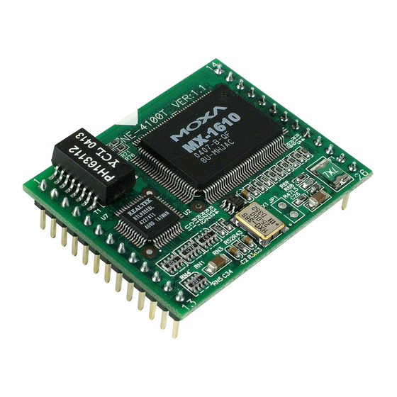
NE-4100 Series User’s Manual Panel Layout and Pin Assignments NE-4100T, NE-4100-ST The NE-4100T is a TTL-to-Ethernet drop-in module. It measures 45 × 36 mm, and has a dual-in-line, 26-pin design, making it easy to integrate with your serial devices. The NE-4100-ST is the evaluation board for testing NE-4100T modules and developing your own applications. -
Page 12: Pin Assignments
NE-4100 Series User’s Manual Panel Layout and Pin Assignments LED Name LED Color LED Function DIO0 Indicates that DIO is in “low” (0) status. DIO1 Indicates that DIO is in “low” (0) status. DIO2 Indicates that DIO is in “low” (0) status. -
Page 13: Block Diagrams
NE-4100 Series User’s Manual Panel Layout and Pin Assignments NE-4100-ST Serial Port Pinouts (DB9 Male) Debug Serial Port for Serial Console RS-232 Port for Connecting Serial Devices Signal Signal DIO Terminal Block Block Diagrams +5 VDC Customer’s Device 1 MB SDRAM... -
Page 14: Ne-4110S, Ne-4110A, Ne-4110-St
NE-4100 Series User’s Manual Panel Layout and Pin Assignments NE-4110S, NE-4110A, NE-4110-ST The NE-4110S is an RS-232-to-Ethernet server, and the NE-4110A is an RS-422/485-to-Ethernet server. Both models use an RJ45 connection and measure 57 × 40 mm. The NE-4110-ST is the evaluation board for testing NE-4100S and NE-4110A modules and developing your own applications. -
Page 15: Ne-4110-St Led Indicators
NE-4100 Series User’s Manual Panel Layout and Pin Assignments NE-4110-ST LED Indicators LED Name LED Color LED Function Power Indicates the power is on. Steady on: Power is on and NE-4110 is functioning normally. Green Blinking: NE-4110 has been located by Ready Network Enabler Administrator. - Page 16 NE-4100 Series User’s Manual Panel Layout and Pin Assignments ATTENTION For the 2-wire RS-485 interface, pin 3 is for Data+ (B) and pin 4 is for Data- (A). NE-4110S and NE-4110A Ethernet Port Pinouts Signal RJ45 Port NE-4110S and NE-4110A DIO and LED Header Pinouts (J2)
-
Page 17: Block Diagrams
NE-4100 Series User’s Manual Panel Layout and Pin Assignments Block Diagrams NE-4110S Block Diagram +5 VDC 1 MB SDRAM 2 MB Flash Serial data Customer’s device (Tx, Rx, RTS, CTS, DTR, DSR, DCD) 10/100 M 80186 CPU Ethernet PHY Line... -
Page 18: Ne-4120S, Ne-4120A, Ne-4120-St
NE-4100 Series User’s Manual Panel Layout and Pin Assignments NE-4120S, NE-4120A, NE-4120-ST The NE-4120S is an RS-232-to-Ethernet server, and the NE-4120A is an RS-422/485-to-Ethernet server. Both models use pin headers instead of RJ45 connectors. The NE-4120-ST is the evaluation board for testing NE-4120S and NE-4120A modules and developing your own applications. -
Page 19: Ne-4120-St Led Indicators
NE-4100 Series User’s Manual Panel Layout and Pin Assignments NE-4120-ST Jumper 7 (J7) Jumper 9 (J9) 149.00 mm Ethernet Port 9 10 Power Jack 13 14 Jumper 10 (J10) Interface D I P DI/O Selector Selector Jumpers Jumpers DI/O Signal... -
Page 20: Pin Assignments
NE-4100 Series User’s Manual Panel Layout and Pin Assignments Pin Assignments NE-4120S Serial Header Pinouts (J1) RTS0 CTS0 DSR0 TxD0 DTR0 RxD0 DCD0 NE-4120A Serial Header Pinouts (J1) RxD- RxD+ TxD+ TxD- ATTENTION The symbols “B” and “A” are often used in place of “+” and “-”, respectively. -
Page 21: Block Diagrams
NE-4100 Series User’s Manual Panel Layout and Pin Assignments NE-4120-ST Pinouts Debug Serial Port for Serial Console RS-232 Port for Serial Devices Signal Signal Serial and DIO Terminal Blocks TXD+ TXD- RXD+ RXD- SGND Data+ Data- Block Diagrams NE-4120S Block Diagram... - Page 22 NE-4100 Series User’s Manual Panel Layout and Pin Assignments NE-4120A Block Diagram +5 VDC 1 MB SDRAM 2 MB Flash RS-422/485 Customer’s device Signal 10/100 M 80186 CPU Ethernet PHY RS-422/485 Line UART0 interface Driver Transformer GPIO Port UART1 1.5 KV isolation...
-
Page 23: Chapter 3 Getting Started
Getting Started Chapter 3 This chapter includes information about installation of NE-4100 Series modules for development and testing. The following topics are covered in this chapter: Wiring Precautions Installing the NE-4100T onto the NE-4100-ST Installing the NE-4110S, NE-4110A onto the NE-4110-ST... -
Page 24: Wiring Precautions
NE-4100 Series User’s Manual Getting Started Wiring Precautions This section describes some important safety precautions that you should pay attention to before proceeding with any installation. ATTENTION Be sure to disconnect the power cord before installing or wiring the evaluation board. -
Page 25: Installing The Ne-4100T Onto The Ne-4100-St
NE-4100 Series User’s Manual Getting Started Installing the NE-4100T onto the NE-4100-ST Before using the NE-4100-ST evaluation board with the module, disconnect the power supply, network, and serial device. In the center of the evaluation board, there is a square with one white inverted triangle (shown as black in the figure) on one of its sides, and 2 rows of female sockets on the other two sides. -
Page 26: Installing The Ne-4120S, Ne-4120A Onto The Ne-4120-St
D I P Selecting the Serial Interface NE-4100 Series modules are available for different serial interfaces. The NE-4110S and NE-4120S are designed for the RS-232 interface, and the NE-4110A and NE-4120A are designed for the RS-422/485 interface. On the NE-4110-ST and NE-4120-ST evaluation boards, the Network Enabler Interface jumper block is used to select the serial interface used for your particular module. -
Page 27: Circuit Pad For External Connection
NE-4100 Series User’s Manual Getting Started Circuit Pad for External Connection A circuit pad is provided on the right side of each evaluation board for the development of additional application circuits. 3.3V 9 10 9 10 13 14 13 14 D I P The first row of the circuit pad is for connecting a 5V power supply;... -
Page 28: Connecting To The Network
NE-4100 Series User’s Manual Getting Started Connecting to the Network To connect to the network for testing and development purposes, the module should be installed onto its evaluation board. Make sure that the module is correctly installed onto the evaluation board, then plug the Ethernet cable into the RJ45 jack. - Page 29 NE-4100 Series User’s Manual Getting Started DI/O Selectable Jumper DI/O Mode DI DO Digital Input 0 1 2 3 ON: Low D I P OFF: High Digital Input Signal Setting Switch Digital Output : Low DO0 DO1 DO2 DO3 Digital Output LEDs...
-
Page 30: Digital Output Led Circuit Design
NE-4100 Series User’s Manual Getting Started Digital Output LED Circuit Design The figure shown below is the digital output LED circuit design. This is known as the “sink” design. Dout 3.3V When developing your own applications, you need to be aware of the voltage limits shown below. -
Page 31: Choosing The Proper Operation Mode
Choosing the Proper Operation Mode Chapter 4 In this section, we describe the various operation modes of NE-4100 Series modules. Depending on your intended use, the operation mode will determine how serial communication is handled by the network. There is an operation mode for COM port mapping from the host computer as well operation modes for TCP/IP protocols. -
Page 32: Overview
Choosing the Proper Operation Mode Overview NE-4100 Series modules act as a bridge to connect your serial devices to the Ethernet. The built-in TCP/IP stack means less time spent on programming networking protocols. With one step you may choose the proper operation mode, then use your computer to access, manage, and configure your serial device from anywhere in the world over the Internet. -
Page 33: Tcp Client Mode
NE-4100 Series User’s Manual Choosing the Proper Operation Mode TCP Client Mode TCP Client Mode In TCP Client mode, the module can actively establish a TCP connection to a pre-defined host computer when serial data arrives. After the data has been transferred, the module can automatically disconnect from the host computer by using the “TCP alive check time”... -
Page 34: Real Com Mode
NE-4100 Series User’s Manual Choosing the Proper Operation Mode Real COM Mode Real COM Mode Real COM mode allows users to continue using software that was written for pure serial communications applications. Each module comes equipped with COM drivers for Windows systems (95 and above). -
Page 35: Initial Ip Address Configuration
Initial IP Address Configuration Chapter 5 When setting up your NE-4100 Series module for the first time, the first thing you should do is configure the IP address. This chapter introduces the methods that can be used to configure the module’s IP address. -
Page 36: Static Vs. Dynamic Ip Address
IP address, which can be leased from a local ISP. NE-4100 Series Administration Suite The NE-4100 Series Administration Suite consists of some useful utilities that are used to configure and manage the module. Please refer to Chapter 7 for details on using the NE-4100 Series Administration Suite to set up the module’s IP addresses. -
Page 37: Telnet Console
NE-4100 Series User’s Manual Initial IP Address Configuration To configure the IP address using ARP, follow these instructions: 1. Obtain a valid IP address for the module from your network administrator. 2. Obtain the module’s MAC address from the label on the module. - Page 38 NE-4100 Series User’s Manual Initial IP Address Configuration 3. Select Network settings by pressing 2 and then Enter. << Main Menu >> (1) Basic setting (2) Network settings (3) Serial settings (4) DIO setting (5) Operating settings (6) Accessible IP settings...
- Page 39 NE-4100 Series User’s Manual Initial IP Address Configuration 6. Press any key to continue. << Main Menu->Network settings >> (1) IP address (2) Netmask (3) Gateway (4) IP configuration (5) DNS server 1 (6) DNS server 2 (7) SNMP (8) SNMP community name...
-
Page 40: Serial Console (19200, N, 8, 1)
NE-4100 Series User’s Manual Initial IP Address Configuration 9. Press Y and then Enter to save the new IP address and restart the module. Ready to restart (y) Yes (n) No Key in your selection: y_ Serial Console (19200, n, 8, 1) - Page 41 NE-4100 Series User’s Manual Initial IP Address Configuration 7. The serial console will open up. At this point, it will look exactly the same as the Telnet console. Please continue to step 3 in the previous Telnet Console section for the rest of the instructions on setting up the IP address.
-
Page 42: Web Console Configuration
Web Console Configuration Chapter 6 The web console is the most user-friendly way to configure your NE-4100 Series module. This chapter introduces the web console function groups and function definitions. This chapter includes the following sections: Opening Your Browser Web Console Navigation... -
Page 43: Opening Your Browser
If you use other web browsers, remember to enable the functions to “allow cookies that are stored on your computer” or “allow per-session cookies.” NE-4100 Series modules only use cookies for password transmission. ATTENTION Please refer to Chapter 5, Initial IP Address Configuration for instructions on IP configuration. -
Page 44: Web Console Navigation
NE-4100 Series User’s Manual Web Console Configuration ATTENTION If you forget the password, the ONLY way to configure the module is to “load factory defaults.” Remember to use Network Enabler Administrator to export the configuration file when you have finished the configuration. After loading factory defaults, your configuration can be easily reloaded into the module. - Page 45 Optional time.nist.gov) NE-4100 Series modules use SNTP (RFC-1769) for auto time calibration. Enter the Time Server IP address or domain address. When the Time Server IP address is provided, the module will request time information from the Time Server every 10 minutes.
-
Page 46: Network Settings
NE-4100 Series User’s Manual Web Console Configuration Network Settings NOTE: “Serial Command Mode” is supported in firmware version 3.0 and above. You must assign a valid IP address to the module before it will work in your network environment. Your network system administrator should provide you with an IP address and related settings for your network. - Page 47 NE-4100 Series User’s Manual Web Console Configuration IP Address Setting Factory Default Necessity E.g., 192.168.1.1 (IP addresses of the form x.x.x.0 and 192.168.127.254 Required x.x.x.255 are invalid.) An IP address is a number assigned to a network device, such as a computer, as a permanent address on the network.
- Page 48 NE-4100 Series User’s Manual Web Console Configuration SNMP Settings Community name Setting Factory Default Necessity 1 to 39 characters public Optional (E.g., Support, 886-89191230 #300) A community name is a plain-text password mechanism that is used to weakly authenticate queries to agents of managed network devices.
-
Page 49: Serial Settings
NE-4100 Series User’s Manual Web Console Configuration Auto report period Setting Factory Default Necessity Time interval (in seconds) Optional The Auto report period field specifies how often the module will report its IP address. An auto report period of 10 seconds means that an IP address report will be sent every 10 seconds. -
Page 50: Operating Settings
NE-4100 Series User’s Manual Web Console Configuration Data Bits Setting Factory Default Necessity 5, 6, 7, 8 Required When the user sets Data Bits to 5 bits, the Stop Bits setting will automatically change to 1.5 bits. Stop Bits Setting... - Page 51 NE-4100 Series User’s Manual Web Console Configuration TCP alive check time Setting Factory Default Necessity 0 to 99 min 7 min Optional 0 min: The TCP connection is not closed due to an idle TCP connection. 1 to 99 min: The module automatically closes the TCP connection if there is no TCP activity for the given time.
- Page 52 NE-4100 Series User’s Manual Web Console Configuration Delimiter 2 Setting Factory Default Necessity 00 to FF “0” for None Optional The Delimiter fields are used to specify a character or 2-character sequence which will act as a marker to control packing of serial data. By default, no delimiter characters are defined, so the module transmits data as soon as it is received.
-
Page 53: Real Com Mode
NE-4100 Series User’s Manual Web Console Configuration Since it requires about 9 ms to send one character, the Force transmit should be 10 ms or more to have any effect. At 9 ms or less, the module will simply pack every character as it is received, which would be the same as if no delimiter characters or Force transmit time were specified at all. - Page 54 NE-4100 Series User’s Manual Web Console Configuration Application software that is based on the COM driver will receive a driver response of “success” when the software uses any of the Win32 API functions. The firmware will only send the data back to the driver on the host.
-
Page 55: Tcp Client Mode
NE-4100 Series User’s Manual Web Console Configuration Force transmit Setting Factory Default Necessity 0 to 65535 ms 0 ms Optional 0: The force transmit timeout is disabled. 1 to 65535: If the module does not receive the next byte of data within the time specified, it will packed the data in its buffer into the same data frame for network transmission. - Page 56 NE-4100 Series User’s Manual Web Console Configuration TCP alive check time Setting Factory Default Necessity 0 to 99 min 7 min Optional 0 min: The TCP connection is not closed due to an idle TCP connection. 1 to 99 min: The module automatically closes the TCP connection if there is no TCP activity for the given time.
- Page 57 NE-4100 Series User’s Manual Web Console Configuration Use Delimiter 1 to define the first delimiter character in hex. If only one delimiter character will be used, Delimiter 2 should be set to “0”. If the delimiter will be a two-character sequence, use Delimiter 2 to define the second character.
-
Page 58: Udp Mode
NE-4100 Series User’s Manual Web Console Configuration ATTENTION Up to 4 connections can be established between the module and hosts. The connection speed or throughput may be low if one of the four connections is slow. In this case, the other 3 connections will be delayed while waiting for the slowest connection to finish transmitting or receiving. - Page 59 NE-4100 Series User’s Manual Web Console Configuration The Delimiter fields are used to specify a character or 2-character sequence which will act as a marker to control packing of serial data. By default, no delimiter characters are defined, so the module transmits data as soon as it is received.
-
Page 60: Accessible Ip Settings
NE-4100 Series User’s Manual Web Console Configuration Destination IP address 1/2/3/4 Setting Factory Default Necessity IP address range E.g., Begin: 192.168.1.1 End: None Required 192.168.1.10 Local Listen port Setting Factory Default Necessity 1 to 65535 4001 Required Use this field to specify the UDP port that the module listens to and that other devices must use to contact the module. -
Page 61: Auto Warning Settings
Optional ATTENTION Consult your network administrator or ISP for the proper mail server settings. The Auto warning function may not work properly if not set up properly. NE-4100 Series SMTP AUTH supports LOGIN, PLAIN, CRAM-MD5 (RFC 2554). 6-20 RSPSupply - 1-888-532-2706 - www.RSPSupply.com... -
Page 62: Event Type
NE-4100 Series User’s Manual Web Console Configuration SNMP trap server SNMP trap server IP or domain name Setting Factory Default Necessity IP or Domain Name None Optional Event Type NOTE: “Serial Command Mode” is supported in firmware version 3.0 and above. -
Page 63: Digital Io
NE-4100 Series User’s Manual Web Console Configuration DCD changed, DSR changed DCD (Data Carrier Detect) and DSR (Data Set Ready) signals indicate serial communication status. Administrators can receive e-mail and SNMP trap warnings when there is a status change to the serial port. -
Page 64: Dio Monitor
NE-4100 Series User’s Manual Web Console Configuration DIO Monitor The DIO Monitor page polls and displays the mode and status of each DIO channel. You may use this page to verify changes that were made in the DIO Settings page. -
Page 65: Load Factory Defaults
NE-4100 Series User’s Manual Web Console Configuration Load Factory Defaults To load the factory default settings, click on Load Factory Default in the navigation panel and then click on Submit. All previous modifications will be lost. NOTE: “Serial Command Mode” is supported in firmware version 3.0 and above. -
Page 66: Network Enabler Administrator
Network Enabler Administrator Chapter 7 Network Enabler Administrator is a Windows utility that can be used to configure NE-4100 Series modules. In this chapter, we will discuss how to install and use Network Enabler Administrator. This chapter includes the following sections:... -
Page 67: Overview
NE-4100 Series User’s Manual Network Enabler Administrator Overview NE-4100 Series modules are shipped with an integrated software suite that bundles Network Enabler Administrator and the IP Serial Library. The suite provides everything you need to remotely manage, monitor, and modify the module—hassle free. - Page 68 NE-4100 Series User’s Manual Network Enabler Administrator 4. Click Install to install program files in the default directory. 5. The Installing window will report the progress of the installation. 6. Click Finish to complete the installation of Network Enabler Administrator.
-
Page 69: Network Enabler Administrator Navigation
NE-4100 Series User’s Manual Network Enabler Administrator Network Enabler Administrator Navigation The Network Enabler Administrator-Configuration window is divided into four parts. The top section is the menu and help area. Please note that the help file is not compatible with Windows NT The left panel is the navigation panel and lists the available types of functions. -
Page 70: Configuration Functions
Specify by IP Address to find the module in order to unlock other functions. Broadcast Search Broadcast Search is used to find all NE-4100 Series modules that are connected to the same LAN as your computer. Since the Broadcast Search function searches by MAC address and not IP address, all NE-4100 Series modules connected to the LAN will be located, regardless of whether or not they are part of the same subnet as the host. -
Page 71: Specify By Ip Address
NE-4100 Series User’s Manual Network Enabler Administrator 2. A Searching window will open, showing that the program is searching for NE-4100 Series modules connected to this network. You may click Stop as soon as the desired module is found. 3. After the search is finished, all modules that were found will be shown in the Configuration module list. -
Page 72: Unlock
NE-4100 Series User’s Manual Network Enabler Administrator Unlock Unlock is used to enter the password of locked modules in order to view and changes settings. In the Configuration module list, the Status field shows the password status of the module, as... -
Page 73: Configure
NE-4100 Series User’s Manual Network Enabler Administrator 2. After entering the correct password, the following window will open. After a module has been unlocked, it remains unlocked for the duration of the Network Enabler Administrator session, even if a new password is assigned. - Page 74 NE-4100 Series User’s Manual Network Enabler Administrator 3. After the processing is done, the following window will open. NOTE: “Serial Command Mode” is supported in firmware version 3.0 and above. The module’s parameters are divided into ten tabs—Basic, Network, Serial, Operating Mode, Accessible IPs, Auto Warning, IP Address Report, Password, Digital IO, and Serial CMD.
-
Page 75: Upgrade Firmware
NE-4100 Series User’s Manual Network Enabler Administrator Upgrade Firmware Upgrade Firmware is used to upload new firmware to the selected module. 1. Select Upgrade Firmware from the Configuration context menu. Note that this menu may also be opened by right-clicking Configuration in the navigation panel, or by right-clicking the selected module. -
Page 76: Import And Export Configuration
NE-4100 Series User’s Manual Network Enabler Administrator Import and Export Configuration The module’s configuration can be imported from a configuration text file by right-clicking the module and selecting Import Configuration in the Configuration context menu. Note that this menu may also be opened by right-clicking Configuration in the navigation panel, or by right-clicking the selected module. -
Page 77: Monitor Functions
NE-4100 Series User’s Manual Network Enabler Administrator Monitor Functions Monitor functions allow the monitoring of the selected module’s connection and other basic settings over the network. Modules are added to the module list using Add Target or Load Configured COM Port. -
Page 78: Load Configured Com Port
NE-4100 Series User’s Manual Network Enabler Administrator 3. Once the target has been selected, it will show up on the list in the Monitor module list. Note that monitoring does not actually begin until Go is selected from the context menu. - Page 79 NE-4100 Series User’s Manual Network Enabler Administrator Monitor Items In the Monitor Items tab, you may select which items of information will be monitored. General Settings In the General Settings tab, you may select how often the module is monitored, which is known as the refresh rate.
-
Page 80: Go And Stop
NE-4100 Series User’s Manual Network Enabler Administrator Advanced Settings In the Advanced Settings tab, you may enable an alarm to warn you of monitor events. You may choose an audible alarm as well as a pop-up warning message. Go and Stop Go and Stop are used to activate and deactivate monitoring of the modules in the module list. -
Page 81: Port Monitor Functions
NE-4100 Series User’s Manual Network Enabler Administrator If a monitored module loses its connection with Network Enabler Administrator, a warning message will appear and an audible alarm will sound, as configured in the Monitor settings. If the module’s connection is restored, another message will be displayed, as configured in the Monitor settings. -
Page 82: Com Mapping Functions
NE-4100 Series User’s Manual Network Enabler Administrator In addition, individual COM ports in the module list may be selected or deselected for monitoring. COM Mapping Functions Network Enabler Administrator is installed with Real COM drivers that work with Windows 95 and above. - Page 83 NE-4100 Series User’s Manual Network Enabler Administrator Basic Settings In the Basic Settings tab, you may map a local COM port number to the selected module. Make sure that Auto Enumerating COM Number for Selected Ports is checked when using mapping to multiple modules.
-
Page 84: Enable And Disable
NE-4100 Series User’s Manual Network Enabler Administrator When Tx Mode is set to Hi-Performance, the Real COM driver sends a “Tx Empty” signal to the host as soon as it sends serial data over the network to the selected module. In Hi-performance mode, the driver will not verify that the module has successfully received and passed the data to the serial device. -
Page 85: Apply And Discard Change
NE-4100 Series User’s Manual Network Enabler Administrator Apply and Discard Change Apply Change and Discard Change are used to save or delete any changes COM mapping settings. Select Apply Change in the COM Mapping context menu to save any changes made to the COM mappings;... -
Page 86: Linux And Unix Configuration
Linux and UNIX Configuration Chapter 8 NE-4100 Series modules can be configured to work with Linux and UNIX operating systems. Drivers are included on the CD that comes with the module. This chapter includes the following sections: Linux Real TTY Drivers... -
Page 87: Linux Real Tty Drivers
NE-4100 Series User’s Manual Linux and UNIX Configuration Linux Real TTY Drivers Basic Procedures The basic procedures to map a Linux host’s tty port to the module’s serial port are as follows: 1. Set up the module. After verifying that the IP configuration works and you can access the module (by using ping, telnet, etc.), configure the module’s serial port to Real COM mode. -
Page 88: Mapping Tty Ports
NE-4100 Series User’s Manual Linux and UNIX Configuration Mapping TTY Ports Make sure that you set the operation mode of the module’s serial port to Real COM mode. After logging in as a super user, enter the directory /usr/lib/npreal2/driver and then execute mxaddsvr to map the module’s serial port to the host tty ports. -
Page 89: Removing Linux Driver Files
NE-4100 Series User’s Manual Linux and UNIX Configuration Removing Linux Driver Files A utility is included that will remove all driver files, mapped tty ports, and unload the driver. To do this, you only need to enter the directory /usr/lib/npreal2/driver, and then execute mxuninst to uninstall the driver. -
Page 90: Configuring The Unix Driver
NE-4100 Series User’s Manual Linux and UNIX Configuration Configuring the UNIX Driver Modify the configuration The configuration used by the moxattyd program is defined in the text file moxattyd.cf, which is in the same directory that contains the program moxattyd. You may use vi, or any text editor to modify the file, as follows: ttyp1 192.168.1.1 950... -
Page 91: Serial Command Mode
Serial Command Mode Chapter 9 Serial command mode allows configuration of the module through serial commands received directly through the serial port. It is available on NE-4100 Series modules with firmware version 3.0 and above This chapter includes the following sections:... -
Page 92: Overview
NE-4100 Series User’s Manual Serial Command Mode Overview Serial command mode allows the module’s parameters to be retrieved or configured through the serial port, rather than through the console port or over the network. This is done through the use of specially parsed commands sent to the module through the serial port. -
Page 93: Reply Structure
NE-4100 Series User’s Manual Serial Command Mode Reply Structure Descriptor Bytes Character Description R-Head “<” fixed value (0x3C) Y: command was executed successfully 1: command not supported “Y”, 2: OP code not supported Reply Code “1” to “5”, 3: invalid command encapsulation “E”... - Page 94 NE-4100 Series User’s Manual Serial Command Mode Accessible IF OP Code Parameter Comments 0: disable accessible IP list filtering 1: enable xxx.xxx.xxx.xxx accessible IP address 01 (e.g., 192.168.127.1) xxx.xxx.xxx.xxx accessible IP address 02 (e.g., 192.168.127.1) xxx.xxx.xxx.xxx accessible IP address 03 (e.g., 192.168.127.1)
- Page 95 NE-4100 Series User’s Manual Serial Command Mode OP Code Parameter Comments xxx.xxx.xxx.xxx accessible IP netmask 06 (e.g., 255.255.255.0) xxx.xxx.xxx.xxx accessible IP netmask 07 (e.g., 255.255.255.0) xxx.xxx.xxx.xxx accessible IP netmask 08 (e.g., 255.255.255.0) xxx.xxx.xxx.xxx accessible IP netmask 09 (e.g., 255.255.255.0) xxx.xxx.xxx.xxx accessible IP netmask 10 (e.g., 255.255.255.0)
- Page 96 NE-4100 Series User’s Manual Serial Command Mode Real COM Mode OP Code Parameter Comments 1 – 4 max. number of connections 0 – 99 (minutes) TCP alive check time 0: no delimiter 1: enable 1-character delimiter number of characters to use as delimiter...
- Page 97 NE-4100 Series User’s Manual Serial Command Mode OP Code Parameter Comments xxx.xxx.xxx.xxx destination IP address 2, begin range (e.g., 192.168.1.1) xxx.xxx.xxx.xxx destination IP address 3, begin range (e.g., 192.168.1.1) xxx.xxx.xxx.xxx destination IP address 4, begin range (e.g., 192.168.1.1) xxx.xxx.xxx.xxx destination IP address 1, end range (e.g., 192.168.1.1)
-
Page 98: Operation Flow Chart
NE-4100 Series User’s Manual Serial Command Mode Serial Command Mode OP Code Parameter Comments 0: disable 1: enable HW trigger enable serial command mode 2: enable SW trigger three ASCII characters in hex code (i.e., “A1A2A3” for ASCII SW trigger characters... -
Page 99: Configuring Trigger Type
NE-4100 Series User’s Manual Serial Command Mode Configuring Trigger Type Serial command mode may be triggered by either software or hardware. Initially, you may use one of the following configuration tools to set the trigger type: Network Enabler Administrator, Telnet console, web console, or serial console. - Page 100 NE-4100 Series User’s Manual Serial Command Mode Select Activated by Character to trigger serial command mode through the serial port. In this case, you will also need to enter the three characters (in HEX code) that will be used as the trigger characters.
-
Page 101: Telnet Console
NE-4100 Series User’s Manual Serial Command Mode Telnet Console Please refer to Chapter 5 for information on opening the Telnet console. Press 5 and the Enter key to select Serial Command Mode setting. From the Serial Command Mode setting menu, select 1 in order to select and enable the trigger type (hardware or software). -
Page 102: Web Console
NE-4100 Series User’s Manual Serial Command Mode Web Console Please refer to Chapter 6 for information on opening the web console. Click on the Serial Command Mode folder in the navigation panel. Modify the settings as needed, and then click on Submit. Remember that you will need to save the configuration and restart the module for any changes to effect. -
Page 103: Entering Serial Command Mode
NE-4100 Series User’s Manual Serial Command Mode Entering Serial Command Mode Trigger Type The module can enter serial command mode through either a hardware trigger or a software trigger, depending on how it has been configured. Please refer to the previous section for details on how to configure the trigger type. -
Page 104: Comments
NE-4100 Series User’s Manual Serial Command Mode ATTENTION Note that using a software trigger to enable Serial Command Mode may fail if the baudrate you are using is too small. For example, using a baudrate of 110 could cause the trigger to fail. -
Page 105: Serial Command Examples
NE-4100 Series User’s Manual Serial Command Mode In the example above, the status is Data Mode, which indicates normal data transmission. For serial command mode, the status would be Command Mode. You may also verify if the module is in serial command mode by attaching a serial console to the serial port (P0). -
Page 106: Example 1: Get Model Name Using Hw Trigger
NE-4100 Series User’s Manual Serial Command Mode Example 1: Get Model Name Using HW Trigger STEP 1. Verify that the hardware trigger is enabled for serial command mode. STEP 2. Check the module’s serial port settings. STEP 3. Start Windows HyperTerminal and make sure that the PC’s serial port settings match the module’s settings. -
Page 107: Example 4: Change Tcp Port Number Using Sw Trigger
NE-4100 Series User’s Manual Serial Command Mode STEP 6. Type “>RNC” in HyperTerminal and press Enter, which requests the module’s IP mode. STEP 7. HyperTerminal displays “<YNC1”, indicating that the module’s IP mode is DHCP. STEP 8. Type “>WBR1” in HyperTerminal and press Enter, which exits serial command mode. - Page 108 These port numbers should be avoided when assigning a port number to your NE-4100 Series module; otherwise you may experience network problems. Refer to the RFC 1700 standard for Well Known Port Numbers or refer to the following introduction from IANA.
-
Page 109: Appendix A Well Known Port Numbers
NE-4100 Series User’s Manual Well Known Port Numbers TCP Socket Application Service World Wide Web HTTP Network News Transfer Protocol (NNTP) Network Time Protocol 160 – 223 Reserved for future use UDP Socket Application Service reserved Management Utility Echo Discard... - Page 110 NECI (Network Enabler Configuration Interface) is a set of APIs that run on Windows systems (95 and above) to search, locate, and configure NE-4100 Series modules over the network. The NE-4100 Series library can be found in the folder .\NECI_ LIB\ on the Documentation and Software CD included with each module.
-
Page 111: Appendix C Auto Ip Report Protocol
Auto IP Report Protocol Appendix C There are several ways to configure the IP address of an NE-4100 Series module. One of them is DHCP Client. When you set up the module to use DHCP Client for IP address configuration, it will automatically send a DHCP request over the network to find the DHCP server. -
Page 112: Ip Address Report Structure
NE-4100 Series User’s Manual Auto IP Report Protocol IP Address Report Structure The first 4 bytes of the module’s IP address report are the characters “Moxa”. The rest of the report is composed of 9 items, with each item preceded by a 2-byte header indicating the item ID and item length. -
Page 113: Overview
DIO Commands Appendix D In this appendix, we provide information on sending commands to the module’s DIO channels over an Ethernet network. Digital I/O commands and responses are accessed using a specific TCP port (default 5001) on the module. Each command is initiated by the host and is followed by a response from the module. -
Page 114: C Code Example
NE-4100 Series User’s Manual DIO Commands C Code Example //define DIO Header format typedef struct _DIO_Header_Struct { char command; char version; /* This specification is version 2 */ char status; char length; } DIOHeaderStruct, *pDIOHeaderStruct; //define DIO Packet format //Used for Command and ACK packet typedef struct _DIO_Packet_Struct { DIOHeaderStruct header;... -
Page 115: C Code Example
NE-4100 Series User’s Manual DIO Commands C Code Example BOOL ReadSingleDIO(int port, int *mode, int *status) DIOPacketStruct packet; packet.header.command = 1; // read single DIO command packet.header.version = 2; // DIO protocol version packet.header.length = 1; // data length packet.data[0] = (char)port;... -
Page 116: Command
NE-4100 Series User’s Manual DIO Commands C Code Example: void WriteSingleDIO(int port, int mode, int status) DIOPacketStruct packet; packet.header.command = 2; // write single DIO command packet.header.version = 2; // DIO protocol version packet.header.length = 3; // data length packet.data[0] = (char)port;... -
Page 117: Write Multiple Dio
NE-4100 Series User’s Manual DIO Commands Byte # Descriptor Value Description 2nd requested DIO channel Data 0, 1 0: channel status is low 1: channel status is high 3rd requested DIO channel, optional Data 0, 1 0: channel is in input mode... -
Page 118: Response
NE-4100 Series User’s Manual DIO Commands Byte # Descriptor Value Description 1st DIO channel to be written Data 0: set to input mode 1: set to output mode 1st DIO channel to be written Data 0: set to low 1: set to high... -
Page 119: C Code Example
NE-4100 Series User’s Manual DIO Commands Byte # Descriptor Value Description 2nd requested DIO channel Data 0, 1 0: channel has been changed to input mode 1: channel has been changed to output mode 2nd requested DIO channel Data 0, 1... - Page 120 Appendix E Like Group NE-4100 Series modules have built-in SNMP (Simple Network Management Protocol) agent software. It supports SNMP Trap, RFC1317 RS-232 like group and RFC 1213 MIB-II. The following table lists the standard MIB-II groups, as well as the variable implementations for NE-4100 Series modules.
-
Page 121: Snmp Agent With Mib Ii & Rs-232 Like Group
NE-4100 Series User’s Manual SNMP Agent with MIB II & RS-232 Like Group System MIB Interfaces MIB IP MIB ICMP MIB IpNetToMediaIfIndex IcmpOutAddrMaskReps IpNetToMediaPhysAddress IpNetToMediaNetAddress IpNetToMediaType IpRoutingDiscards UDP MIB TCP MIB SNMP MIB UdpInDatagrams tcpRtoAlgorithm snmpInPkts UdpNoPorts tcpRtoMin snmpOutPkts UdpInErrors...
Need help?
Do you have a question about the NE-4100 Series and is the answer not in the manual?
Questions and answers